ABSTRACT
Deformations of soft missile impacting on wall and failure mechanism of concrete wall are studied in medium scale impact tests under way at the Technical Research Centre of Finland (VTT). In the tests, deformable projectiles are impacted a solid concrete wall or a steel force-measurement plate.
The test apparatus accelerates missiles horizontally against a vertical wall. The missiles are accelerated on rails above a tube acting as an air gun barrel; they are driven by a piston which in turn is driven by compressed air. The air is stored in a pressure accumulator with a rupture disk between the accumulator and the shooting tube. The disk is designed to rupture at a desired accumulator pressure, allowing control of the impact velocity. The weight and fundamental frequency of the frame supporting the wall have been designed to yield very small displacements during the short time interval of the actual impact.
The main objective of this apparatus is to provide data for the calibration and verification of numerical models of a loading scenario where a soft deformable missile crushes against a reinforced concrete wall. The facility has been designed to allow maximal geometric freedom for missile design. Special care has been taken to allow lateral extension needed for winged missiles, representing aircraft.
In some tests, the missile has contained a lot of liquid or soft solid material. The experiments have provided information on the impact force-time function for soft missile impacts against a rigid wall, on the fracturing process of a concrete wall due to impact, and on the spreading of liquid droplets.
All the missiles shot so far were cylinder pipes made of steel or aluminium. Many have had axially varying mass and strength distribution. Missile masses have ranged from 20 to 110 kg and the final velocity of the missile has ranged from 70 m/s to 190 m/s.
The main parameters measured were: the velocity of the missile, the force-time function during the impact, displacements and strains in the reinforcement of the concrete wall and extent of liquid spreading. An extremely fast and accurate multi-channel data acquisition system has been built especially for this facility. High-speed photography is used to obtain qualitative information of missile breakup and wall response.
About fifty tests have been carried out so far. The test facility and data acquisition system work well and are suitable for accelerating a broad range of soft missiles. Experiment reproducibility is very good.
Experiments using more complex, airplane-like missiles are being planned as the next step; as well as testing with various concrete wall parameters, including various stirrup design, wall prestressing, etc.
INTRODUCTION
The purpose of the impact tests and facility is to accelerate deformable missiles towards a force plate or a reinforced concrete wall. Results from such tests are needed to validate numerical models that are used to assess the structural safety of nuclear power plant buildings [1].
After the events of the 11thof September, the Finnish Radiation and Nuclear Safety Authority (STUK) required future nuclear reactors to be designed to withstand an intentional crash of a large passenger aircraft. This requirement was immediately implemented in the design of Olkiluoto 3, currently under construction. In order to support the assessment of the Finnish NPP’s, the Technical Research Centre of Finland (VTT) designed a new facility where impact tests with a medium scale model of an aircraft could be carried out. The missile driver design was added to an existing large shock tube facility, used by VTT during four decades. [2]
In the beginning the research was financed by the Finnish national nuclear safety research program SAFIR, but later international research institutes and partners have also joined the project.
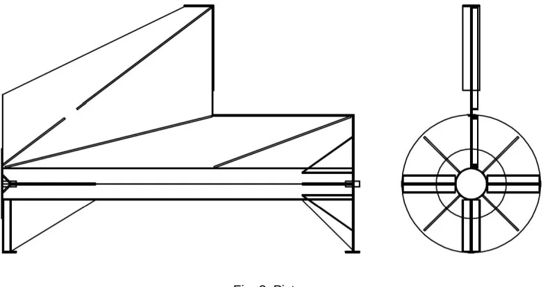
Fig. 1. Facility
Pressure accumulator and rupture disk
The pressure accumulator pipe is 13.5 m long steel tube and it is acting as a driver section. The volume of the pressure accumulator is 2.65 m3and it is designed for 6000 kPa overpressure. There is a duct at the back of the accumulator to feed the driver gas (air) to the accumulator.
The end of the pressure accumulator is closed using a disk which ruptures when the overpressure in the accumulator reaches a desired level. The pressure at burst is controlled by the material, thickness and number of disks. Depending on the desired pressure level metal and plastic sheets are used as rupture disk. After the disk ruptures, a shock wave propagates into the acceleration tube, driving the piston which pushes the missile forward.
In more recent tests a new system of twin disks with intermediate support pressure in between them is used, to allow an even more accurate control of driving pressure. Rupture pressure has varied between 300 and 1900 kPa.
Acceleration tube
The acceleration tube is made of steel and its length is 12.0 m. In the upper part of the tube there is a slot. Correspondingly, on the piston there is a fin which extends out of the slot. The fin transmits the force to the missile, which travels on the rails above the acceleration tube. One piston type that has been used is shown in Fig. 2.
Large part of the energy stored in the pressure accumulator is lost because of the slot in the acceleration tube and the clearance between the piston plate and the acceleration tube. About a quarter of the produced energy is used to move the missile and the piston [3].
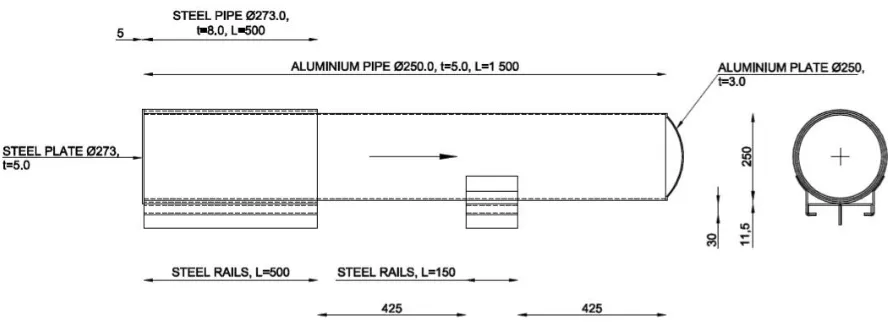
missile type that has been used is shown in Fig. 3 and 4.
Fig. 3. Missile on the rails waiting for the launch in test 642
Fig. 4. Drawing of the missile used in test 642
Target
Fig. 5. Force plate construction
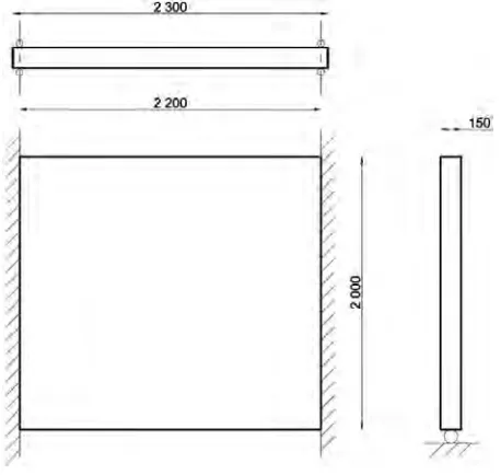
The concrete wall is supported by a steel frame. The frame is supported to the back wall of the test hall using the same steel pipes that support the force plate construction. The vertical edges of the concrete wall are simply supported and the horizontal edges are free as shown in Fig. 6, together with the dimensions of the tested walls (150×2000×2300 mm). This support scheme was developed to allow the wall to bend despite its relatively large thickness. The compression strength of concrete was approximately 60 MPa when the walls were tested.
Fig. 6. Wall support
MEASUREMENTS
back of the wall.
The strains in the reinforcement bars are measured by strain gauges fixed on the rebars inside the wall. During some tests, strain gauge measurements in the middle of the wall failed due to the breaking of the wires. So far, gauges with capacity of only 5% strain have been used, but the capacity will be raised for the forthcoming tests. In addition, the gauges measure the strain only locally in a very small area.
The dynamic behavior of the wall can be measured by shock accelerometers, which are installed on the back surface of the concrete wall. Theoretically, it is possible to calculate the deflection modes of the wall from the acceleration results by integration, but in practice, the results are not very useable due to the great extent of noise they have. In addition, the shock accelerometers are unable to measure accelerations of low frequencies describing the first deflection mode of the wall.
The acceleration of the missile is measured using an accelerometer installed at the back of the missile. The measurements have been successful with slow missile velocities (<120 m/s) throughout the tests, but with a high velocity the potential breaking of the wire terminates the measurement and prevents the whole data from the test to be recorded. A wireless measuring system has been considered, but not used due to its insufficient data acquisition speed.
The impact tests are shot using high speed video cameras. The images are shot with the speed of 1000 frames per second and using 35 spotlights (500 W power) in front and at the back of the wall. The useable frame rate is limited by the lighting. In some tests also normal speed video cameras are used to obtain an overall picture of the test performance and in other tests the spreading of the liquid is photographed by a stroboscope. All these methods together enable the estimation of the speed and the size of the liquid droplets caused by the impact.
All the data has been filtered and saved to a computer using a data acquisition speed of 100 kS/s (100 000 samples per second). The number of channels has been 16 to 24 depending on the test. The measuring program used is LabVIEW 8.0 by National Instruments. The instrument cables had to be sheltered by steel profiles in order to prevent the missile and concrete particles from damaging the cables. The video material and measurement data are collected into a data base for analyzing and verifying.
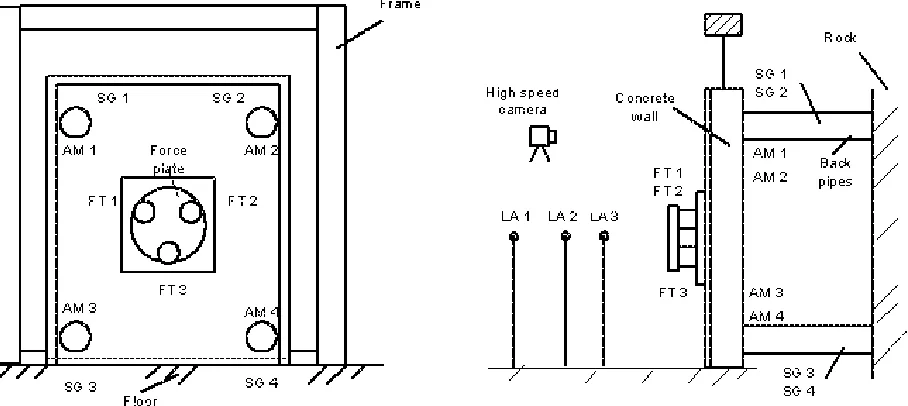
The transducers, lasers and video cameras used in the first force plate tests are shown in Fig. 7.
RESULTS
So far, approximately 50 tests including 8 concrete wall tests were conducted. Some missiles were filled with water. Impact velocities and missile masses vary from 70 m/s to 190 m/s and 20 kg to 110 kg, respectively (Fig. 8).
In the next chapters, the basics of two different tests are explained. As a rule, the detailed test data are not openly available because of security considerations; nevertheless, the project administration has decided to publish selected representative results. The locations of displacement sensors and strain gauges in rebars for these tests are shown in Fig. 9.
Fig. 8. Missile masses and impact velocities in tests in May ’06 till April ’07: 13 force plate tests (blue) and 8 wall tests (red).
(a) (b)
errors are relatively frequent. The sides on which the sensors were located were switched for almost every test. In some tests they were not installed properly and reached their maximum before 50 mm displacement as shown in Fig. 11 (a). With higher missile velocities, displacement sensors near the impact center break due to the water in missiles and/or the perforation of the wall.
Strain gauge FH1 was placed on the front side reinforcement in the horizontal bar, strain gauges BH2-BH6 on the backside reinforcement in the horizontal bar and BV7-BV8 on the backside reinforcement in the vertical bar. Also strain gauges often reached their maximum capacity. Capacity for 5 % strain is not enough in tests where the damage approaches the perforation point. In test 642 the gauges showed good results because the strains were low overall. The results are analyzed in more detail by Saarenheimo et al. [4].
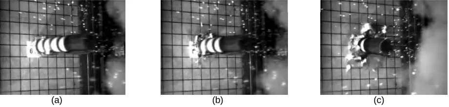
(a) (b) (c)
Fig. 10. Missile (a) 1 ms, (b) 3 ms after and (c) 11 ms after the impact in test 642.
(a) (b)
Fig. 11. (a) Displacements of the wall and (b) strains in reinforcement in test 642.
Test 644 in August ‘06
Permanent deflection in the middle of the wall was 41 mm. Strain gauges were placed as shown in Fig. 9 (b). The water spray from the impact flushed the whole sensor D4 and its frame away. Saarenheimo et al. shows more results of this test [4]. The spreading of water and droplets was also measured, as detailed by Silde et al. [5].
Fig. 12. Drawing of missile used in test 644
SUMMARY AND CONCLUSION
The IMPACT facility has been developed starting from 2003 and has reached now a mature status where well repeatable tests can be conducted and broad range of dynamic data acquired reliably. Most important measurements are the force-time function of impact (including effects of liquid possibly contained in the missile) and for walls dynamic displacement (at selected locations) and strains in wall reinforcement.
Some 50 tests have been done successfully and the test campaign is now moving towards more complex and more elaborate, aircraft-like missile designs.
REFERENCES
1. Saarenheimo, A., Hakola, I., Hyvärinen, J, and Tuomala, M., “Numerical and experimental studies on impact loaded concrete structures,” Proc. of ICONE 14, International Conference on Nuclear Engineering. ICONE14-89477, Miami, USA, July 2006.
2. Hakola, I. and Kärnä, T,Impact tests, testing facility, SAFIR The Finnish Research Programme on Nuclear Power Plant Safety, Finland, 2005.
3. Liepmann, H. W., Roshko, A.,Elements of gasdynamics, Dover Publications, inc, Mineola, New York, 2001. 4. Saarenheimo A., Tuomala M., Calonius K., Lastunen A., Myllymäki J. and Hyvärinen J., “Numerical studies of
impact loaded reinforced concrete walls,“Paper submitted for SMiRT 2007.