A PFC Based Four Switch BLDC Motor
Sofiya A1, Dr Bindu S J2 , Jasna Basheer3, Rekha T4, Gopakumar.M5, Nkhil P Naick6 , Deepak Dileep7 ,Jose Johnson8, Nishad9
Assistant Professor, Department of Electrical & Electronics Engineering, College of Engineering, Perumon, Kerala,
India1-3
B. TECH Scholars, Department of Electrical & Electronics Engineering, Collage of Engineering, Perumon, Kerala, India4-8
ABSTRACT: A BLDC Motor is well suited in large number of applications because of its high efficiency , high reliability , high torque and watt per unit weight , long life time. In conventional control method of BLDC motor a bridge rectifier with a 6 switch VSI were used. But the major problem involved in this method is that the current wave form become distorted and the supply power factor reduced .In this paper a PFC (Power Factor Corrected) bridgeless zeta converter based VSI (Voltage Source Inverter) fed BLDC motor drive. The major function of this research is to control the brushless DC motor with sensorless control of four switch three phase inverter. This system simplified the topological structure of the six switch 3 phase inverter.
KEYWORDS: BLDC brushless dc motor;PFC power factor correction
I. INTRODUCTION
requires threesensors (one current and two voltage sensors) for operation andthus increases the overall cost of drive system. This paperexplores the potential of Zeta converter for BLDC motor drivetargeting special class of applications. Moreover, possibilitiesof employing a bridgeless configuration in Zeta converter arestill unexplored. The drive system is needed to be developedwhich mustincorporate features like low cost, high efficiencyand satisfactory performance with improved power quality atthe AC mains for a wide range of speed control. This work istargeted to achieve all these objectives in the proposed drive.
II. PROPOSED BRIDGELESS ZETZ CONVERTER
Figure 1shows the proposed bridgeless Zeta converter based VSI fed BLDC motor drive. A single stage, bridgeless Zeta converter is used for the DC link voltage control and PFC operation. A front-end converter operating in DCM utilizes a voltage follower approach which requires a single voltage sensor for PFC and voltage control. This eventually, reduces the cost of the drive system on behalf of sensor reduction. Since, the speed is controlled by controlling the DC link voltage of the VSI, hence fundamental frequency switching of the VSI (through electronic commutation of BLDC motor) is used which offers low switching losses [8]. Moreover, the conduction losses of the DBR are reduced to half by using a bridgeless topology which also offers improved thermal utilization of the converter’s switches. The performance of the
proposed drive is evaluated for wide range of speed control with improved power quality at AC mains. Performance is also evaluated for wide variation in supply voltages to demonstrate the performance for practical supply systems. The power quality indices thus obtained are observed within the prescribed limits by international power quality standards such
as IEC-61000-3-2 [1].
Operation of Bridgeless Zeta Converter
A bridgeless topology is designed such that two switches conduct independently for the positive and negative half cycle of the supply voltage [5-7]. The conduction losses of the DBR are reduced to half as compared to conventional topology due to the bridgeless configuration. Moreover, this also improves the thermal utilization of switches since switch rms current is divided into two switches.
A.OPERATION DURING COMPLETE CYCLE OF SUPPLY VOLTAGE
Figure 2 (a) and (b) show the operation of bridgeless Zeta converter for a positive and negative half cycle of the supply voltage respectively. As shown in Figure 2(a), switch Sw1 and diode D1 conduct for the positive half cycle of the supply voltage and diode D2 remains reversed biased during this period. Similarly for the negative half cycle of the supply voltage, switch Sw2 and diode D2 conduct and no current flows through switch Sw1 and diode D1 as shown in Fig. Figure 2(b).Theenergy is transferred through HFT(High Frequency Transformer) which turns ratio is given as N1:N1:N2. The magnetizing inductance (Lm) is designed to operate in DCM such that a discontinuous conduction is achieved for a wide range of DC link voltage control to achieve an inherent power
factor correction.
B.OPERATION DURING COMPLETE SWITCHING CYCLE
Figure 1 Proposed bridgeless Zeta converter
Figure 2 (a-d) Different modes of operation of the proposed bridgeless Zetaconverter fed BLDC motor drive and the (e) associated waveforms
C.DESIGN OF BRIDGELESS ZETA CONVERTER FED BLDC MOTOR DRIVE
A 500W PFC bridgeless Zeta converter is designed for VSI fed BLDC motor drive with the following specifications; Po (output power) = 500W, Vs (supply voltage) = 220V, Vdc (DC link voltage) = 130V, fL (line frequency) = 50 Hz,
N2:N1 (transformation ratio of HFT) = 1:2, ΔiLo (permitted ripple current in inductor Lo) = 10% of Io , ΔVc1
(permitted ripple voltage in intermediate capacitor C1) = Vm (peak of input voltage), ΔVdc (permitted DC link voltage
ripple) = 2% of Vdc, fS = 45kHz. (Complete specifications of BLDC motor are given in Appendix). The input voltage Vs is given as,
Vs = Vm sin(2fLt) = 311 sin(314t)
whereVm is peak input voltage, fLis line frequency i.e. 50 Hz.The input average voltage is given and calculated as [2],
=2 =2 × 311= 197.98V ≈198V
The output voltage, Vdc of isolated Zeta converter is given as[12],
=
(1− )
where D is the duty ratio.From equation (3), duty ratio D is calculated as,
=
+ ( ⁄ ) =
130
The value of equivalent load resistance (RL) is calculated as,
= =130
500 = 33.8Ω
The critical value of magnetizing inductance Lm(critical) of HFT to operate at boundary of CCM and DCM is given as [12],
= (1− ) 2 ( ⁄ ) =
33.8 × (1−0.5677)
2x0.5677x45000x0.5 = 494.5µH
The value of magnetizing inductance Lm is selected such that, Lm≪Lmc
Hence from equation (6), the value of Lm is selected as 300μH for its operation in DCM. The value of output inductor Lo is calculated as [12],
= (1− )
∆ =
130 × (1−0.5677)
45000 × 0.1 × 3.846= 3.247
Hence a value of 3.3mH is selected for output inductor Lo. The value of intermediate capacitor C1 is given and calculated as [4]
=
∆ = =
130x0.5677
311x33.8x45000= 56nF
The value of intermediate capacitor is selected as 150nF. The value of DC link capacitor is given and calculated as [12],
=
2ω ∆ =
3.846
2x314x0.02x130= 2355.55µF
Hence the value of DC link capacitor is selected as 2200μF. An EMI filter is designed to avoid the reflection of high
switching frequency in the supply system [9]. The maximum value of filter capacitance Cmax is given and calculated as [21],
= tan( ) =500√2 220⁄
314x311 tan(1) = 574.5nF
Where
Ipeak is the peak input current, Vpeak is the peak input voltage and θ is the displacement angle. The value of filter
capacitance Cf is selected such that Cf is lower than Cmax, hence the value of Cf is selected as 330nF. The expression for the calculation of filter inductance Lf is given as [21]
= 1
4 =
1
4 × 4500 × 330 × 10 = 3.79mH
where fc is the cut-off frequency such that fc=fs/10 [21]. Hence the filter inductance is selected as 4mH
D.CONTROL OF BRIDGELESS ZETA CONVERTER
A bridgeless Zeta converter working in DCM and controlled using a voltage follower approach; acts as an inherent power factor pre-regulator. The PFC control unit as shown in Figure 1 is used for the generation of PWM signals to the switches Sw1 and Sw2 of the front end converter to maintain a desired DC link voltage of VSI and near unity power factor at AC mains. The control scheme of the proposed bridgeless Zeta converter fed BLDC motor drive consists of a reference voltage generator, voltage error generator, voltage controller and a PWM generator
reduction of Switches and Freewheeling diode count; ii) the second is the reduction of conduction losses. They used Position sensors to achieve commutation (Mechanical) control of Brushless DC motors.
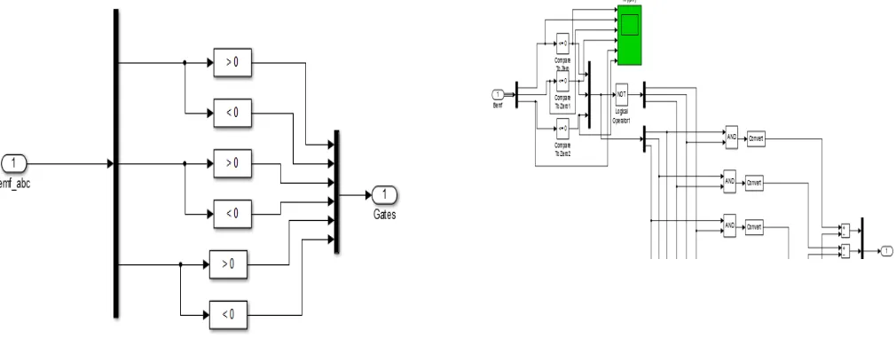
FIGURE 3.PROPOSED FOUR-SWITCH THREE PHASE INVERTER BRUSHLESS DC MOTOR DRIVE SYSTEMS
Among the implements, the three phase inverters have only four switches, the main description of these proposed inverter are reduction of switches and conduction losses. Until now, reduced components have been applied in AC induction motor drives, however now a day the Brushless DC motor drives are using due to its high power factor, high speed, high torque, simple control and lower maintenance. The Four-Switch Three Phase Inverter (Four-switch Three Phase Inverter) used in six commutation modes based on current control and Senso less control schemes. [10] developed Brushless DC motor drives with trapezoidal back electromotive force (EMF) using the Four-Switch Three-Phase Inverter. The four-space-vector scheme was used in the six commutation modes based on current control. In these Brushless DC drive configuration, the DC supply given to Fourswitch inverter it converts DC power to three phase AC power. In proposed method single phase to three phase converter back end consists of four switches (T1 to T6). In three phase Brushless DC motor, two phases A and B are connected to the two legs of the Four-switch Three phase inverter and the third phase C is connected to the centre point of the capacitor. Phase C is directly connecte to the Brushless DC motor, so the phase C current is not directly controlled [11]
+ + = 0
=−( + )
Therefore, phase C indirectly controlled by phase A and phase B. For Brushless DC motors with a trapezoidal back EMF, is required to produce a constant electric torque. The proposed voltage Pulse Width Modulation(PWM) scheme for Four-switch three phase inverter requires six commutation modes which are (X, 0), (1, 0), (1, X), (X, 1), (0, 1) and (0, X) [12]. Here “X” stands for Don’t care conditions.
III. EXPERIMENTALRESULTS
Figure 4Harmonic spectra of AC mains current, IIN (a) at 270 V AC mains and 100% load.
(b)at 170 V AC mains and 100% loa
Figure 5: Simulation model of proposed four-switch three phase inverter system
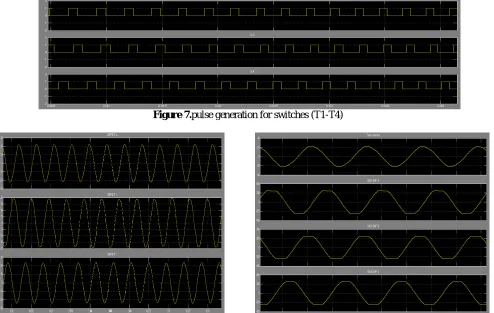
Figure 7.pulse generation for switches (T1-T4)
IV.CONCLUSION
Single stage PFC converters have gained importance due to simplicity in design and less amount of losses due less count of components. In this research, we significantly use sensorless control, so for angle position hall sensing fully avoided. Brush- less DC drives which is preferable for compact, low maintenance and high reliability system in order to reduce the mechanical strength so it proposed and convenient simulation results are carried out. In this the back electromotive force compensating and direct current controlling for brushless DC motor drives analyzed. In this scheme, the pulse width modulation is applied to high side switches of the converter. The power factor correction operation is carried out by using bridgeless zeta converter and PF controller.This proposed converter used sensorless control operation. There are no hall sensors, therefore, the system becomes robust, optimized design of the brushless DC. motor achieves higher efficiency and better speed, current is formulated.
REFERENCES
[1] Limits for Harmonic Current Emissions (Equipment input current ≤16 Aper phase), International Standard IEC 61000-3-2, 2000.
[2]N. Mohan, T. M. Undeland and W. P. Robbins, Power Electronics:Converters, Applications and Design, John Wiley and Sons Inc, USA,2003. [3] B. Singh, B. N. Singh, A. Chandra, K. Al-Haddad, A. Pandey and D.P.Kothari, “A review of single-phase improved power quality AC-DCconverters,” IEEE Trans. Industrial Electron., vol. 50, no. 5, pp. 962–981, Oct. 2003.
[4] B. Singh, S. Singh, A. Chandra and K. Al-Haddad, “ComprehensiveStudy of Single-Phase AC-DC Power Factor Corrected Converters With High Frequency Isolation,” IEEE Trans. on Industrial Informatics,vol.7, no.4, pp.540-556, Nov. 2011.
[5] A. J. Sabzali, E. H. Ismail, M. A. Al-Saffar and A. A. Fardoun, “NewBridgeless DCM Sepic and Cuk PFC Rectifiers With Low Conductionand Switching Losses,” IEEE Trans. Ind. Appl., vol.47, no.2, pp.873-881, March-April 2011.
[6] A. A. Fardoun, E. H. Ismail, A. J. Sabzali, M. A. Al-Saffar, “NewEfficient Bridgeless Cuk Rectifiers for PFC Applications,” IEEE Trans.Power Electron., vol.27, no.7, pp.3292-3301, July 2012.
[7] M. R. Sahid and A. H. M. Yatim, “An isolated bridgeless AC-DCconverter with high power factor,” 2010 IEEE International Conf.Power and Energy (PECon), pp.791-796, Nov. 29 2010-Dec. 1, 2010.
[8] T. Gopalarathnam and H. A. Toliyat, "A new topology for unipolarbrushless DC motor drive with high power factor," IEEE Trans. PowerElectron., vol.18, no.6, pp. 1397- 1404, Nov. 2003.
[9] V. Vlatkovic, D. Borojevic and F. C. Lee, “Input filter design for powerfactor correction circuits,” IEEE Trans. Power Electron., vol.11, no.1,pp.199-205, Jan 1996.
[10] Young-Kuk, L., Tae-Hyung, K. and Ehsani, M. (2003) On the Feasibility of Four-Switch Three-Phase Brushless DC Motor Drives for Low Cost Commercial Applications: Topology and Control. IEEE Transactions on Power Electronics,
18, 164-172. http://dx.doi.org/10.1109/TPEL.2002.807125[11] Lin, C.-K., Yu, J.-T., Fu, L.-C.and Liu, T.-H. (2012) A Sensorless Position Control for Four-Switch Three-Phase Inverter-Fed Interior Permanent Magnet Synchronous Motor Drive Systems. Proceeding of the IEEE/ASME InternationalConference on Advanced Intelligent Mechatronics (AIM), 1036-1041.
[11] Adauria, Y., Patel, A.N., Patel, V. and Patel, J. (2012) Simulation and Analysis of Three Phase Voltage Source Inverter Using Four Semiconductor Switches. Proceeding of the Engineering Nirma University International Conference onEngineering (NUiCONE), Ahmedabad, 1-14. [12] An, Q.T., Sun, L., Zhao, K. and Jahns, T.M. (2010) Scalar PWM Algorithms for Four-Switch Three-Phase Inverters. Electronics Letters, 46, 900-902.
[13] Eltrao de Rossiter Correa, M., Jacobina, C.B., Cabral da Silva, E.R. and Lima, A.M.N. (2006) A General PWM Strategy for Four-Switch Three-Phase Inverters. IEEE Transactions on Power Electronics, 21, 1618-1627
http://dx.doi.org/10.1109/TPEL.2006.882964
[14] Xia, H.L., Li, Z.Q. and Shi, T.N. (2009) A Control Strategy for Four-Switch Three-Phase Brushless DC Motor Using Single Current Sensor. IEEE Transactions on Power Electronics, 56, 2058-2066.