Power Quality Improvement Using Dynamic
Voltage Restorer
Hitesh Wankhede
1, Prof. H.R.Kulkarni
2UG Student, Department of Electrical Engineering, Sandip Institute of Engineering and Management, Nashik, India1
Associate Professor, Department of Electrical Engineering, Sandip Institute of Engineering and Management,
Nashik, India2
ABSTRACT: Now days, power quality is a major issue to deal. Modern equipment like computer, electric motors,
drives runs on precise power, so to maintain the quality of power for running of this equipment is very tough problem. Electronics equipment degrades the power quality by injecting the harmonics in it. So to improve quality of power supply to the load, Dynamic voltage restorer is used. Due to the power quality issues like Voltage sag and Swell, transient, flicker there is malfunction of electrical equipment. This power quality issues are completely compensated by using Dynamic voltage restorer. To reduce this voltage sag and swell, Dynamic voltage restorer is used and the results of DVR can be checked in MATLAB software by modelling and simulation technique.
KEYWORDS: DVR, power quality mitigation technique, MATLAB
I. INTRODUCTION
Electrical energy is the simple and well regulated form of energy, can be easily transformed to other forms. Along with its quality and continuity has to maintain for good economy. Power quality has become major concern for today’s power industries and consumers. Power quality issues are caused by increasingly demand of electronic equipment and non-linear loads. Many disturbances associated with electrical power are voltage sag, voltage swell, voltage flicker and harmonic contents. This degrades the efficiency and shortens the life time of end user equipment. It also causes data and memory loss of electronic equipment like computer. Due to complexity of power system Network voltage sag/swell became the major power quality issue affecting the end consumers and industries. It occurs frequently and results in high losses. Voltage sag is due to sudden disconnection of load, fault in the system and voltage swell is due to single line to ground fault results in voltage rise of un-faulted phases. The continuity of power supply can be maintained by clearing the faults at faster rate. Other power quality issues i.e. voltage flickering, harmonics, transients etc. has to be compensated to enhance the power quality.
Power electronic devices i.e. Distribution Static Compensator (D-STATCOM) and Dynamic Voltage Restorer (DVR) been recently used for voltage sag compensation and voltage swell compensation. In this project DVR is proposed which can protect the end-consumer load from any unbalance of voltage supply. It is a series compensating device, can maintain the load voltage profile even when the source side voltage is distorted.
II. SYSTEM DESCRIPTION
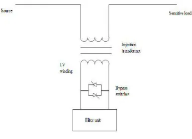
A) Protection Mode- In order to isolate DVR from the system during overload current caused by short circuit or large inrush current, bypass switches are provided. The current is supplied to the system using other path.
Fig 1.Protection Mode
B) Standby Mode- In this mode, Low Voltage winding of injection transformer is shorted. No switching operation occurs in this mode. In this mode, DVR injects the compensating voltage through injection transformer.
Fig 2.Stand-By Mode
C) Injection Mode- DVR in injection mode is carried out in following steps:
To find any voltage unbalance in the distribution network. This can be done by comparing the terminal voltage with load reference voltage. The difference is the desired voltage.
To initiate switching signals for Voltage Source Inverter (VSI), to track the desired voltage generated above by using satisfactory switching techniques such as SVPWM.
To filter harmonics by using passive filter, present in injected voltages.
To inject the filtered voltage using single phase transformers either connected in series with the load bus.
III. OPERATING PRINCIPLE
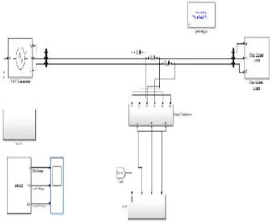
DVR is series connected compensating devices that restore the voltage profile at the sensitive loads under voltage unbalance. It is usually connected in the distribution network between Common Point of Coupling (PCC) and load. Fig.(b) shows the location of DVR in power system network. The disturbance in the system is detected by control scheme used which generates the triggering pulses for VSI. Passive filters are used to filter out the harmonic content of injected voltage. DVR injects the filtered output voltage through injection transformer.
Fig.3. Location of DVR
The basic structure of DVR shown in figure 4 consists of following blocks:
A. Voltage Source Inverter (VSI) - VSI converts fixed supply voltage stored into variable supply voltage. The converted voltage is boosted through the transformer. The rating is usually low voltage and high current since step up injection transformer is used. The output voltage of VSI should be; Balanced and pure sinusoidal, Same phase sequence as that of system, desired magnitude and for particular time duration, it should be instantaneous
C. Passive Filter- It filters out the harmonics present in the output of the VSI. It can be kept either at the inverter side or at the HV side of the transformer. If filter is placed at the inverter side, switching harmonics are prohibited to enter the injection transformer thereby reduces rating and voltage stress on it. If the filter is placed at HV side of injection transformer, harmonics can enter into HV side hence rating of transformer increases
D. Energy Storage Unit- During compensation, this unit provide the required real power to generate compensating voltage. Energy storage devices are lead acid batteries, flywheels, dc capacitors and super capacitors. Its capacity has great effect on compensation capability of DVR. The system with large disturbance requires real power compensation. DC to AC conversion required for batteries whereas AC to AC conversion required for flywheels.
E. Control circuit- Control circuit steadily observe the system. Its function is to detect any disturbance in the system done by comparing the supply voltage with reference voltage and generate the switching command signals for VSI in order to generate the compensating voltage by DVR.
IV.SIMULATION RESULTS AND CONCLUSION
The demand for quality power has become a challenging issue for industrial area and consumers. Among them voltage unbalance is considered as the major affecting problem leads to degradation in performance of electrical equipment’s. FACTS devices used for compensation are the best method to overcome such problem. Among them DVR considered the most efficient and cost effective.
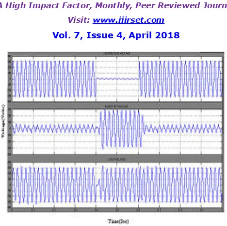
Fig.6. Compensated output voltage for voltage sag
Fig. 7. Compensated output voltage for voltage swell
Voltage unbalances such as voltage sag/swell are considered here. Voltage unbalance under both balanced and unbalanced condition is considered and simulation results are shown. Modelling and compensating technique used by DVR for compensating such unbalance are also presented. The simulation result shows that DVR compensate sag/swell effectively and provide good voltage regulation. The performance of DVR is satisfactory.
REFERENCES
[1]. V E. Babaei ,M. Farhadi Kangarlu, “Voltage quality improvement by a dynamicvoltage restorer based on a direct three-phase converter with fictitious DC link,” IET Generator Transmission Distribution, vol. 5, Iss. 8, pp. 814–823, 2011.
[2]. .D.RanjithPerera and S. S. Choi, “Performance Improvement of the Dynamic Voltage Restorer With Closed-Loop Load Voltage and Current-Mode Control,” IEEE Transactions on Power Electronics, vol. 17, no. 5, Sept. 2002
[3]. N. H. Woodley, L. Morgan, and A. Sundaram, “Experience with an inverter-based dynamic voltage restorer,” IEEE Transactions Power Delivery, vol. 14, pp. 1181– 1186, Jul. 1999
[5]. C. S. Chang, S. W. Yang, and Y. S. Ho, “Simulation and analysis of series voltage restorer (SVR) for voltage sag relief,” in Proceedings IEEE Power Electronics System Winter Meeting, vol. 4, pp. 2476–2481, Jan. 2000.
[6]. Y.W. Li, F. Blaabjerg, D. Mahinda Vilathgamuwa and P.C. Loh, “Design and Comparison of High Performance Stationary-Frame Controllers for DVR Implementation,” IEEE Transcations on Power Electronics, vol. 22, no. 2, Mar. 2007.
[7]. M. J. Ryan, W. E. Brumsickle and R. D. Lorenz, “Control topology options for single-phase UPS inverters,” IEEE Transactions Industrial Applications, vol. 33, pp. 493–501, Mar./Apr. 19 M. J. Ryan, W. E. Brumsickle and R. D. Lorenz, “Control topology options for single-phase UPS inverters,” IEEE Transactions Industrial Applications, vol. 33, pp. 493–501, Mar./Apr. 1997.
[8]. Chris Fitzer, Mike Barnes and Peter Green, “Voltage Sag Detection Technique for a Dynamic Voltage Restorer,” IEEE Transactions on Industry Applications, vol. 40, no. 1, Jan./Feb. 2004.
[9]. M. F. McGranaghan, D. R. Mueller, and M. J. Samotyj, “Voltage sags in industrial systems,” IEEE Transactions Industry Applications, vol. 29, pp. 397–403, Mar./Apr. 1993.