Transactions of the 17th International Conference on Structural Mechanics in Reactor Technology (SMiRT 17) Prague, Czech Republic, August 17 –22, 2003
Paper # 12-4
Large Explosion-driven Seismic Platforms (Theory, Practice and Prospects)
Viatcheslav Beliaev, Victor Vinogradov, Vladimir Sirro
Research Center of Capital Construction, St. Petersburg, Russia
ABSTRACT
Recently the problems of experimental assessing the operation and stability for diverse NPP objects and their elements (structures, building constructions, systems, components etc.) under the conditions of destructive earthquake-type effects have become crucial. The complex of ground shake tables (these tables have been under operation in Russia for more than 20 years) makes it possible to reproduce the dynamic loads caused by such effects on the basis of explosive technology. The complex in question incorporates a set of seismic platforms with load-carrying capacity up to 800 tons.
According to the technology developed such reproduction of the necessary loading conditions of the objects under study is carried out due to energy effect of firing the explosive charges on the bearing structures of the test stands and further transformation of the kinematic processes with the help of special forming devices. In order to set the necessary direction of the test stand structures movement the blsting of explosive charges can be carried out both in the soil (directly under the test stand or on the side of it), and in the special load actuators, which are installed on the platform and creat jet power (recoil force). As forming devices for transformation of the seismic platform kinematic processes into the required test parameters the elements of various type and design (pneumatic, hydraulic, pneumo-hydraulic, mechanical etc) are used.
Chosing the weight and the quantity of the explosive charges, conditions of their arrangement (placement distance and depth, installation in the actuators, etc), setting the firing sequence, as well as application of the forming devices with certain characteristics, changing the devices layout and operation mode etc. ensure forming the loads of the required type, rate and frequency content.
By now with the use of this seismic explosive technology we had tested seismic stability of several structures including seismic isolated buildings, equipment, models of hydraulic engineering works and floating objects.
The paper presents the main provisions of design procedure for evaluating the power effect under internal explosive charges explosion, possibility to obtain necessary dynamic responses with the help of seismic platforms is justified.
KEY WORDS: multicomponent seismic platforms, explosive drive, ground base, programmable explosive blasting, additional elastic-dissipative connections
INTRODUCTION
World and Russian practice knows application of various devices as the drives for a test bed. Most of them permit to simulate impulsive or damped sinusoidal motion of a platform with a relatively small object. Requirements for seismic stability research of NPP large-sized building constructions and equipment are more complicated. As a consequence, large programmable seismic platforms include servo-driven hydraulic tappets. A special place among this known test facilities, designed to check seismic stability of large objects is occupied by the complex of ground seismic platforms. Both the general principle and the structure of these seismic platforms differ from those used in mechanical devices.
PRINCIPLE AND MAIN STRUCTURAL DESIGN FOR GROUND SEISMIC PLATFORMS
High energy potential of explosives, possibility to simplify the technology of experiments preparation and to decrease their cost had promoted widespread use of blasting methods at field testings of object seismic stability. Simulation of real earthquake wave pattern on the surface of sufficient large area was ensured by multiple-row short-delay linearly distributed blastings in vertical holes. The experience suggests that preparation of such experiments appears to be a rather labour-consuming and long-term procedure. Among the shortages of this method are complexity of active vertical loads simulation and incompletness of filling the low-frequency part of the test load input spectrum. Obvious advantage of this method is possibility to study interaction of building foundation and soil.
properties of explosives to initiate the motion of a test table with the object from the given law with the help of pulse explosive actions.
Possibility to simulate ground acceleration at earthquake by application of pulse succession has been considered in a number of works. Among the other things it was shown, that for receiving the required parameters at the linear system output at the time instants αi the pulses can be applied instead
of continuous function, and the value of output signal and time instants αi can be calculated.
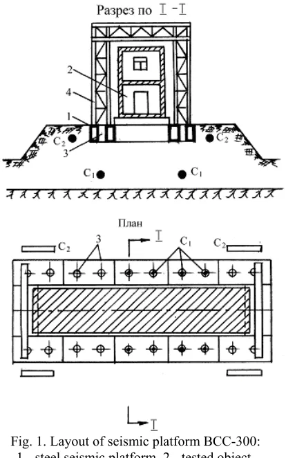
Russia’s test complex of seismic platforms includes wide range of devices for dynamic and static testings of building constructions and equipment for natural and man-triggered loads, including seven ground seismic explosive stands located out of doors. The main structural component of seismic explosive stands is a rigid steel or reinforced concrete seismic platform. Instead of known engineering solutions for large programmable seismic platforms in this case the seismic platform is located on the sand layer with underlaying monolithic rock. The construction of ground seismic platforms shows a variety of types, it can be: a frame of rectangular shape (Fig.1), an open-topped case of rectangular (Fig.2) or cylindrical (Fig.3) shape with console lugs along the perimeter. The common feature for all this versions is structure burying into sandy ground. In the ground around the seismic platforms spherical or lengthened blasting charges are to be placed under bottom, under consoles, along the lateral areas of seismic platforms.
Thus, there is a theoretical possibility to reproduce the required motion of test shake table by way of sequential application of impulses of force, for which both time intervals and intensity had been calculated. It is to be noted, that in spite of obviously idealized nature of this theoretical problem setting (linearity of oscillatory system, function regulariry), this approach can be considered as the princilple basis for construction and work of the complex of large seismic platforms with seismic explosive drive in Russia.
Fig. 1. Layout of seismic platform ВСС-300: 1 - steel seismic platform, 2 - tested object, 3 - openings for blasting charges, 4 - portal frame,
С1, С2 - blasting charges
Under repeated programmable camouphlet blasting of relatively small charges and a required impulsive loading of structures is generated, in response to which the seismic platform with tested object execute one-dimensional, plane or spatial motion with parameters which correspond to the test goals. The main mass-dimension characteristics of ground seismic explosive stands are listed in the table 1. As we can see from the table, overall dimensions of existing seismic platforms permit to conduct seismic stability experimental testing for wide nomenclature of buildings and equipment.
Table 1. Mass-dimension characteristics of ground seismic explosive stands Index of the stand Rated load-carrying capacity,
H/W Plan dimensions *) of seismic platforms, m
length width
ВСС -300 300 30 12
ВСС -100 100 16,8 8,1
ВСС -70 70 11,3 5
ВСС -40 40 7,6 4,7
ВСС -40М 40 7,6 4,7
ВСС -20 20 5,6 5,6
ВСС -80ЦП 80 diameter 7,0
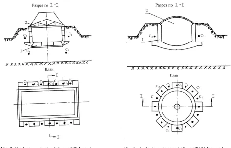
Fig. 2. Explosive seismic platform-100 layout: 1 - steel seismic platform, 2 - steel truss,
С1, С2 - blasting charges
Fig. 3. Explosive seismic platform-80ЦП layout: 1 - reinforced concrete seismic platforms, 2 - detachable
steel covering, С1, С2 - blasting charges
In addition the mutual arrangement of two same-type explosive seismic platforms ВСС-40 and ВСС-40М ensures conditions for testing of long-size (50-70 m and more) objects. When filling the internal cavity of the platform ВСС-80ЦП with soil and/or water it is possible to study the interaction of inserted (embedded) object, for example, a pile or a support, with environment under seismic input.
Operational experience of ground seismic platforms had shown, that if we want to extend the range of the conditions reproduced it would be appropriate to use transforming elastic elements, which are installed in special ground cavities under the bottom of the platform and/or additional test table, which is to be placed on the platform and connected with it by means of elastic - dissipative devices.
TEST CONDITIONS FOR GROUND SEISMIC PLATFORMS
On each of the platforms three of main test conditions are realized:
“seismic shock test condition”, which reproduce the shaking of building constructions and equipment mounting attachments under effect, for example, of close industrial explosions;
“rigid seismic condition”, which simulates/ among the other things, seismic vibration at high (12 m and above) marks of buildings and constructions, as well as in accordance with the laws of similarity of real structure models;
“soft seismic condition”, simulating ground and construction foundation motions in conditions of various earthquakes.
In this condition in accordance with test purposes the support block motion of the object under study are in the form of spatial, plane or one-dimensional non-stationary vibrations. The limits of changes of characteristic peak values of load inputs, which are reproduced on the stands in frequency domain [0; 200 Hz], are presented in the Table 2.
Table 2. Characteristic peak values of load inputs
Type of loading condition
Accelerations (g) along the axes
Speeds (m / с) along the axes
Displacement (m) along the axes
Durations of
oz ox (oy) oz ox (oy) oz ox (oy)
Shock-seismic +30/-10 40 +3/-1 3 +0,5/-0,2 0,5 up to 1,0
Rigid-seismic 10 10 2 2 0,5 0,5 up to 5,0
Soft-seismic 2 2 1 1 0,7 1,0 up to 30,0
Besides observing the amplitude-time limitations in the ranges, specified in the Table 2, the processes realized ensure the fulfilment of requirements to amplitude-frequency composition of vibrations of the stand test table, for example, filling the standard spectrum or individual target spectra.
The performance of experiments under "seismic shock" conditions is possible in the most simple complete set of equipment - the object tested is directly placed on the seismic platform, which is rest on sandy ground.
The required type of platform motion (vertical, horizontal, plane, azimuth) and necessary values of its peak and time characterisic are ensured by corresponding selection of number, shape (concentrated, lengthened) and weight of charges, their location, distances to the stand bottom and walls, by value of charges burying into the soil, as well as by the sequence of camouphlet blastings and time intervals between them. Thus, we have at our disposal a considerable set of parameters, which permit to change the conditions of platform motion in sufficient wide range.
Physical essence of the phenomena, occurring under camouphlet charge blasting in soft soil has been studied adequately. In accordance with experimental data the pressure variation in soil can be approximated in the form of exponential relationship
P(
r
, t) = Pmax (r
) exp
−
−
)
(
2
r
t
t
iτ
(1)For specific impulse i the following expression is true:
i = k2 ro (1/
r
) µ2 (2)In (1), (2) we use the following designations: Pmax (
r
) = k1 (1/r
) µ1 ,τ
(
r
)
= 1.15 (k2/k1) r0r
(µ1 - µ2) ,)
(
r
τ
ti –time of wave arrival to the ith surface point of seismic platforms,τ
(
r
)
k1, k2, µ1, µ2 - coefficients,dependent on soil properties, in our case µ1 = (3,0 ÷ 3,3), µ2 = 1,5, k1 = (4,5 ÷ 7,2)⋅104 kg⋅sm –2, k2 = (50 ÷ 62) kg⋅s⋅
sm –2.
The pressure, acting on the fixed obstacle, located at an angle α to the wave front, is calculated from the formula
Pпр(
r
, t) = Kотр P(r
, t) (3)where Kотр = 2(cos2α + (η/2 )sin2α), η = 0,35 ÷ 0,5.
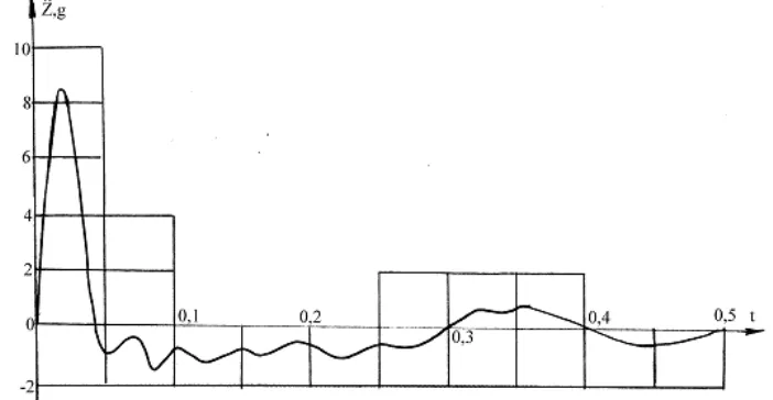
After initial pulse of sequential loading pressure of seismic platforms surface a wave train reflected from the rock bed occurs and complicates the pattern of forced vibrations of seismic platforms and tested object.
Fig. 4. The plot of vertical accelerations of seismic platforms under simultaneous charges blasting
Fig.5. Shock spectra of accelerations: Fig.6. Shock spectra of displacements: 1 - with a rock bed, 2 - without any rock bed 1 - with a rock bed, 2 - without any rock bed
Forming the seismic platform motions which are required in accordance with testing purposes is reached by selection of blasting charges mass, type of explosive (trotyl, ammonal, powder etc), shape of charge (concentrated, lengthened), depth of their deposition, distance from a seismic platform, time sequence of blasting. Determination of these parameter values is based on the results of prognostic calculations with introduction of a series of empirical dependences. Thus using accumulated operational experience makes it possible to compensate inavoidable idealization of mathematical description of seismic platforms loading and to take into consideration, among the other things, the influence of climatic factors, related to placement of testing machine in open space, inhomogeneity of soft soil stiffness properties due to the effect of previous blastings etc Reusing the seismic platforms under seismic shock conditions shows that the variation of controllable motion characteristics does not exceed 10-15% for accelerations and 10% - for displacements.
Rigid seismic test conditions (see Table 2) are realized on seismic platforms with seismic explosive drive in two modes with the aid of additional structural member. In the first case cavities are made in the ground under platform bottom and along its surface area, these cavities are not falling in the camouphlet area of blasting charges. The cavities with preliminary lock strut contain pillow-type pneumatic elements (Fig.7).
Fig. 8. Dependence of pneumatic element axial strengthening from the value of lock strut and initial
pressure
Fig. 9. Dependence of pneumatic element shear strengthening from the value of displacement and initial
pressure
The type of dependence of axial force from the value of lock strut and initial pressure as well as shear load from the value of displacement and initial pressure for the pneumoelements used is shown in Fig.8 and 9 respectively. Seismic platforms motion is formed under explosive pressure pulses, as well as under total reaction of surrounding soil and pneumoelements. As a result the duration of seismic platform vibrations increases and their frequency range expands.
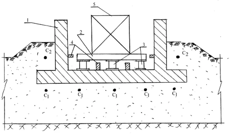
In the second case the similar effect is reached by placing intermediate test table with an object on the seismic platforms. Test table is located on supports with the required elastic-dissipative characteristics, for example, on pneumatic, hydraulic or spring dampers (Fig.10). In addition blast devices can be used. Energy of explosive blastings actuates the seismic platforms, which, in turn, excites vibrations of the test table on elastic supports. The type of vibration process of the table with an object to be tested and its duration depend on number and rate of collisions with blast devices. While selecting characteristics of supports and blast devices, the value of initial gap between blast devices and test table, as well as parameters of charges basting we manage to realize rigid seismic object loading condition.
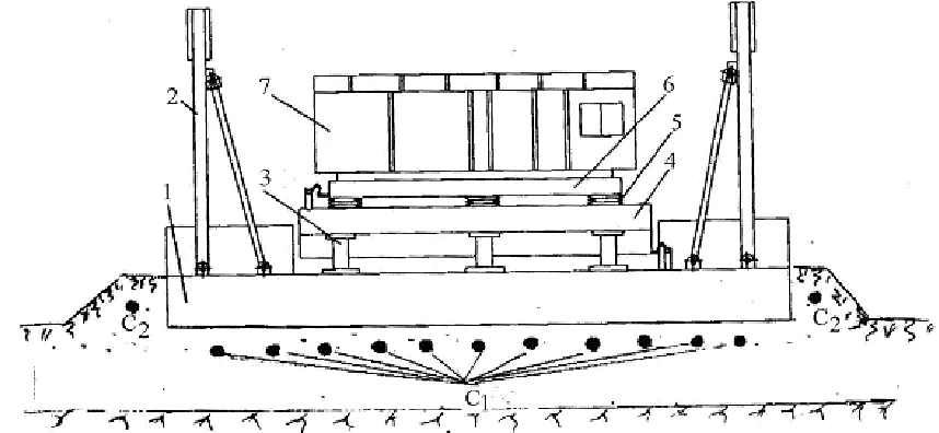
The most labour-consuming is formation of seismic platform motion, equivalent to severe earthquake action at the level of soil and foundation surface (soft seismic condition). Primarily this is due to the fact that usually we need to reproduce the process of multicomponent vibrations of the tested object supports, duration of this process is 30 seconds and over on the provision of filling broad-band frequency spectrum, including the area of low (0,5 - 1,5 Hz) frequencies. Displacements of object supports can be 0,4 - 0,5 m and above. In this case in addition to test table on the seismic platform an intermediate platform is used. This platform is installed on the test table with the help of pliable supports with nonlinear stiffness characteristic. The explosive seismic platform BCC-300 with two-rotor transforming device is shown in Fig.11. Similar structural seismic platform complication increases the volume and cost of works for test preparation. However if we have a set of removable platforms and pliable supports the preparatory phase can be performed on short notice.
Fig.11. Layout of explosive seismic platform BCC-300 under soft seismic test condition: 1, 2 - portal frame, 3 - test table support, 4 - test table, 5 - intermediate platform support, 6 - intermediate platform, 7 - tested object
The good points of programmable seismic platforms with hydraulic drives is higher level of control and accuracy of the test table preset motion reproduction. We should note, that it is logically proven to assume prognosis accuracy equivalence of ground or foundation motion laws of the tested object at earthquake and their simulation on seismic platforms at its seismic stability testing. Under such approach some variation of vibration parameters of the test table is quite admissible and has its physical justification.
DIRECTIONS OF FURTHER MODERNIZATION OF THE PLATFORMS
Solving the problem of simulation of seismic ground and foundations motions of large (20 seconds and more) duration had required further modernizing seismic platform structure. Thus a rather effective facility appeared to be setting of powder load generators on lateral area of seismic platforms and/or test table (intermediate platforms). Attachment of generators provides possibility to change the angle with horizontal plane for controlling the vertical and horizontal motion component rate.
Fig 12 shows the layout of the explosive seismic platform BCC-40 which was modernized in such a manner. On two consoles of the seismic platforms load powder generators are installed, under other consoles vertical pneumoelements are located. Test table with an object is placed on support rollers. In the gaps between the test table and the seismic platforms lateral pneumatic elements with devices of static position fixing and displacement restraint releasing are placed. In the starting position a preliminary test table shift was carried out. Once a release device had come into action the table under the action of lateral forces difference executes additional slowly damping sinusoidal motion. The main hydraulic actuators which initiate the motion of test table with an object, are programmable destructions of blasting charges in the ground and powder charges in load generators.
Fig.12. Layout of modernized explosive seismic platform BCC-40: 1 - seismic platforms, 2 - test table, 3 - tetsted object, 4 - seismic platform consoles, 5 - powder load generator, 6 - pneumoelements,
7 - support rollers, 8 - release device
This plant allows for of full-scale check of dynamic efficiency and operational characteristics of seismic isolation systems for buildings and constructions. For this purpose special positions for various seismic isolation and damping devices are provided on the intermediate platforms. In this condition in three-dimensial structure we can place equipment with mass up to 300 t, including real layout, conditions of simulating the floors and walls seismic vibrations which correspond to full-scaled. Thus, general load-carrying capacity of the plant CC 500/300 is 800 t. It is to be noted, that the values of load-carrying capacity of other plants, listed in the Table 1, relate to seismic shock condition of seismic platforms work. In this case structures motion acceleration is 30-40 g and active inertial load are maximal. The possibility to increase the platforms load-carrying capacity when switching to rigid seismic and, especially, soft seismic test conditions is quite evident.
CONCLUSIONS
Complex of seismic platforms with seismic explosive drive has been under construction for more than 30 years, its development is still in progress. Thus CC 500/300 had been brought into use in 1994, explosive seismic platform BCC-70 in 1999. Nowadays this experimental seismic stability complex for testing building constructions and equipment is the largest one in Russia. Its place is unique in the world. The developed technology of seismic input simulation makes it possible to test seismic stability of objects with mass from tens of kgs up to 800 t.