Knowledge-Based Image Coding Technique
Adnan
M.
Alattar
Center for Communication and Signal Processing
Department of Electrical and Computer Engineering
North Carolina State University
Raleigh, North Carolina
November 1989
Alattar, Adnan Mohammed. Knowledge-Based Image Coding. (Under the direction of Sarah A. Rajala)
iii
BIOGRAPHY
Adnan Mohammed Alattar was born in Khan Younis, Palestine, on November 25, 1961. He received his B.S.E.E. from the University of Arkansas at Fayettevillein
1984 and his M.S.E.E from North Carolina State University at Raleigh in 1985.
During his graduate studies at North Carolina State University, he was employed as a research assistant in the Center for Communications and Signal Processing (CCSP) and as a teachingassistant intheDepartmentof Electrical andComputer Engineering.
ACKNOWLEDGEMENTS
The authorisgrateful to his advisor Dr. S. A. Rajala for her guidance and support at all stages of this research. He would also like to thank Miss Marcie L. Lucas for editing this manuscript
v
TABLE OF CONTENTS
LIST OF TABLES ix
LIST
OF
FIGURES x1. INn.ODUcnON
11.1. Traditional Image Coding 4
1. 1. 1. Pulse COOed Modulation 4
1.1.2. Transform Coding 6
1.1.3. PredictiveCoding 8
1. 1.4. Interpolative and Extrapolative Coding 10
1.1.5. BinaryCoding 11
1.2. Second Generation Image Coding 12
1.2.1. Perception-Based Image Coding 13
1.2.2. Segmentation-Based Image Coding 15
1.2.3. Model-Based Image Coding 17
1.3. Outline of me Disserta.tion 19
2. KNOWLEDGE-BASED IMAGE CODING
212.1.
General Knowledge-Based Systems 222.1.1. Knowledge-Based System Interfaces 23
2.1.2. The Knowledge Base 24
2.1.3.
The Inference Engine · ·· · · ··262.2.
Computer Animationand
Image Coding28
2.2.1. Conventional Animation · . · ·· · · · ·· . · ·· · · · ·· · .. · · ··29
2.2.2. Rotoscoping 31
2.3. Composing Pictures from Pieces of Other Pictures · · 32
2.4.
A
General Methodology for Knowledge-Based Image Coding34
2.5. The Structure of the Knowledge-Based Image Codec37
2.5.1.
Knowledge-Based Image Coder37
2.5.2.
Knowledge-Based Image Decoder40
2.5.3. General Requirement for Applying Knowledge-Based
ImageCodingTechniques 43
3. A MODEL-BASED ALGORITHM FOR FACIAL FEATURE
EXTR.ACI10N 44
3.1. Introduction 44
3.2. A Model for Head and Shoulders Images 46
3.3. Facial Features Extraction Algorithm 54
3.4.
Implementation and Simulation Results63
4. KNOWLEDGE-BASED IMAGE CODING TECHNIQUE FOR STILL
PICTURES 71
4.1.
Mug-Shot Images as an Application 714.2. Recognition of Faces
72
4.2.1.
Human Face Encoding72
4.2.2.
Huma.n Face Storage74
4.2.3.
Human Face Recall74
4.2.4.
Human Face Recognition75
4.2.5.
Knowledge-Based Image Coding Technique forHead
and Shoulders Images and Face Recognition 76
4.3.
Primitives
of Headand Shoulders Images
78
vii
4.5. Primitive Matching 82
4.6. Primitive
Projection
854.7. Prototype Image 85
4.8.
Post-Processing86
4.9. The Databa.se 87
4.10. CodingandDecoding a Head and Shoulders Image 93 5. KNOWLEDGE-BASED IMAGE CODING TECHNIQUE FOR TIME
VARYIN"G WAGE SEQUENCES 98
5.1. Video Teleconferencing and Picture Phone Images as Applications 98
5.2.
Coding and Decoding a Time-Varying Head and Shoulders ImageSequence 99
5.3.
On-Line Database Construction 1055.4. Accumulation of Errors and Frame Refreshment 107
5.5. Buffer Requirements and Control 107
5.6.
Parallel/Pipeline Implementation of the Knowledge-BasedTeleconference ImageCodec ...•...110 6. IMPLEMENTATION, SThWLATION, AND PERFORMANCE ANALYSIS
OF TIIE KNOWLEOOE-BASED IMAGE CODEC 114
6.1. Analysis of the Input Head and Shoulders Image Sequence 114
6.1.1. Noise Analysis 115
6.1.2. Motion Analysis of Full Frames of the Image Sequence 116 6.1.3. Motion Analysis of Sub-Areas of the Frames of the
Image Sequence ··· .118
6.2. Implementation and Simulation Results of the Knowledge-Based
6.2.1. Facial Feature Location and Extraction 122
6.2.2. Coding and DecodingStill Pictures 131
6.2.3. Coding and Decoding Time-Varying Image Sequences 138 6.2.4. Investigation of Mis-Projection Error 144
6.2.5.
Image
QualityMeasures 1476.3. Computation Requirements 151
7. CONCLUSIONS AND SUGGESTIONS 155
7 .1. Conclusions 155
7.2. Suggestions for Further Study 156
8. LIST OF REFERENCES 158
9. APPENDICES 169
Table 6.1 Table 6.2 Table6.3
Table6.4 Table 6.5
ix
LIST OF TABLES
The Parameters of the Fitted Ellipses 128
Comparison Between Closed Form and Iterative Curve Fitting 129 Status of the Eyes, Nose, and Mouth in Each Frame of the Image
Sequence 140
Rating Scales for Subjective Image Quality Evaluation 148 Computation Requirements for the Knowledge-Based Image
LIST OF FIGURES
Figure 1.1 Figure 1.2 Figure 2.1 Figure 2.2 Figure 2.3 Figure 3.1 Figure 3.2 Figure 3.3a Figure 3.3b Figure 3.3c Figure3.4 Figure 3.5 Figure 3.6 Figure 3.7a Figure 3.7b Figure 3.7c Figure 3.7d Figure 3.7eFigure 3.8
The I.mage COOing Process 2
Image Formation and
Human
Perception18
Knowledge-Based System 23
Knowledge-Based Image Coder 39
Knowledge-Based Image Decoder 42
Head Rotation Angles with Respect to the X, Y, and Z Axes 48
Head Model for Head and Shoulders Images 50
Flowchart for Edge Detection 56
Flowchart for Head Contour Extraction 57
Flowchart for Head Feature Location 58
Sobel Operator's Templates 62
Chen et.aleTemplates 63
128x128 Input Image
M
The Edge Image of Fig. 3.6 65
The Thresholded Image of Fig. 3.7a 66
The Thinned Image of Fig. 3.7b 66
The Outer Most Head Contour of Fig. 3.7c 67
The Estimated Ellipse for the Head Contour in Fig. 3.7c 67
The
Estimated Locations of the Four Major Facial Features ofFig. 3.6 · ···· 68
Figure 3.9
The Adjusted Locations of the Four Major Facial Features of
Figure 4.1 Figure 4.2 Figure 4.3 Figure 4.4 Figure 4.5 Figure 5.1 Figure 5.2 Figure 5.3 Figure 5.4 Figure 5.5 Figure 6.1 Figure 6.2 Figure 6.3 Figure6.4 Figure6.5 Figure 6.6 Figure 6.7 Figure 6.8 Figure 6.9 Figure 6.10 xi
Filter Set for Facial Feature Extraction · · . 81
Neural Network for Wisard · 84
Structure of the Database for Head and Shoulders Images 88 Knowledge-Based Coding Process for Still Pictures 95 Knowledge-Based Decoding Process for Still Pictures
97
Knowledge-Based Coding Process for a Time-Varying ImageSequence 103
Knowledge-Based Decoding Process for a Time-Varying Image
Sequence
104-Structure of the Database for Time-Varying Head and Shoulders
Image Sequence 106
Parallel and Pipeline Implementation of the Knowledge-Based
Coder 111
Parallel and Pipeline Implementation of the Knowledge-Based
Decoder 113
Frame 11 in the Head and Shoulders Image Sequence 114 Frame 20 in the Head and Shoulders Image Sequence 115
Noise Probability Density Function 116
Motioninthe
Head
and Shoulders Image Sequence117
Motioninthe Nose and
Left Eye Area
119
Motionin
the
Nose and Right EyeArea
120Motion in
the
Mouth Area ...•..•.••...••...•...•...120Motion inthe Chin Area 121
The Edge Image of the Image in Fig. 6.1 123
Figure 6.11 Figure 6.12 Figure 6.13 Figure 6.14 Figure 6.15 Figure 6.16 Figure 6.17 Figure 6.18 Figure 6.19 Figure 6.20 Figure 6.21 Figure 6.22 Figure 6.23 Figure 6.24 Figure 6.25 Figure 6.26
The Thresholded Edges of the Edge Image of Fig. 6.9 124
The Edge Image of Fig. 6.11 After Thinning 125
The Outermost Contour of the Head in Fig. 6.1 126 The Best Fit Ellipse for theHead Contour of Fig. 6.13 126
Convergence Error vs. Number of Iterations 127
Locations of the Estimated Facial Features 130
The Adjusted Locations oftheFacial Features 130
The Hierarchical Structure of the Database 132
An Image for Constructing a Prototype Image 134
A Prototype Image Constructed from the Image of Fig. 6.18 134
Output Image with 1092: 1 Compression 136
Previous Frame 141
The Output Image with 1638:1 Compression 142
Eye Shifted (3,2) and Mouth Shifted (3,-2) 145
Nose Shifted (-4,-2) and Mouth Shifted (3,3) 146 Eye Shifted (-5,-3), Nose Shifted (-4,-2), and Mouth Shifted
1
CHAPTER 1
INTRODUCTION
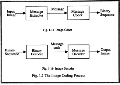
Although digital representation of pictures has several advantageous features such as processing flexibility, relatively errorless transmission, ease of storage and retrieval, and compatibility with digital computers and digital networks, it has the disadvantage of requiring a very large number of bits. For instance, over 2 million bits are needed to represent a picture with 512x512 pixels when each pixel is quantized to one of 256 gray levels. Transmitting or storing such a large amount of data requires a large bandwidth or large storage space, which may not be available. The consequence of these two requirements is the high cost involved. Fortunately, image data redundancy can be reduced before transmission or storage, allowing reductions in the bandwidth and storage requirements.
Input Image
Message Message Message
...
...
...
....
Extractor
....
Coder....
Fig. 1.la Image Coder
Binary Sequence
Fig.1.1b ImageDecoder Fig. 1.1 The Image Coding Process
l---I~.Output
Image
Other factors further distinguish between first and second generation techniques. First generation techniques consider the individual pixel values as the messages [1,2]. These values are algebraically manipulated to reduce the statistical correlation between them, and are thencodedand transmitted. Popular coding techniques such as pulse coded modulation (PCM), transform coding, and predictive coding areinthis category. Second generation techniques [5], however, use global image features as messages, and therefore
3
Generally speaking, first generation techniques produce better image quality [1,2] than second generation techniques, but second generation techniques achieve higher compression ratios [5,6]. While first generation techniques achieve a maximum compression ratio of less than 20:1,second generation techniques achieve compression ratios on the order of 50: 1.These compression ratios are still insufficient for most modem applications. For instance, digital transmission of monochrome video signals over a low-bit-rate channel of
64
Kbits/sec or less requires a compression ratio over 750: 1 [7]. When attempting to achieve such a compression ratio with existing image coding techniques, unacceptable image quality maybeobtained.In this research effort, a new image coding technique is developed, which achievesanextremely high compression ratio while producing good image quality. The new technique is called knowledge-based image coding, and may be thought of as a generalization of segmentation-based techniques. In this new technique, a priori knowledge about the image is used to break the image into its primitives, which are chosen to represent the features of the image. Although, such
a
priori knowledge is available for most applications, its use has long been overlooked. Diverse fields such as computer animation, the art of drawing,expert
systems, and database systemsare
incorporated intoboththe coding and decoding stages of the new technique,asdiscussedinchapter 2.
1.1. Traditional Image Coding
Most traditional image coding techniques are based on information theoretic principles, and usually depend on local, pixel-oriented features of the image. The goal of these techniques is to exploit the statistical redundancy among the pixels in order to achieve data compression. Five distinct types can be identified among traditional image coding techniques, namely, pulse coded modulation, transform coding, predictive coding, interpolative and extrapolative coding, and binary coding [1,2,3,4]. These are discussedin the following five subsections.
1.1.1. Pulse Coded Modulation
Pulse Coded Modulation (PCM) is the most basic type of image coding [8]. Itisa by product of representing analog images in digital format. In this technique, an analog image signal is spatially filtered and sampled on a rectangular grid, which is typically 512x512. Then, the signal amplitude is quantized and assigned a code word of fixed or variable length, usually 8 bits. At the receiver, the received code word is decoded to reconstruct the original amplitude.
5
quality can be obtained using 3 bits/pixel, more than 5 bits/pixel are usually used to adequately reduce the quantization noise, which manifests itself in the image as snow.
Vector Quantization (VQ) [10] may be considered a generalization of PCM in
which adjacent pixels are grouped into vectors to serve as the messages tobe coded and transmitted. The pixels in each vector are quantized together. Usually, the quantization process is done by replacing the vector with a suitable choice from a pre-existing set of quantized vectors; this set is called the codebook. The design of an optimum codebook is not an easy task. Usually, a training set of images is used to generate vectors suitable for the codebook. Suitable vectors are those that minimize the average quantization errorin
the class of images to becoded. One method of generating the codebook is called the Lloyd algorithm [11]. It requires an initial codebook, which is iteratively updated until no significant reduction in the average quantization error is obtained. A more efficient algorithm, which does not need an initial codebook, is called the nearest neighbor algorithm [12]. It starts with the entire training set of vectors and reduces it to the desired sizebyiteratively merging pairs of closely-valued vectors into single vectors. The value of each new vector is equal to the mean of the vectorsinthe merged pair.
The major advantage of VQ is the simple structure of the receiver, which consists only of a duplicate codebook. The disadvantages include the design complexity of an
optimumcode book and the fact that images dissimilar to thoseinthe training set may not
1.1.2. Transform Coding
In transform coding [13], a linear transformation is used to transform an input image to another domain, where the correlation among the transformation coefficients is less than that among the original pixels, and where the energyisconcentrated in a few of the coefficients. The values of the high-energy coefficients are quantized and coded as messages for transmission; the other coefficients are discarded. At the receiver, the inverse transform is performed on the received coefficientstoreconstruct a replica of the original image. However, the quantization error and the loss of energy in the discarded coefficients produce image distortion.
Zonal sampling and threshold sampling [1] are used to select the high energy coefficients.Inzonal sampling, the coefficients in a specific zone are selected, regardless of their energy. Inthreshold sampling, only those coefficients with magnitudes above a certain threshold are selected. The performance of threshold sampling is better than that of zonal sampling, but because of the overhead information regarding the location of the selected coefficientsin threshold sampling, more compression is achieved with zonal sampling than with threshold sampling.
7
performance of the KL transform. In fact, these transforms achieve a bit rate of slightly less than 1 bit/pixel, which can be improved 25% by using adaptive transform coding [19]. Adaptation in transform coding includes changing either the way the coefficients are quantized or the typeof transform used.
A special typeof transform codingisSingular-Value-Decomposition (SVO) [20]. This transform is optimum for a particular image. The vectors of the SVO of the input image are used as the transformation basis vectors. Since these vectors vary from one image to another, they have to be transmitted in addition to the transformation coefficients. This reduces the achievable compression ratio and the importance of the SVD as an image compression technique.
Transform coding can be considered a special case of a more general class called sub-band coding [21].
In
sub-band coding, filter banks are used to divide the image into sub-bands that are quantized and coded separately. Normally, Quadrature Mirror Filters (QMFs) are used to divide the image into its sub-bands. The use of the Q?vfF's eliminates possible aliasing error between the sub-bands. At the receiver, inverse filter banks are usedtoreconstruct the original image. The performance of the sub-band coder at a rate of 0.67-2.0bits/pixel is shownin[21] to bebetter than that of theDcrand VQ coders with subjectiveerror properties, and the complexity of the sub-band coder is comparable to1.1.3. Predictive Coding
The third class of traditional image coding techniques is predictive coding. It exploits the strong spatial and temporal correlation between adjacent image pixels to predict the value of the current pixel from the values of previously encoded pixels. The prediction error serves,inthis case, as the messagetobetransmitted. Since the prediction error is statistically less correlated than the original pixels, and its effective dynamic range is smaller, it can be quantized more coarsely to achieve image compression.
Similarly, the prediction of the current pixel value from previously decoded pixels occurs at the receiver. The value of the current pixel is reconstructed by adding its transmitted error to its predicted value. In general, the prediction can be linear or non-linear, and one-dimensional or two-dimensional. One-dimensional prediction utilizes only those pixels in the same line as the pixel being predicted, while two-dimensional prediction utilizes pixels in the previous lines as well.
9
A higher compression ratio can beachieved for time-varying image sequencesby using interframe prediction. Interframe prediction uses pixels from the current or previously transmitted fields or frames to predict the value of the current pixel. Aspecial type of interframe predictive coder utilizes conditional replenishment [27]. The structure of this coder is very simple; the pixels in the current frame are subtracted from those in the previous frame and the difference is thresholded, quantized, and transmitted. When the motion in the image sequence is very low, the performance of conditional replenishmentwith 1 bit/pixel is comparable to that of an 8-bit PCM coder. However, the performance is seriously degraded when the motion is vigorous.
Some very important predictive coders are known in the literature as motion compensation coders. These coders are specially designed for coding time-varying image sequences, where motion between frames is assumed small and translational. When a non-compensated predictive coder is used between the frames of such sequence, a large prediction error occurs. Motion compensation coders reduce this errorbyfirst estimating a displacement vector for each pixel in the image, in order to find its corresponding location in the previous frame; they then predict the current pixel valuebasedon the pixel valuesin a neighborhood of the corresponding location in the previous frame. There are two basic methods for estimating the displacement vector: Pel Recursion, and Block Matching[3].
In
Pel Recursion the motion is estimated for each pixelbasedon the spatialand
temporal gradients, but for Block Matching, the image is first divided into small blocks and a displacement vector for each block is estimated by finding the best match ofTransform and predictive coders can be combined into hybrid coders to achieve high compression ratios at 0.5 bits/pixel. In these coders, the image is spatially transformed using a one-dimensional or two-dimensional transform coder, such as the discrete cosine transform. Then a predictive coder is used to reduce the correlation between the transformed coefficients from line to line or from one frame to another [28,29].
1.1.4. Interpolative and Extrapolative Coding
Interpolative and extrapolative coding techniques comprise the fourth class of traditional image coding. In these techniques, a subset of the image samples is selected andcodedusing transform or predictive coding. The sub-sampling canbeperformed over the spatial or the temporal domains, and the locations of the samples can befixed or variable. H the locations are variable, then overhead information which indicates these locations is transmitted along with the samples' amplitudes. The decoder may use linear or non-linear interpolative/extrapolative techniques to fill in for missing samples [1,2,7,30].
11
1.1.5. Binary Coding
Although most of the previously discussed coding techniques are applicable to binary images, binary coding techniques, which usually rely on the presence of only black and white pixels, have been specially designed for binary images [4,31]. Binary coding techniques are classified as either information-lossy or infonnation-Iossless. Conceptually, these classes are the same, except that the lossy techniques are preceded by animage modification stage.Inthis stage, selected pixels are deleted from or added to the image in order to achieve a higher compression ratio. The modification stage is designed such that no visible image degradation is introduced.
Run length, Huffman, arithmetic, and block coding are examples of very popular binary image coding techniques [4,31].
In
run length coding, a set of consecutive pixelsof
the same color, called a run, is considered as a message, and is coded by assigning it acode word based on its length and color. Run length coding can beeasily extended to include two dimensional runs. Huffman coding is an efficient way of assigning variable-length code words, based on the probabilities of the variable-lengths of the runs; for example, the most probable length is assigned the shortest code word and the least probable length is assigned the longest code word. The
performance
of Huffman coding isvery
close to the entropyofthe source.between 0 and 1, and retaining one of the portions as the new interval. The division is based on the bit to be coded and the probabilities of0 and 1in the image. An image compression of 8:11is achievablewithanarithmetic coder.
Block coding is a special case of vector quantization for multilevel images. First, a codebookis designed that contains a set of distinct two-dimensional binary blocks. Then the input image is divided into blocks of the same size as those in the codebook. Each of the image blocks is compared to the codebook blocks, and the code of the best match is transmitted.Ifthere is no match, the bitsin the block are transmitted, along with a flag to indicate this event. A compression ratio of 10:1is achievable for sparse facsimile documents.
1.2. Second Generation Image Coding
As previously mentioned, second generation image coding techniques emphasize
both message extraction and message coding to achieve extremely high compression ratios [5]. They emphasize the use of global image features, and employ symbolic representations of the image. They can be divided into three closely-related techniques: Perception-Based, Segmentation-Based, and Model-Based image coding techniques.
These are
discussed in the following three subsections.13
1.2.1. Perception-Based Image Coding
Most perception-based image coding techniques are designed to exploit various properties of the human vision system (HVS). Since the HVS is not fully understood, only simple properties have been incorporated into traditional image coding techniquesto improve their performance. For instance, filters with designs based on properties of the HVS are usedinpre- and post-coding filtration, which is usedinmost traditional image coding techniques to eliminate visually displeasing artifacts. Various HVS-based adaptive and non-adaptive quantization algorithms have been devised for both predictive [33,34] and transform coding to reduce quantization error [35]. These algorithms are designed eithertotake advantage of human visibility thresholds or to minimize a visually-weighted mean-square-error. Also, the proposed CCfIT (Comite Consultatif International Telegraphique et Telephonique) standard for quantizing the discrete cosine transform (Dcr) has been experimentally designed to take advantage of properties of the HVS [l,2].
and Kunt [5,38] have used a set of directional filters to decompose an input image into a low-pass image and a set of directional edge images. The low-pass image is coded using , the Fourier transform, while the edge images are sub-sampled. A compression ratio of 30: 1 has been achieved with their technique.
ThePyramidal Image coding technique [39] is similarinprinciple to the Synthetic Highs coding technique. In the Pyramidal Image coding technique, the image is successively filtered using unimodal Gaussian low-pass filters, each with a cutoff frequency approximately half that of its predecessor. An error signal is generated at each stage by subtracting the low-pass signal at that stage from the low-pass signal at the previous stage. Each error signal can be thought of as the result of convoluting the original image with two Gaussian-like functions which,incombination, are similar to the impulse response of the lateral inhibitation phenomenon of the human visual system. The resulting error sequence is quantized and coded. At the receiver, these errors are summed to form the original image. Good image quality at compression ratios on the order of 10:1 has been obtained with this technique.
15
component is an anisotropic Wiener filter that enhances local, rectilinear features of the image. The prediction error is coded using the
Dcr,
and the weighting functions are sub-sampled. Compression ratios on the order of 35:1 are achievable with this technique, and good image qualityisobtained.1.2.2. Segmentation-Based Image Coding
One of the most popular approaches to second generation image coding techniques is the segmentation-based technique [3,5,6].Inthis technique, a segmentation algorithm is used to partition the input image into disjoint regions, each of which is uniform and homogeneous with respect to certain characteristics. The segmentation process is carried out in three steps: preprocessing, region growing, and elimination of artifacts. Then, the contour and some information about the textural structure of each segment are coded and transmitted. At the receiver, this information is used to reconstruct the image by painting the textural structures inside the contours of their corresponding segments. Granularityinthe form of pseudo-random noise is added to the reconstructed imagetogive it a more natura1look.
One way to code the contours is to approximate thembycircular and straight line segments [5]. Another way is toconsider the contour image as a binary image and to use binary image coding techniques to code it. Constant intensity value or textural structure
values inside the segment [5]. The coefficients of the polynomial are coded and
transmitted to the receiver.
Fractals can also be used to code the interior of each segment. Bamsley
and
Sloan [41,42] have used a library of Iterated Function System (IPS) codes to achieve extremely high compression ratios. Each IPS code is a set of iterative affine transforms that are able to reproduce a fractal like image segment that approximates certain type of texture. Therefore, the texture inside an image segment is coded by first finding a suitable IFS code from the system's library, that is able to reproduce a similar texture at the receiver. The necessary information about the IFS function for each segment are then coded and transmitted instead of the texture itself. Although compression ratios in the order of 1000:1 are achieved using this technique, the produced images resemble impressionistic rendering of their originals, rather than photographic copies. Moreover, this technique requires intensive computations and processing time in the order of 100 hours/frame.17
contours. They also have extended their algorithm to time-varying images, and have achieved a 50: 1 compression ratio with visually pleasing images.
1.2.3. Model-Based Image Coding
Model-based image coding techniques stem from the image formation process. As depicted in Fig. 1.2,
an
image isformed
by projecting a 3-D scene onto a 2-D plane using a lens. The resultant image is perceived by the viewer to represent the scene world. Similarly, inmodel-based image coding, a 3-D model foran
object inan
input image is first constructed from the object's basic properties, such as shape, surface color, and texture. These properties are transmitted to the receiver. At the receiver,a
duplicate3-D
model is constructed using the transmitted properties of the object The3-D
model isused to synthesize a2-D
projection whichis
similar to the original input image. To codea
time-varying image sequence, motion parameters of the objectineach frame are also estimated and then transmitted. Then, it is necessary to update the receiver with only the information necessary to reflect the local or global motion of the object on the imageScene Lens Image Viewer
Fig. 1.2 Image Formation and Human Perception
Although the idea behind this technique is simple and intuitive, its feasibility and realization are quite difficult. Three major difficulties are encountered. The firstisthe 3-D modeling of an object from its 2-D projection; the second is incorporating the unique properties of the object into the 3-D model; and the third is the complexity of the computations required for these purposes. The general problem, however, canbereduced
by
restricting the input to a certain class of images. For instance, the input image canbe
restricted to the class of head and shoulders images, which are normally encounteredinapplications such as "face-to-face" telecommunications, which includes teleconference and picture phone services. Such applications require very high compression ratios, but have a high tolerance for degraded image quality. Therefore, the head and shoulders class of images lends itself to model-based image coding.
19
look. The model also includes several facial expression points that can be manipulated to create required facial expressions.
Several techniques have been proposed based on this pre-defined model [45,46,47,48,49], but limited success has been achieved. The British Telecom Research Laboratories (BlRL) [47], for instance, has simulated a system in which the information needed to recognize a subject is sent at the beginning of a conversation and used by the receiver to construct a model of the subject's head. At the receiver, the head is animated, based on transmitted codes that indicate the movements of the actual head and face. BTRL has demonstrated color moving images at a data rate of a few hundred bits/second. Forchheimer and Fahlander [48,49] also used a pre-defined model; however, their work was concentrated on solving problems such as global and local motion estimation and image synthesis. They devised an iterative algorithm to estimate the shape and motion parameters simultaneously. They also achieved real-time synthesis of images based on their assumed model. Nevertheless, functional model-based image coding system has not yet been fully developed. Research in this area is still in the infancy stages and many challenges remain.
1.3. Outline
of
the Dissertation
In this dissertation a knowledge-based image coding technique is developed in
orderto achieve extremely high compression ratios, while producing good image quality.
21
CHAPTER 2
KNOWLEDGE-BASED IMAGE CODING
Image coding canbe viewed as the process of encoding the relevant information
in the image; one part of this informationis embeddedinthe a priori knowledge about the class of images, while the other part mustbecoded and transmitted explicitly. The sum of this information is constant Therefore, the more a priori knowledge that is includedinthe image coding system, the less information is transmitted to the receiver. Unfortunately, it is often difficult to represent the available a priori knowledgeina form that is compatible with the implementations of most coding processes. General a priori knowledge is not
easilyincorporatedinto the coding process.
Nevertheless, simple a priori knowledge has been used implicitly and heuristically in most existing image coding techniques to improve their performance and to achieve very high compression ratios. For instance, first generation image coding techniques, such as PCM, transform coding or predictive coding, incorporate a priori knowledgein
the form of certain assumptions and constraints about the statisticalproperties of the class of images to be coded. These properties include the correlation among the pixels in the image, and the probability density function of the image source. Second generation techniques incorporate a priori knowledge about the human vision system (HVS), and
about the type of images to be coded. For example, perception-based image coding techniques are based on a set of assumptions about the HVS. and model-based techniques
In
this chapter, a knowledge-based image coding system is developed, which utilizes high level knowledge, such as knowledge about the class of images to be coded and its formation and motion models. This requires a sophisticated design and explicit and implicit utilization of a priori knowledge in forms suitable for the particular image coding application. The structure of this coder is similarto that of an ordinary knowledge-based system. However, it also incorporate techniques from computer animation in order to manipulate the explicit a priori knowledge. Therefore, the relevant features of general knowledge-based systems and animation will be reviewed first, followed by a description of the proposed new knowledge-based image coding system.2.1. General Knowledge-Based Systems
23
~~~.,.~,..,,.~,...,.,,..~,.,
,
ut
,
put Environment/
Inference
,
System! Outp....
System....
,~Environment
...
...
....
EngineInterface
'
,
,,
....
Interface ...4~
,,
"
,
,
,
Knowledge-Base,,
,
,
Fact-Base,,
,
•
,
•
Rule-Base,
•
,
•
,
In
·
. . . .
.
.
. .
.
.
. .
.
.
.'
Fig. 2.1 Knowledge-Based System
2.1.1. Knowledge-Based System Interfaces
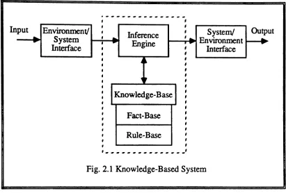
The environment/system and system/environment interfaces are very similar to the input and output units, respectively, of most modem computer systems. The
environment/system interface is responsible for extracting information from the environment, while the system/environment interface is responsible for outputing the
resultina form compatiblewith the environment, which canbea human user or a certain type of application. The physical structures of the interfaces depend on the type of application. For example, they can be the keyboard and the screen of an ordinary computer terminal, as in general applications, or a speech recognizer and a speech
2.1.2. The Knowledge Base
The knowledge base is the most important part of a knowledge-based system. This unit forms the source of the system's of intelligence. That is, it is used by the inference engine to produce intelligent results. Usually, two types of knowledge are stored in the knowledge base: declarative and procedural knowledge. Declarative knowledge consists of facts about the objects, events and situations for a given field of application, while procedural knowledge includes heuristic rules and procedures for using the declarative knowledge. The two types of knowledge may be separated or integrated depending on the method used to represent the knowledge.
The knowledge in the knowledge base is represented in a form that allows reasoning and has the capability of naming, describing, relating, organizing and constraining a set of elementary concepts. Thus, the form of knowledge representation usually depends on the type of available knowledge and on the particular requirements of the application for which the system is designed. Various forms, such as logic, semantic networks, schemata, and production rules, have been used to represent knowledge [50-53]. These forms are not mutually exclusive, however.
Logic is the oldest form of knowledge representation. Both declarative and procedural knowledge can be easily represented with logic. Propositional calculus is a typeof logic that lends itself to representing declarative knowledge with propositions or logical statements. These statements can be related by the logical relations, such asand,
25
world knowledge is limited. Anothertype of logic that is more attractive is based on predicate calculus. It uses the same concepts and rules as propositional logic. However, it has the ability of representing knowledgeinfiner detail by breaking a logical statement into components such as objects, their characteristics or some of their assenions. One weakness of logic as knowledge representation is that it does not address the issues of howtoorganize and interconnect the knowledge in the knowledge base. Therefore, other forms of knowledge representation are usedinconjunctionwithlogic in ordertostructure the knowledge base.
For instance, in semantic networks the knowledge is structured as a group of interconnected nodes. The nodes represent facts or concepts, while the interconnecting arcs represent semantic relationships between the concepts. Inference is made by traversing the arcs from one concept to the next related one. A semantic network is very useful when the knowledge can be categorized into hierarchical clusters. It also has the advantage of the inheritance property, in which children nodes inherit the properties of their parents. However, as the amount of knowledge increases, the complexity of the network becomes burdensome and the reasoning process becomes very complicated.
Scripts are very similar to frames, except that knowledge is represented with scripts, each of which describe a scenario of related events. These events always occur in conjunction with each other. They are invoked when the entry condition of the script is satisfied. This entry condition is indicatedinthe script, as well as the order of occurrence of the related events and their outcomes.
In production rules, the declarative and procedural types of knowledge are separated into a fact-base and a rule-base, respectively. The declarative knowledge is represented as propositions based on propositional logic, and the procedural knowledge is represented as a series ofif-then rules. Some of these rules pertain to the field of application, while others, called meta-rules, pertain to other production rules or even to themselves. A meta-rule guides the execution of the knowledge-based system by determining under what conditions certain rules should be appliedinpreference to others. Facts can be added or deleted from the fact base as the system executes. Facts are added whenever the assertion of a proposition is established, otherwise deleted. Production rules are the basis of most modern expert systems.
2.1.3. Tbe Inference Engine
27
The inference engine uses rules such as
Modus Ponens, Modus Tolens,
andResolution,
alongwith predicate calculus for the inference process [54]. These rules are alreadyprogrammedinto someartificial intelligencelanguage and the development tools. TheModus Ponens
rule states that ifpropositions A and (A implies B) are true, then proposition B is true. TheModus Tolens
rule says that if propositions (not B) and (Aimplies B)aretrue then (notA) is true. The
resolution
role says thatifthe propositions(A or B) and (not B or C) is true then (A or C) is true. (A or C) is called the resolvent of (A orB) and (notBorC).Forward and backward chaining are two major methods which are usedto control the inference process [53]. In forward chaining, the inference engine evaluates the predicates of each rule in the knowledge-base, then evaluates those rules which have predicates that match the consequences of the original rules. Inbackward chaining, the inference engine proceeds from the consequences of the rules to the predicates. Itfirst establishes some hypothesis, then evaluates the predicates that lead to these hypothesis. Whenever the truth of a hypothesis is established, the hypothesis is converted to a new fact that
is
added to the database.In bothforward and backward chaining,ifthetruthof a predicate can not be determined, the system seeks additional data. ITthis data is not available, thesystem
ignoresthatpredicateandproceeds the evaluation of another.searching, the knowledge tree is searched by exploring the nodes of the treein a vertical fashion, starting from the root; i.e., the search proceeds from one level to the next by successively selecting one node from the given level and then exploring one of its children, until the goal is reached. Ifthe desired goal can not bereached, the tree is traversed backward to the nearest unexplored ancestor node and the search continues forward from there inthe same fashion. Ina breadth-first search, nodes on the same level are explored until the goal nodeisreached.Ifall the nodesinone level are explored, but the goal node is not reached, then the search is continued in the next level.
The same principle as in depth-first or breadth-first searching is used in the controlled search. The only difference is that selected nodes are explored instead of exploring each node in a predetermined manner. The selection process is always based on someheuristic measure that indicates how fast a node will lead to the desired goal. Beam-search, best-first, hill-climbing, branch-and-bound, and A·, are famous examples of controlled search techniques.
2.2. Computer Animation and Image Coding
Animation can be defined as a techniquein which the illusion of movement is created by photographing a series of individual drawings onto successive frames of a film.These drawings have been previously generated such that each framein the series is an alteration of the previousframe. When the
film
is projected at a cenain rate, typically29
There are three major techniques for producing animated films: conventional animation, rotoscoping, and modeled animation [56].
2.2.1. Conventional Animation
Conventional animation is oriented towards the production of two-dimensional cartoons. The frames of the fum to be animated are hand-drawn in a tedious and time consuming process consisting of two steps. The first step is to prepare special frames called the storyboards or key frames. These frames represent the beginnings and ends of important motions, illustrate important characters' expressions, or set the tone of the animation. The second step is the in-betweening step, in which the gaps between the key framesarefilled in with a number of frames that make the motion appear to be continuous smooth.
To create one frame ofananimated film, the characters or pieces ofacharacterare hand-drawn on a clear plastic sheet of cellulose (called a eel for short). The eels are stacked together and photographed. Successive frames are then createdbychanging or moving appropriate eels of the stack and re-photographing it. For example, the facial features and expressionsmay be changed to give the impression that a character in the
filmis speaking. Also, transition and zooming techniques are used to switch from one scenetoanother ortomove into
or
a way from a scene, respectively.the key frames. For interpolation purposes, animators divide each key frame into a number of small strokes. Then they establish a correspondence between the strokes in different key frames. Therefore, the number of strokes in every two consecutive key frames, as well as, the number of points in any two corresponding strokes, must be the same. These two conditions are rarely satisfied in any animated sequence. However, a preprocessing stage can force bothconditionstobe satisfied.
There are three major interpolation techniques that can be used to produce in-between frames [56,57]. The linear interpolation technique is the simplest of all three. In this technique, the motion from one successive key frame to another is assumed to be constant, which forces the trajectory of each point in the image to bea straight line. Therefore, the location of each point in any in-between frame can beeasily determined from the positions of its corresponding two points in its two boundary key frames. Unfortunately, linear interpolation suffers from motion discontinuity at the key frames, because the motion between successive key frames is not actually constant. This discontinuity, however, can be alleviated by performing the interpolation on the basis of physical laws that drive the movement, or by using a P-eurve as an approximation to the temporal behavior of the position.
31
detailed information contained within them. The advantage of this method is that the computer can create high-quality in-between frames from consecutive key frames, which are
very
similartoeach other.A more complicated interpolation technique has been proposed by Reeves [59] to reduce motion discontinuity at the key frames, and to allow interpolation based on multiple motion paths. Themainideaistoassociate a time- and space-varying curve with selected points of an animated object. This curve then controls the trajectory and dynamics of these points in thefilm.
2.2.2. Rotoscoping
Rotoscoping is an animation technique in which the time of creating an animated film is reduced by using films of real-life actions. These actionsaretraced to produce eels which are then inked, printed andfilmed, Inso doing, it is possible to eliminate the time required to initially design the key frames and in-between frames of an animated film, as
2.2.3. Modeled Animation
Modeled animation is a recent approach in the animation industry [43,44,60,61].
In
this technique, a 3-D computer modelisfirst constructed for each character or objectto be in an animated film. These models are then manipulated either by changing some of their parameters or by applying simple linear operations such as scaling, translation, and rotationinorder to create motion. Although this approach allows considerable flexibility in defining the objects or characters and their motions, it has achieved only limited success. Modeled animation systems are awaiting improvements that would enable them to beextendible and to learn as they work. Such systems would become more powerful and intelligent with each use.2.3. Composing Pictures from Pieces of Other Pictures
Composing pictures from pieces of other pictures has long been used in applications such as animation, computer graphics, and forensics. As discussed in section 2.2, conventional animation uses characters or pieces of a character which are hand-drawn on clear plastic sheets of cellulose called eels. Several eels
may be
stacked together and photographed to create one frame of an animated film, A computer graphics system called Whatsisjace, has been developed by Gillenson and Chandrasekaran [62], to draw human faces on a graphics display. The system has pre-stored line-drawings of average human faces and facial features. The user first horizontally and vertically stretches an average facetothe desired proportions and then updates its average features by replacing them with more suitable features from the database. Special kits of facial features arealso33
memory of a witness. Photofit, Identikit, Magna/ace, Yideofit, and Minolta Montage Synthesizer[63] are examples of some commercially available kits.
Photofitand the Identikit contain a range of facial features, including eyes, noses, mouths, chins, and hair sections, that have been abstracted from monochrome photographs. Each kit has a total of a round 560 facial features. An eyewitness selects suitable facial features from the kit and assembles them into a composite image of the criminal. Featuresin the P hotofit kit are printed onto thin cards, which can be slotted together in a special frame in order to produce a composite face. Features in theIdentikit
are printed onto transparent acetate sheets and the face is created by superimposing relevant sheets.
Magna/ace is a more recently developed kit which was designed to produce a realistic composite portrait in full color. Face construction begins with a featureless face, called the clone, which is attached to a magnetic board. The individual facial features incorporate metallic backings so they can be laid smoothly and securely onto the clone, allowing a complete face to be composed feature by feature. Finally, special color overlays are placed over the composite in order to produce colors. Minor amendments can then be made to the face with cosmetic pencils and coloring materials supplied with the
kit.
The use of color in Magna/ace improves the overall quality of likeness of the composites. Magnaface enjoys a 10% overall advantage over Photofit and Identikl: [63].accessories can be transferred between a pair of composites in order to demonstrate appearance with or without disguise. No objective assessments of
Video/it's
effectiveness have been conducted, but criminals have been identified and apprehended with the aid ofYideofit images.Minolta Montage Synthesizer
is a device that optically blends features of different images into one composite image. This device has three pans: an optical blender, a closed circuit television camera, and a television monitor. The blender has four ports; one for the base input image and the other three for secondary images. Certain features are selected from the secondary images and blended with the base image. This is achieved by filtering out parts of the base image while simultaneously reflecting parts of the secondary faces. The size and brightness of each secondary image can be adjusted to obtain a good blend. The composite image then passes to the television camera and the monitor.2.4.
A General
Methodology for
Knowledge-Based
Image
Coding
35
For each class of images, there is a universal set S of primitives of which the set
P
f of primitives in any image f in the class is a subset IT Pf= (p U1) p (j2) p U, · l ' 2 'u., I
n-1).
"«
Un)}, where the superscriptii
indicates the state of the ;lh primitive P,.. then the image fcan
be representedas
the union of its primitives; i.e.,n
r
=U
p/jj)i=l
(2.1)
Ifthe universal set S is known and the subset Pj for an image f is identified from S, then the image f can be easily reconstructed from the primitives of set S, using some information about the sizes, orientations, and locations of the original primitives in f.
Since the typeof primitives that might appear in a given class of images is finite, the set Sis finite, and therefore canberepresented by a database. This database is very similar to the code book used in vector quantization, which was discussed in chapter 1. The difference is that the code book contains either one-dimensional or two-dimensional vectors, which do not represent any meaningful messages. They are simply groups of adjacent pixels, which frequently occur in the image. The database, on the other hand, contains meaningful image segments that represent the viewer's perception of the outside
world.
This databasecan
be used to code any image in the given classina way similar tothat used
invector
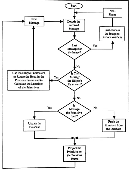
quantization.be available before coding. When the best match is found, its order in the database, along with the primitive's normalization factors and location in the original image, is coded and transmitted. IT a good match for a primitive can not be found, the primitive itself is transmitted and the databases at both the transmitter and the receiver are updated to include the new primitive.Incoding time-varying image sequences it is not necessary to extract and code all the primitives from each frame of the sequence. Instead, it is sufficient to extract and code only those primitives that have encountered significant changes, such as rotation, scaling, or deformation from one frame to the next. These primitives are then projected on the previous frame which is assumed to be stored at the receiver.
The receiver uses the transmitted information and a duplicate database to construct a faithful replica of the original image. The decoding process is similarto the idea used in
computer animation. First, each primitive is decoded from the database using its order; it is. then scaled and oriented using its normalization factors so that it assumes its original size and orientation. Finally, each primitive is projected onto its proper location in a base image, which is simple the previous frame in a time-varying image sequence, and any artifacts that mightappearin the transition regions between primitives are removed witha smoothing filter,
It is obvious that image compression is achieved in knowledge-based image
37
2.5. The Structure of the Knowledge-Based Image Codec
2.5.1. Knowledge-Based Image Coder
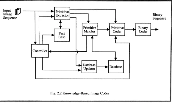
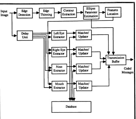
The general structure of the knowledge-based image coder is showninthe block diagram of Fig. 2.2. It consists of eight basic blocks; the primitive extractor, fact base, database, database updator, primitive matcher, primitive coder, the binary coder and the controller, which maintains the entire system.
The primitive extractor is a simple image analyzer which is used to break the image into its primitives, each of which forms a meaningful message. The primitive extractor may use a priori knowledgeto locate and extract the primitives in the image.A priori knowledge, such as the typeof image to be coded, the image formation model, the primitive location model, and the primitive motion model is stored in the fact base, which is accessible to the primitive extractor.
The primitive matcher searches the database inasequential order to find the best match
to an
extracted primitive.Ifthe best match is found, the primitive matcher passes the order of the best match to the primitive coder; however,ifthe best match is not found it passes the message (i.e., the primitive) itself to the primitive coder. The primitive coder produces two types of message based on its inputIf
the message itself is input to the primitive coder, the coder represents the primitive with a minimum number of bits by using a suitable coding strategy.H
the order of a best-match primitive is input to the primitive coder, it codes the order of the primitive and itsnormalization factors. Ineither case, the primitive coder adds overhead bits to distinguish between the two types ofThe database is a collection of many image primitives that might appear in an image in a given application. Its contents are application dependent. For instance, for head and shoulders images, the database contains pictures of various eyes, noses, mouths, hair segments and ears (see section 4.9); for facsimile purposes, it would contain alpha-numerical characters in many fonts, and basic graphics primitives.
In
any case the database is assumed to be available before coding.Input
rtr1
I:1
PrimitiveImage
Lll) ;Extractor
L
I
Sequence
iPrimitive
H
PrimitiveH
BinaryI----.
Matcher Coder Coder
I i
~...
...
t
Fact Base
•
•
Binary
Sequence
Controller
14-
)
9
+I
Database1
..I
Database_~.I Updator
L , _
Fig. 2.2 Knowledge-Based Image Coder
Yo)
2.5.2. Knowledge-Based Image Decoder
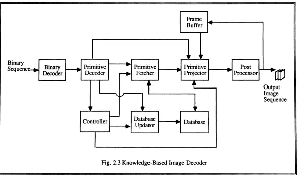
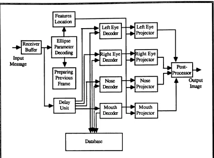
The knowledge-based image decoder operates in full synchronization with the coder, and its structure is similar to that of the coder. As depicted in Fig. 2.3, the decoder consists of nine blocks; the binary decoder, primitive decoder, primitive fetcher, primitive projector, controller, database, database updator, frame buffer, and post processor.
The binary decoder decodes the received binary message, and passes it to the primitive decoder, which in turn decides whether the primitive itself or the order of the primitive and its normalization factors was received. Ifthe primitive itself was received, then it decodes the primitive and its location in the image and passes this information to the primitive projector; otherwise, it decodes the order of the primitive and its normalization factors, and passes the order to the primitive fetcher and the normalization factors to the primitive projector.
The primitive decoder also informs the controller concerning the type of received information, whereupon the controller signals the primitive fetcher and the primitive projector to perform the required actions. For instance, if the primitive itself was received, the controller signals the primitive fetcher to do nothing, and the primitive projector to take its input from the primitive decoder. On the other hand,ifthe primitive itself was not received, the controller signals the primitive fetcher to use the order of the primitive in the database to extract the primitive from the database, and then passes the fetched primitive to the primitive projector.
41
tJrJ
ut ge uence
"
~,....
Binary
....
Primitive....
Primitive....
Primitive....
Post....
Decoder....
Decoder ~ Fetcher....
Projector....
Processor..
I
t
+
Ou~Ima
"
"./Seq ~,
"
"
-
DatabaseController ....
...
DatabaseUpdator
....
...Binary Sequenc
Fig. 2.3 Knowledge-Based Image Decoder
~
43
The database at the decoder is an exact duplicate of the one used by the coder. It is updated through the database update routine whenever the database at the transmitter is updated. Therefore, whenever a primitive itself is received, the controller informs the database updator to update the decoder's database with the received primitive.
2.5.3. General Requirement for Applying Coding Techniques
Knowledge-Based Image
It is obvious that applying the knowledge-based image coding technique to a given class of images requires the following: (1) an accurate definition of the primitives of the images in that class, (2) a fast and accurate primitive extraction algorithm, (3) the construction of a representative database of reasonable size, and (4) a way to compare primitives.
CHAPTER 3
A MODEL-BASED ALGORITHM FOR FACIAL FEATURE
EXTRACTION
3.1. Introduction
In spite of the obvious potential of face recognition to applications such as security and law-enforcement, limited success has been achieved. Most of the existing techniques are based on either verbal coding or geometrical cooing of the image, followed by a sequential or matching algorithm. Goldstein et. al. [64] used verbal cooing, which describes a picture verbally to develop an interactive face recognition system. Hannon et. al. [65-67] used geometrical coding in automatic identification of human face profiles. Each face profile in Goldstein's world was represented by a vector of seven automatically-extracted fiducial marks. These vectors were then used to compare the profile pictures. Sakai et. ale [68] and Bromley [69] developed algorithms for automatic location of the facial features in front view images. Sakai [68] used the venical and the horizontal signatures of the pixels in a slit of predetermined dimensions to determine the location of the facial features. The slit moves around the picture in search of the location of the desired feature. This location must beconsistent with the locations of other features. Whenever the algorithm detects an inconsistent location, the process is repeated
45
The location of facial features is necessary not onlyinface identification, but also in constructing composite images from parts of photographs. Gillenson and Chandrasekaran [62] developed a computer system called whatsisface,which utilizes a database of human facial features to create facial images on a CRT. Wiederhold [70] developed a computer system to simulate the Menolita Montage Synthesizer, which blends features from different pictures to produce a composite for criminal identification. In both Whatsisface and the Menolita Synthesizer, the location of the feature to be extracted or projected is determined manually. Also, determining the locations of the facial features is very necessary for our knowledge-based image coding technique.
3.2. A Model for Head and Shoulders Images
The human head is normally visualized by an artist in two ways, a cube or an egg [71,72]. The two approaches stress different prominent features of the human head that suit the drawing task. The cube shape stresses the angularity of the facial planes and the underlying bony structure of the skull. The egg shape stresses the curving quality of the skull and the fact that the facial features sit on a curve rather than on a flat surface. Neither model, however, is well suited to locating the facial features. A more mathematically appealing model is the ellipsoid. Therefore, the head of a human being can be thought of as an ellipsoid that sits on the top of the torso and is attached to it at the center by the neck.
The head movement can beclassified mainly as turning right and left or nodding up and down. Both movements are supported by the anatomical structure of the neck. The first cervical vertebra is called the atlas. It supports the skull and allows it a large turning radius. The atlas, in turn, sits on the second cervical vertebra which is called the axis. The axis is a hinge joint that allows the head to nod up and down. The remaining five cervical vertebrae are flexible and extend the possibilities of motion for the head in nearly all directions. Therefore, the head movement can beviewed as rotations a,
/3,
and6
around thex ,
y, and z. axes, respectively, which pass through the center of theellipsoid (see Fig. 3.1). The elongation and orientation of the projected ellipse are related to the head rotation angles
a,
f3
and9.
For example, in the front view position, where the anglesa
and ~are both zero, the length of the minor axis is about two thirds the length47
y
a. Normal Position
y
c.
Rotation Around Y-axis xx
y
e
b. Rotation Around X-axis
y
a
d. Rotation Around Z-axis
x
49
y
! I
2 y
Fig. 3.2 Head Model for Head and Shoulders Images
Let(CX' Cy) be the center of the ellipse that fits the head contour. Also let Ix, Iyand
e
denote the minorand
major semi-axesand
the orientation of the ellipse, respectively.51
Eyes:
Ifthe length of each eye ise
land the centers of the right and left eyes are(crex1crey)and
(clex' cley) ,respectively, then,
(3.la)
(3.1b)
crey
=
cy + e lsinO(3.1c)
Nose:
Ifthe center, length, and base width of the nose are denoted by (ncx1ncy ), n
hand nw '
respectively, then,
(32a)
!l.
n
h-2
-2-
(32b)1
n
w-S
-.:.r
(3.2c)Mouth:
Ifthe center, height and width of the mouth barrel are denoted by (mcx' mcy),mhand mw ' respectively, then,
21
mcx= Cx - TSinO
~
mc
y=
c
y+
3cose
(3.3a)
(3.3b)
(3.3c)
Equations (1)-(3) are used in the facial feature extraction algorithm to estimate the location of the facial features.
The parameters of the ellipse are estimated by fitting the head contour points with the ellipse function,
2 2
53
It is easy to show that the center(cx'cy)of this ellipse is given by
be - cd
c
-x - 2(ac-b2)
bd - ae
c
-y - 2(ac - b2)
and the orientation () is given by
1
-1(
b )(}=-tan
-2 a - c
The major and minor semi-axes,lx,andIy,are given by
(35a)
(35b)
(3.5e)
(3.5d)
(3.5e)
n
~ 2 2
S= ~(dti)
+
(L1Yi);=1
(3.6)
where dti and AYiare the
x
andYdeviations of the head contour point (Xi, Yi) from the ellipse contour. An iterative solution for this problem using the Lagrange multiplier method is showninthe Appendix. The algorithm starts by guessing the parameters of the ellipse. This initial guess can be some pre-defined values or the values of the parameters of the ellipse that fits five head contour points which are almost equidistant from each other. The algorithm then updates the initial guess by solving a set of linear equations for the deviation from the initial guess. The process continues until the deviation no significant improvement in the estimated parameters can be obtained with further iterations.3.3. Facial Features Extraction Algorithm
55
Furthermore, thin edges result in better performance from the fitting algorithm. Hence, after thresholding the enhanced image, a thinning operator is applied to produce the thinned edges. The outer most head contours are extracted from the thinned image, and
Convolvewith Sobel Edge
Operator
Threshold the Imageto Produce
Binary Edges
Use Chen et.ale Algorithm to Thin the Edges
Scan Image BottomtoTop. LefttoRight Until Non-Zero
Pixel.Make It Current Pixel
57
EraseCurrentPixel from InputFile Yes
Make Pixel Current Pixel and Save Itin OutputFile
Yes
Make Non-Zero Pixel Current Pixel. Save Current Pixel and All Pixels on a Straigth Line
Between This Pixel and Previous Pixel in
Output file
Fig. 3.3b Flowchart for Head ContourExtraction
Initialize Ellipse's Parameters
Compute Lagrange's Multipliers
Compute parameters' deviation
Update Parameters
Estimate Features' Locations
Compute Signature AroundMouth
andNose
Adjust Mouth and NoseLocation