VLSI Design of Syndrome Computation Block
for RS(255,239) Code
Pranali D. Surkar1, Swapnil D. Ninawe2
Assistant Professor, Dept. of Electronics and Communication Engineering, PIET, Nagpur, Maharashtra, India1
Assistant Professor, Dept. of Electronics and Communication Engineering, PIET, Nagpur, Maharashtra, India2
ABSTRACT: This paper presents a design of syndrome computation block for Reed-Solomon decoder for RS (255, 239) code. For calculating the syndromes, three-parallel processing has been used. Parallelizing allow inputs to be received at very high rates and outputs to be delivered at correspondingly high rates with minimum delay. RS (255, 239) code consists of 255 symbols which are multiple of 3. Hence three symbols are inputted parallely in syndrome computation block. Complete process required 85 clock cycles to compute one syndrome coefficient. The proposed three-parallel RS decoder architecture is modeled in Verilog HDL and simulated to verify its functionality. This process can be adapted in the FEC devices.
KEYWORDS:Galois Field, Reed-Solomon codes, syndrome, three-parallel.
I. INTRODUCTION
Reed-Solomon (RS) coding is one of the most powerful and standardized technique for error and erasure correction [1]. Owing to its excellent capability for correcting burst errors, these codes have been widely used in a variety of communication systems such as storage devices (CD, DVD, etc), space communication links, wireless system as well as networking communications. Adapting pipeline technique in the conventional syndrome block is crucial but due to its feedback loop, applying pipeline technique to the syndrome block will make its required clock
cycles double [2]. For two parallel syndrome computation over GF (28) we have to add one dummy zero input where
they need n/2 clock cycles to finish [3].
In this paper, we present the three-parallel syndrome computation block for RS decoder. For this, we consider RS (255, 239) code. Section II describes the Galois field arithmetic which includes Galois field addition and multiplication. And also shows the representation of field elements and its binary form. Section III shows the calculations of syndrome and in section IV, architecture of three-parallel syndrome computation (SC) block for RS decoder has discussed.
II. RELATED WORK
A Galois field (also called finite field) is a mathematical structure which plays a crucial role in the theory of RS codes and the finite field arithmetic operations are the fundamental building blocks for the RS decoder [5]. The Reed-Solomon code is defined in the Galois field which contains a finite set of numbers where any arithmetic operations on elements of that set will result in an element belonging to the same set [6]. Every element, except zero can be expressed
as a power of a primitive element, α of the field. RS (255, 239) code belongs to GF (28). Therefore the primitive polynomial over GF (28) will be x8+x4+x3+x2+1.This is a polynomial of degree m which is irreducible that is, a
polynomial with no factors. Table. 1 represents the field elements and its binary form over GF (28).
A. Galois Field Adder
(2
8)
B. Galois Field Multiplier (28)
Multiplication is more complex than addition as the addition is only XOR operation. But multiplication is different and depends on Galois field structure and its primitive polynomial and the type of basis coefficients.
Let A and B be the multiplier and multiplicand over GF (28), respectively. A and B can be describe as equation 1.
A = + +∙∙∙∙∙∙+ = ∑ (1)
B = + +∙∙∙∙∙∙+ = ∑ (2)
Table.1 Field elements and its binary form over GF (28).
Then their product Z can be described as equation (3).
Z = A∙B = ∙ ∑ =∑ ( ) (3)
The GF (28) multiplier is implemented as equation (4).
= + + + + + ( + ) + ( + + ) + ( + + + ) = + + + + + + ( + ) + ( + + ) = + ( + ) + ( + ) + ( + ) + ( + ) + ( + + ) +( + + + ) + ( + + + ) Field elements in powers of α
Field elements in binary form Decimal Form
α0 α1 α2 α3 α4 α5 α6 α7
0 0 0 0 0 0 0 0 0 0
α0
1 0 0 0 0 0 0 0 1
α1
0 1 0 0 0 0 0 0 2
α2
0 0 1 0 0 0 0 0 4
α3 0 0 0 1 0 0 0 0 8
α4 0 0 0 0 1 0 0 0 16
α5
0 0 0 0 0 1 0 0 32
α6
0 0 0 0 0 0 1 0 64
α7
0 0 0 0 0 0 0 1 128
α8
1 0 1 1 1 0 0 0 29
α9
0 1 0 1 1 1 0 0 58
. ∙ ∙ ∙ ∙ ∙ ∙ ∙ .
. ∙ ∙ ∙ ∙ ∙ ∙ ∙ ∙ .
. ∙ ∙ ∙ ∙ ∙ ∙ ∙ .
= + ( + ) + ( + + ) + ( + + ) + ( + + ) + ( + + + ) +
( + + + ) + ( + + + )
= + ( + ) + ( + + ) + ( + + + ) + ( + + + )
+ ( + + ) + ( + + ) + ( + + + )
= + + ( + ) + ( + + ) + ( + + + ) + ( + + + ) +
( + + ) + ( + + )
= + + + ( + ) + ( + + ) + ( + + + ) + ( + + +
) + ( + + )
= + + + + ( + ) + ( + + ) + ( + + + ) + ( + + +
)
(4)
Figure 1 : Simulation result of Galois field multiplier (28)
Fig.1 shows the simulation result of Galois Field Multiplier (28) which gives the 8 bit output after giving 8 bit inputs.
III. SYNDROME CALCULATIONS
Syndrome is actually a set of symptoms or characteristics indicating the existence of undesirable condition or problem. The first step in RS decoder is to check if there is any error in the codeword or not. This is done using syndrome computation block by calculating syndromes coefficients. Here the syndrome is in the form of bit error. An
(n, k) RS code has k message symbols and n coded symbols, where code symbol belongs to GF (2m). The (n, k) RS
code has a minimum distance of d. From an RS code, an error can be corrected by finding out the error location and error value, where an erasure is defined as an error with a known error location. RS code is specified as RS (n, k) with m-bit symbols. RS (n, k) codes on m-bit symbols exist for all n and k for which 0 < n < k ≤ 2m-1. For this project, (255, 239) RS code [1] is targeted for syndrome computation block over the Galois field (28). Therefore the primitive
polynomial over GF (28) will be x8+x4+x3+x2+1. From the primitive polynomial, binary elements of the polynomial are
obtained. For this, n = 255 is the total no. of code symbols after encoding called codeword.
k = 239 is the no. of data symbols to be encoded. m = 8 is no. of bits
t = (n - k) / 2 is the no. of symbols that can be corrected with this code n - k = 16 syndromes to calculate
Syndrome computation block calculates all the syndromes Si (0 ≤ i ≤ 15) by putting the roots of generator polynomial
where,
R(x) = r254x254 + r253x253 +……. r1x + r0 (5)
G(x) = (x-α0) (x-α1) ……. (x-α14) (x-α15) (6)
Si = R(αi) = r254(αi) 254 + r253(αi) 253 +……. r1(αi) + r0 (7)
If there is no error in the codeword, all the syndromes computed are zero. Non zero syndromes imply an error in the codeword and these are then passed to subsequent blocks for computing the error value and error location.
IV. THREE-PARALLEL SC BLOCK
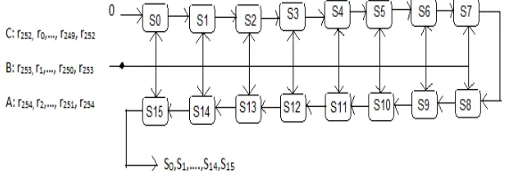
As shown in fig. 2 [1], three parallel syndrome computation block for RS (255, 239) code is given. The received codeword consisting of 255 symbols which are multiple of 3, hence in syndrome computation block processing, reduction of clock cycles is targeted.
The received codeword from RS encoder which is to be given as input to the RS decoder is first stored in shift register and then inputted in parallel manner to the syndrome computation block. At the first clock, the received codeword( r254, r253,r252 ) are inputted parallel. As three symbols inputted parallel, first symbol r252 is going directly to the adder. Second symbolr253 is first multiplied by αi then added with r252. Third symbol r254 is multiplied by (αi)2 and then added withr253 andr252. So the output of adder becomes r254(αi)2+ r253(αi)1 + r252 which get stored in the latch (1). At the
next clock cycle, the output of latch (1) is multiplied by (αi)3, as three symbols are inputted and then added withr251(αi)2+ r250(αi)1 + r249. This iterative process will be performed and syndromes Si is stored in latch (1). Multiplexer selection (3) and (4) becomes 1 after all the clock cycle performed by one syndrome calculation, to shift syndromes Si to the latch (2) and to compute new received codeword.
Figure.2 : Three parallel syndrome computation block
Three-parallel syndrome computation has to be done by equation (8).
Si = R(αi) =((…(r254(αi)2+ r253(αi)1 + r252) (αi)3 +r251(αi)2+ r250(αi)1 + r249) (αi)3+ ….) (αi)3 + r2(αi)2+ r1(αi)1 + r0 ) (8)
Therefore the syndromes S0,S1,……,S15 are outputted serially to the KES block.
The input patterns of the three-parallel syndrome computation cell are shown in Table 2. The whole computations will take 85 clock cycles as it is a three-parallel processing and we have total 255 symbols which are inputted in the group of 3.
Table 2. Input patterns of the three-parallel syndrome computation cell
Clock 1st 2nd …… 85th 1th
Input A r254 r251 …… r2 r254
Input B r253 r250 …… r1 r253
Input C r252 r249 …… r0 r252
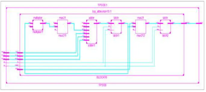
Fig. 4 shows the RTL schematic of SC block. And table 3 describes the complete processing of first SC block along with the inputs symbols and the clock cycles required for the process. Also output is shown.
Figure 4: Technology schematic of SC block
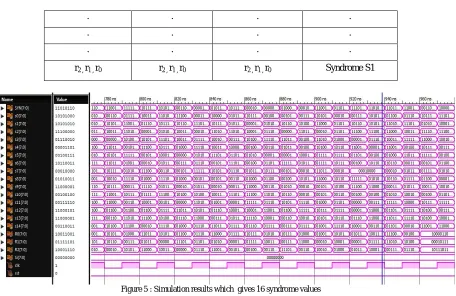
The iterative process will continued till all 255 symbols inputted parallel in the group of three as shown in table 3. Final output S1 is added with the next SC block and generates S2. Likewise the process continues till 16 syndrome values are computed. Fig. 5 shows the output waveform.
Table 3: Processing of SC block
Step 1 Input symbols Step 2 Step 3 Output
r254, r253, r252 r254*α2, r253*α1, r252 output of step 2 * α3 add to next 3 symbols
r251, r250, r249 r251*α2, r250*α1, r249 output of step 2 * α3 add to next 3 symbols
. . . .
. . . .
. . . .
r2 , r1 , r0 r2 , r1 , r0 r2 , r1 , r0 Syndrome S1
Figure 5 : Simulation results which gives 16 syndrome values
V. RESULT AND CONCLUSION
The proposed syndrome computation block calculates the syndrome coefficients. As three symbols are inputted in parallel, the required clock cycles to compute each syndrome are reduced. Parallelizing allow inputs to be received at very high rates and outputs to be delivered at correspondingly high rates with minimum delay. As a result of this, speed of RS decoder will increase. The proposed three-parallel syndrome computation block has modeled in Verilog HDL and simulated to verify its functionality. For complexity consideration, constant-variable finite field multiplier is used to implement the syndrome computation block as it requires much fewer gates. The whole computation required 85 clock cycles. Table 4 shows results using Verilog HDL
Table 4.Results using Verilog HDL
VI. REFERENCES
[1] Chang - Seok Choi and Hanho Lee, “High- Speed Low-Complexity Three parallel Reed-Solomon Decoder for 6 Gbps mm Wave WPAN Systems,” IEEE Conference Publications, Circuit Theory and Design, pp.515-518, 2009.
Sr. No. Parameters Three-Parallel SC block
1 Clock Cycles 85
2 Delay 7.878ns
3 No. of gates 992
[2] L. Song, M-L. Yu and M. S. Shaffer, “10 and 40- Gb/s Forward Error Correction Devices For Optical Communications ,” IEEE Journal of
Solid-State Circuits, vol. 37, no. 11, pp. 1565-1573, Nov. 2002.
[3] S. Lee, C-S. Choi and Hanho Lee, “Two-parallel Reed-Solomon base FEC Architecture for Optical Communications,” IEICE Electronic
Express, vol. 5, no.10, pp. 374-380, May 2008.
[4] Hanho Lee, “High-Speed VLSI Architecture for Parallel Reed-Solomon Decoder,” IEEE Trans. on VLSI Systems, vol. 11, no.2 pp. 288-294, April 2003
[5] Jeong-In Park, Kihoon Lee, Chang-Seok Choi, and Hanho Lee, “High-Speed Low-Complexity Reed-Solomon Decoder using Pipelined Berlekamp-Massey Algorithm and Its Folded Architecture,” Journal of Semiconductor Technology and Science, vol.10, no.3,september,2010 [6] Jae Do Lee and MyungHoonSunwoo, “Four Channel Three-Parallel Reed Solomon Decoder using S-DCME Algorithm for Optical
Communications,” IEEE, 2010.
[7] S. Lee and Hanho Lee, “A High-Speed Pipelined Degree- Computationless Modified Euclidean Algorithm Architecture for Reed-Solomon Decoders”, IEICE Transactions on fundamentals of Electronics,Communications and Computer Sciences, vol. E91-A no.3, pp.830-835,March2008.