Design and Fabrication of Electrically
Powered Exoskeleton for Work Augmentation
Deepakkumar S1, Devanand S S2, Prakash Narayanan A 3
U.G. Student, Department of Mechanical Engineering, PSG College of Technology, Peelamedu, Coimbatore, India1
U.G. Student, Department of Mechanical Engineering, PSG College of Technology, Peelamedu, Coimbatore, India2
U.G. Student, Department of Mechanical Engineering, PSG College of Technology, Peelamedu, Coimbatore, India3
ABSTRACT: Improving the strength, speed, and endurance through wearable assistive devices has been the dream of humans for several decades. Several technologies have been developed towards that dream.An important goal of the field of robot-assisted movement training is to develop a light and powerful robotic-arm exoskeleton. Many exoskeleton designs exist but none have matched or exceeded the capabilities of the human arm in terms of inertia, strength, force-control ability, and range of motion.Robotic exoskeleton is getting important to human in many aspects such as power assist, muscle training, regain motor function and rehabilitation. The research and development towards these functions are expected to be combined and integrated with the human intelligent and machine power, eventually becoming another generation of robot which will enhance the machine intelligent and human power. The goal of this project is to design and fabricate a mechanical exoskeleton for work augmentation. The exoskeleton must be made portable and as light as possible in order to provide comfort for the person. The type of exoskeleton chosen is an upper extremity exoskeleton.
KEYWORDS: Upper extremity exoskeleton, work augmentation, upper extremity, exoskeleton suit.
I. INTRODUCTION
Robotic exoskeleton is getting important to human in many aspects such as power assist, muscle training, regain motor function and rehabilitation. The exoskeleton is an electromechanical structure worn by operator and matching the shape and functions of human body. It augments the ability of human limb and/or to treat muscles, joints, or skeletal parts which are weak, ineffective or injured because of a disease or a neurological condition. Moreover, it merges the machine power and the human intelligence in order to enhance the intelligence of the machine and to power the operator. The first powered exoskeleton was an exoskeleton suit co-developed by General Electric and the US Military named Hardiman used to amplify the strength of soldier in order to carry heavy weapons, tools and equipment. The exoskeleton works mechanically in parallel with human body and can be actuated passively and or actively. One of the proposed main uses for an exoskeleton would be enabling a soldier to carry heavy objects (80–300 kg) while running or climbing stairs. Not only could a soldier potentially carry more weight, he could presumably wield heavier armor and weapons. Another area of application could be medical care, nursing in particular. Exoskeletons could also be applied in the area of rehabilitation of stroke or Spinal cord injury patients. An exoskeleton could reduce the number of therapists needed by allowing even the most impaired patient to be trained by one therapist, whereas several are currently needed. The exoskeleton dealt in our project is specialized for lifting weights.
load carrying capacity in the ratio of 1:2. The pneumatic systems also gave the advantage of holding the load for sufficiently longer duration. They have explained the working of fluidic muscles and demonstrated experiments to show its working. In [3],Alex Ansari, Christopher G. Atkeson, Howie Choset, and Matthew Travers in their paper reviewed the existing exoskeleton technologies. They explained about BLEEX a lower extremity exoskeleton. It uses hydraulic actuation and provides high power to weight ratio. Another exoskeleton model is HAL which is full body exoskeleton. It is rehabilitation type of exoskeleton. The above mentioned paper also listed other types of exoskeleton like XoR, Body extendor, HLEE etc.
The work in this paper is divided in two stages. 1) Design of exoskeleton 2) Fabricating the exoskeleton. The exoskeleton design is divided into four divisions namely 1) Hand link design 2) Back frame design 3) Actuator selection and design 4) Electrical circuit design. The fabrication of exoskeleton was done based on the design of the handlinkandbackframe.Material selected was cold rolled structural steel for the links and the frame.
Paper is organized as follows. Section II describes the design calculations made for the hand link,back frame, actuators and the electrical circuit. After the calculations being performed, modelling and structural analysis of the exoskeleton is given in Section III. Section IV presents the fabrication process carried out and the testing of the exoskeleton.
II. DESIGN CALCULATIONS
The four divisions in the design are summarized as follows.
1. The hand linkages were attached to the back frame and were located on either side of the body. They acted as a first class lever with the pivot at the centre.The load and the actuating force wereon either ends of the link.The lengths of the links and the forces acting on them are shown in the fig.1 (a).The law of moments was applied to obtain the force that the actuator must provide in order to lift the weight. The force that balances the load was found to be 530N, hence in order to lift the load a force greater than 530N must be applied.
2. The back frame consisted of two vertical structures with two cross links in order to set them apart.The hand linkages were supported on either side at the top through L links projecting forward. They were welded to the back frame. Similar L links projecting backwards were used to attach the actuator.The actuators were fixed rigidly at the end to the back frame. Hence the stress induced in the L link and the strength of the welds must to be determined. The material used was cold rolled steel. The axial stress, maximum normal stress were calculated for each link and they were within the yield strength of the material chosen.
3. The primary purpose of the actuator is to produce the required force needed to lift the load. The method of actuation can vary but the basic principle is same. It is, the actuator must multiply the torque produced by the motor and deliver it in the other end in the form of either a force or torque. Five different methodsof actuation like chain drive, pneumatic actuators, worm and worm wheel, Non captive type linear actuator and reverse parallel linear actuators were considered and design calculations were performed for each type.The electrical actuators were selected due to their superiority over actuating mechanisms in terms of compact size, load capacity and weight.Reverse parallel linear actuator as shown in fig. 1(b) with an extension of 300 mm was selected.
Fig. 1.Design Calculations (a) Forces acting on the actuator (b) Reverse parallel linear actuator (c) Electrical circuit design
III.MODELLING AND STRUCTURAL ANALYSIS
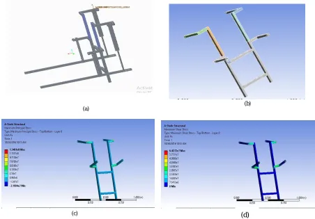
According to the calculated dimensions, the individual model of each component were modelled and then assembled in PTC Creo Parametric software as shown in the fig.2(a).The analysis was done in the back frame by transmitting all the forces to the back frame. It was imported in to design modeller of ANSYS work bench as shown in fig.2(b).The material used was cold rolled mild steel with a tensile strength of 460 MPa.A coarse mesh was done and the boundary conditions were 780 N at the end of forward projecting L links and 530 N at the end of backward projecting L links. The side of the frame were fixed.The maximum principal stress and maximum shear stress was found to be 134MPaand 64.2 MPa which are shown in the fig.2(c) & (d) respectively.
(a)
(a) (b)
(c)
The fabrication of exoskeleton was done based on the design calculations done for the hand link and backframe. The electrical systems was constructed as per the circuit. The following materials were procured: 1) Square pipes 2) Fasteners 3) Rod end bearing 4) Linear actuators 5) Batteries. The weight of the exoskeleton should be as low as possible to provide comfort to the person using it, hence holes of ø10mm were drilled at a pitch of 10mm in the hand link as shown in fig.3(a). The holes were marked, punched and drilled using vertical drilling machine. Totally 476 holes were drilled in the structure. The weight reduction due to these holes was 0.85kg.In order to allow the fore arm link to revolute about the pivot point, slots of size 50 x 20 was made on both top and bottom surfaces of bottom arm link. To provide the sliding motion of the pin and the bottom end of the actuator, a slot was machine don the sides of the bottom arm link. The machining was done on DRO milling machine. The ends of the hand link was cut open to allow unrestricted motion of the actuator as shown in fig.3(b).
The square pipe was cut into two lengths of 850 mm to make the vertical structures of the back frame. In order to provide comfort to the person, the cross linkages made out of square pipe was bent to match the shape of the body as shown in fig. 3(c).First, two notches were created at a distance of 100 mm from either end and then the pipe was fixed on the bench vice and bent to the required amount. These two cross linkages were positioned such that they rested behind the shoulder and the hip. They were welded to the vertical structures and the notches were also filled with weldments.
In order to mount the hand links and the actuators, four L links were made, and were welded to the back frame, two projecting forward for hand links and two projecting backward for actuator. Finally holes were drilled on the L links. The holes drilled were of ø8mm on the side of the actuator and of ø10mm on the side of the hand link. The whole assembly of back frame, hand links and actuators were mounted on the human body by means of shoulder straps. One end of the strap was connected to cross link and the other adjustable end was connected to the bottom of the back frame. To improve the comfort of wearing the exoskeleton, back straps were also provided on the back side attached to the back frame. The final assembled exoskeleton was shown in the fig.3(d).
(b) (a)
Fig. 3 (a) Holes drilled for weight reduction(b) Slots for forearm link (c) Backframe with four L-links (d) Fabricated component
The loads of 5kg and 10kg weights were used for testing, which were suspended by means of wires. The end effector was made using two M10 bolts of 100mm length. The two arms of the exoskeleton were loaded equally. First each arm was loaded with 5kg and tested. The time of lift was 21s and time of descent was also 21s.The loading condition was increased to 10kg on each arms (Total of 20kg). Similar time of lifts was obtained.
V. RESULTS AND DISCUSSIONS
From the testing, it was found an adult would be able to lift up to 40kg using the upper extremity exoskeleton. The overall weight of exoskeleton frame with actuators was 8.5kg and was comfortable to wear. This is because of the weight reduction by drilling 10mm holes along the arm links and the back straps. The power source for the actuators were obtained from lead acid batteries. If it is a lithium polymer battery (more compact and weightless but costlier) it can be mounted in the exoskeleton itself. The time of lift and descent was unaltered by the load carried and was dependent on the voltage of the input as shown in Table 1.
Table 1. Time of lift and time of descent for different loads and Voltage.
S.No. Load on Right arm (kg)
Load on Left arm (kg)
Total load (kg)
Voltage (V)
Time of Lift (s)
Time of descent (s)
1 5 5 10 24 21 21
2 10 10 20 24 21 21
3 5 5 10 18 34 34
4 10 10 20 18 34 34
The material for links used were cold rolled steel which has a density of 7800kg/m3. Using a material with better strength to weight ratio can reduce the load due to exoskeleton on the human.The ILO suggests that maximum weight that can be carried by an average male human being as 50kg. Such a weight can be carried only in overhead position or on the back while bending. This can cause discomfort. Thus the upper extremity exoskeleton enabled lifting such an amount of load with the backbone upright.
Using exoskeleton, the load was transferred to the back bone and shoulder hence relieving the stress in hands. This means that 20 kg can be comfortably carried by exoskeleton, while remaining load of 5 kg can be carried by hand. Without exoskeleton an adult cannot carry comfortably 15kg using hands for over 5 minutes. Whereas using exoskeleton it was possible to carry 20 kg for over 10-15minutes. Thus the increase in load carrying capacity due to exoskeleton is 33%. (This value will differ from one person to another).
REFERENCES
[1] Kwok- Hong Chay, Jer-Vui Lee, Yea- Datchauah and Yu- Zheng Chong “ Upper extremity robotics exoskeleton : Application,structure and actuation” , International journal of Biomedical Engineering and Science (IJBES), Vol. 1, No. 1, April.pp. 35-45.2014
[2] Abdulla Almomani, Faisal Miqdadi, Mustafa Hasaanin, Mustafa Samy and Mohammed Awadallah. “The 1st pneumatic fluidic muscles based exoskeleton suit in the U.A.E., IEEE.pp. 1-6.
[3] Alex Ansari, Christopher G. Atkeson, Howie Choset, and Matthew Travers. “A Survey of Current Exoskeletons and Their Control Architectures and Algorithms”. Carnegie Mellon University, October 1, 2015.
[4] Yamamoto K., Hyodo K., Ishii M., and MatsuoT., “Development of power assisting suit for assisting nurse labor”, JSME International Journal Series C, Vol. 45, no. 3, pp. 703-711. 2002.
[5] Yupeng, R., Hyung-SoonP., and Li-QunZ., “Developing a whole-arm exoskeleton robot with hand opening and closing mechanism for upper stroke rehabilitation," IEEE International Conference on Rehabilitation Robotics. Kyoto, Japan.2009.
[6] Mohammed S,AmiratY,RifaiH. “Lower-limb movement assistance through wearable robots: state of the art and challenges.” AdvRobot 26(1– 2):pp.1–22.2012.
[7] Tingfang Yan, Marco Cempini, Calogero Maria Oddo, Nicola Vitiello “Review of assistive strategies in powered lower-limb orthoses and exoskeletons”.Robotics and Autonomous Systems 64. pp. 120–136.2015