ISSN(Online) : 2319-8753 ISSN (Print) : 2347-6710
I
nternational
J
ournal of
I
nnovative
R
esearch in
S
cience,
E
ngineering and
T
echnology
(An ISO 3297: 2007 Certified Organization)
Vol. 5, Issue 9, September 2016
Simulation Modal of DVB-S2 using without
and with Filter
Prakash Patel1, Dr. Snehlata Kothari2, Dr. Dipesh Kamdar3
Research Scholar, Department of Electronics and Communication Engineering, Pacific University, Udaipur, Rajasthan,
India1
Professor, Co-Ordinator Pacific University, Udaipur, Rajasthan, India2
Associate Professor, Department of Electronics and Communication Engineering, V.V.P Engineering College, Rajkot,
Gujarat, India 3
ABSTRACT: This paper presents simulation model of the DVB-S2 Using Filter implemented in Simulink Matlab. The model provides simulation of the DVB-S2 system parameters in AWGN (Additive White Gaussian Noise) channel. The aim of this model is to propose DVB-S2 parameters using without and with filter in different propagation conditions. The simulation offers modulation scheme QPSK (Quadrature Phase Shift Keying). During the simulation, BER (bit error rate) versus SNR are calculated and the constellation diagram is observed. Simulation results, obtained by using consolation diagram without and with filter, also comparison between two so, that QPSK modulation Using filter is more robust compared to without
KEYWORDS: QPSK, DVB-S2, AWGN, Filter
I. INTRODUCTION
DVB-S2 is built on the DVB-S system, with certain upgrades. It was developed by DVB Project in 2003 and is based on three concepts: the best transfer characteristic nearing the Shannon limit, complete flexibility, and an acceptable receiver complexity [2].
The DVB-S system uses QPSK (Quadrature Phase Shift Keying) modulation in conjunction with internal RS (Reed- Solomon) convolution coding and FEC (forward error correction). The DVB-S2 system uses other modulation schemes in addition to QPSK. For broadcasting over non- linear satellite transponders, QPSK and 8-PSK (8 Phase Shift Keying) are used, while 16-APSK (16 Amplitude and phase- shift keying) and 32-APSK (32 Amplitude and phase-shift keying) are utilized when a highly linear transponder and a better C/N (carrier-to-noise) ratio are available.
Error correction used in DVB-S2 utilizes BCH (Bose- Chaudhuri-Hocquenghem) with LDPC (Low Density Parity Check) internal coding, with its code ratio being 1/4, 1/3, 2/5,1/2, 3/5, 2/3, 3/4, 4/5, 5/6, 8/9, or 9/10.[7] In very unfavourable conditions with SNR ratio lower than 0 dB - 1/4, 1/3, or 2/5 code ratios with QPSK modulation scheme are mostly used. Other code ratio 1/2, 3/5, 2/3, 3/4, 4/5, 5/6, 8/9, or 9/10 SNR more than 0dB.[8]
Besides CCM (Constant Coding and Modulation) with fixed modulation schemes, DVB-S2 system also uses ACM (Adaptive Coding and Modulation) techniques for transfer characteristics optimization[1]. FEC and modulation scheme still remain unchanged within a single frame, but ACM usage allows changing between different frames. FEC utilizes bit interleaving for 8-PSK, 16-APSK, and 32-APSK modulation schemes in order to prevent error bursts and the subsequent data loss.
ISSN(Online) : 2319-8753 ISSN (Print) : 2347-6710
I
nternational
J
ournal of
I
nnovative
R
esearch in
S
cience,
E
ngineering and
T
echnology
(An ISO 3297: 2007 Certified Organization)
Vol. 5, Issue 9, September 2016
II.RELATEDWORK
The DVB-S2 Using Without filters simulation shown in Fig. 1. And With filter simulation Shown in Fig.2 its main components are the following signal processing blocks:
BBFRAME Buffering block - used to prepare BB (Base Bend) frames to serve as input frames for the BCH encoder. All frames are arranged according to the BCH encoder input data size. Input data frames (188 byte or 1504 bit) are stacked up to the size determined by the number of information bits transferred within one BCH codeword. Where necessary, the input BCH frame is stuffed with zeroes to ensure the fixed size of all encoder input frames.
Figure: 1 DVB-S2 Using Without filter simulation Modal Figure: 2 DVB-S2 Using With filter simulation modal
BCH encoder block -performs forward error correction encoding. BB frames prepared in the BBFRAME Buffering block are processed by the BCH encoder. BCH encoder adds redundant bits that are used for correction of errors caused by transmission over error-prone wireless channel.[4][10]
LDPC encoder block- performs internal error correction encoding based on parity bit calculation and their insertion into the information bit sequence. In this simulation the output FEC frame (after BCH and LDPC encoding) will always retain a fixed size of 64800 bits. LDPC encoding is the last block of the error correction processing.[5][6]
Block Interleaver - performs interleaving of bits from received FEC frames in order to distribute energy and reduce burst errors. In the simulation, bit interleaving is performed by writing the frame data into columns and reading three consecutive columns as rows.
Modulator block – performs signal modulation. The simulation offers modulation scheme options QPSK with 1 / 2 code ratio[15].
Filter Block- we implemented a filter both sides transmitter and receiver to reduce the effect of cross talk and channel noise[6]. The filter will regenerate the pulse amplitude based on the transfer function. To improvement in the performance of DVB-S2 with filter system (Figure: 2 DVB-S2 Using With filter simulation modal.
The Sim link-designed simulation covers the basic mechanisms of signal processing and transmission during signal broadcast in the DVB-S2 system. Input data packet and processed with error correction encoding, modulation [12], wireless channel transmission, demodulation, error correction decoding and Filter.
ISSN(Online) : 2319-8753 ISSN (Print) : 2347-6710
I
nternational
J
ournal of
I
nnovative
R
esearch in
S
cience,
E
ngineering and
T
echnology
(An ISO 3297: 2007 Certified Organization)
Vol. 5, Issue 9, September 2016
to the DVB-S2 architecture standardized by AWGN channel block simulates the wireless channel which adds white Gaussian noise to the transmitted signal [11 ]. It is assumed that the transmitter-receiver synchronization is ideal[13]. Only normal 64800 bit FEC frames.[9]
Using the Mat lab-designed model, a SNR value required to transmit data over the wireless channel without affecting the quality of the received packet was determined. This value was used as a starting point and a minimal value required to transmit the Packet without loss was found.[14]
.
III.EXPERIMENTALRESULTS
DVB-S2 Using Without filter simulation Modal Shown in the figure.1, the effect of channel behaviour in terms of SNR over transmitted data can be observed. It can be observed that as the SNR of AWGN channel decreases and BER of system increases proportionally. It also shows that at very low SNR the symbols are very difficult to recognize. Input random Data generator, Its Data has been transmitted through this model. The measurement of working in terms of numerical values can be observed by considering the result of BER calculator. Shown in figure: 3 BER verses SNR for QPSK
.
SNR
-11 -10 -9 -8 -7 -6 -5 -4 -3 -2 -1 0 1 2
B
E
R
10-4 10-3 10-2 10-1 100
Without Filter
Figure: 3 BER verses SNR for QPSK for DVB-S2 without filter
The Constellation Diagram of the QPSK Transmitter is presented below on the receiver part; Shown in figure: 4 Scatter Plot of Receiver SNR= 0 dB without Filter for QPSK
ISSN(Online): 2319-8753 ISSN (Print): 2347-6710
I
nternational
J
ournal of
I
nnovative
R
esearch in
S
cience,
E
ngineering and
T
echnology
(An ISO 3297: 2007 Certified Organization)
Vol. 5, Issue 9, September 2016
DVB-S2 Using With filter simulation Modal Shown in the Figure 2. The below figure: 5 Represent graph between BER verses SNR. From the graph it can be observed that as the SNR of AWGN channel decreases BER o f syst em increases proportionally
.
SNR
-11 -10 -9 -8 -7 -6 -5 -4 -3 -2 -1 0 1 2
B
E
R
10-4 10-3 10-2 10-1 100
With Filter
Figure: 5 BER verses SNR for QPSK for DVB-S2 with Filter
The Constellation Diagram of the QPSK Transmitter is presented below on the receiver part; Shown in figure: 6 Scatter Plot of Receiver SNR= 0 dB without Filter for QPSK
Figure: 6 Scatter Plot of Receiver( SNR= 0 dB) without Filter for QPSK
ISSN(Online): 2319-8753 ISSN (Print): 2347-6710
I
nternational
J
ournal of
I
nnovative
R
esearch in
S
cience,
E
ngineering and
T
echnology
(An ISO 3297: 2007 Certified Organization)
Vol. 5, Issue 9, September 2016
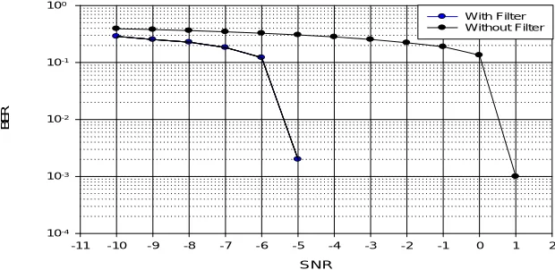
Scatter Plot of DVB-S2 Receiver (SNR=0 dB) without Filter for QPSK and Figure 6 Scatter Plot of DVB-S2 Receiver (SNR= 0dB)
SNR
-11 -10 -9 -8 -7 -6 -5 -4 -3 -2 -1 0 1 2
B
E
R
10-4 10-3 10-2 10-1 100
With Filter Without Filter
Figure 7 BER verses SNR for QPSK for DVB-S2 without and with filter
IV.CONCLUSION
In this paper the basic technical features and principles of the DVB-S2 system are described. Simulation of DVB-S2 transmission through AWGN channel was done by using modulations QPSK Without and with filter. Results of simulation showed that QPSK modulation with filter is more robust to noise without filter DVB-S2 system.
REFERENCES
[1] Bonnaud, A., Feltrin, E., & Barbiero, L. (2014). DVB-S2 Extension: End-to-End Impact of Sharper Roll-Off Factor Over Satellite Link. In The Sixth International Conference on Advances in Satellite and Space Communications, SPACOMM (pp. 36-41).
[2] El-Hajjar, M., & Hanzo, L. (2013). A survey of digital television broadcast transmission techniques. IEEE Communications Surveys & Tutorials, 15(4), 1924-1949
[3] Lábsky, B. (2010, April). DVB-S/S2 satellite television broadcasting measurement and comparison. In Radioelektronika (RADIOELEKTRONIKA), 2010 20th International Conference (pp. 1-4). IEEE.
[4] Baotic, P., Draganic, M., Bundalo, D., Kesegic, I., Tralic, D., & Grgic, S. (2013, September). Simulation model of DVB-S2 system. In ELMAR, 2013 55th International Symposium (pp. 227-231). IEEE.
[5] Antone, A. F., & Arsinte, R. (2010). AN EXPERIMENTAL STUDY OF QUALITY ANALYSIS METHODS IN DVB-S/S2 SYSTEMS. Acta Technica Napocensis, 51(4), 7.
[6] Xiao, P., Toal, C., Burns, D., Fusco, V., & Cowan, C. (2010, October). Transmit and receive filter design for OFDM based WLAN systems. InWireless Communications and Signal Processing (WCSP), 2010 International Conference on (pp. 1-4). IEEE.
[7] Malarić, K., Suć, I., & Bačić, I. (2015, September). Measurement of DVB-S and DVB-S2 parameters. In Software, Telecommunications and Computer Networks (SoftCOM), 2015 23rd International Conference on (pp. 160-164). IEEE.
[8] Azarbad, B., Sali, A., Ali, B. M., & Karim, H. A. (2011, July). Study of ber in dvb-s2 satellite implemented in matlab. In Proceeding of the 2011 IEEE International Conference on Space Science and Communication (IconSpace)(pp. 221-224). IEEE.
[9] Vandana, M. A., Scholar, P. G., Pampady, T., & Lisa, M. C. (2014). A REVIEW OF CONSTELLATION SHAPING AND BICM-ID OF LDPC CODES FOR DVB-S2 SYSTEMS.
[10] Antone, A. F., & Arsinte, R. (2010). AN EXPERIMENTAL STUDY OF QUALITY ANALYSIS METHODS IN DVB-S/S2 SYSTEMS. Acta Technica Napocensis, 51(4), 7.
[11] Arifuzzaman, A. K. M., Saleh, M., Tarique, M., & Islam, R. (2013). EFFECTS OF FILTERS ON DVB-T RECEIVER PERFORMANCE UNDER AWGN, RAYLEIGH, AND RICEAN FADING CHANNELS. International Journal of Computer Networks & Communications, 5(4), 87.
[12] havan, T. S., & Jadhav, V. S. (2012, November). MATLAB Simulation of the DVB-S Channel Coding and Decoding. In International Journal of Engineering Research and Technology (Vol. 1, No. 9 (November-2012)).
[13] Bonnaud, A., Feltrin, E., & Barbiero, L. (2014). DVB-S2 Extension: End-to-End Impact of Sharper Roll-Off Factor Over Satellite Link. In The Sixth International Conference on Advances in Satellite and Space Communications, SPACOMM (pp. 36-41).
[14] Kienle, F., Brack, T., & Wehn, N. (2005, March). A synthesizable IP core for DVB-S2 LDPC code decoding. In Proceedings of the conference on Design, Automation and Test in Europe-Volume 3 (pp. 100-105). IEEE Computer Society.