R E S E A R C H
Open Access
Massive MIMO with multi-cell MMSE
processing: exploiting all pilots for
interference suppression
Xueru Li
1, Emil Björnson
2*, Erik G. Larsson
2, Shidong Zhou
1and Jing Wang
1Abstract
A new state-of-the-art multi-cell minimum mean square error (M-MMSE) scheme is proposed for massive multiple-input-multiple-output (MIMO) networks, which includes an uplink MMSE detector and a downlink MMSE precoder. Contrary to conventional single-cell schemes that suppress interference using only channel estimates for intra-cell users, our scheme shows the optimal way to suppress both intra-cell and inter-cell interference
instantaneously by fully utilizing the available pilot resources. Specifically, letKandBdenote the number of users per cell and the number of orthogonal pilot sequences in the network, respectively, whereβ =B/Kis the pilot reuse factor. Our scheme utilizes allBchannel directions that can be estimated locally at each base station, to actively suppress both intra-cell and inter-cell interference. Our scheme is practical and general, since power control, imperfect channel estimation, and arbitrary pilot allocation are all accounted for. Simulations show that significant spectral efficiency (SE) gains are obtained over the conventional single-cell MMSE scheme and the multi-cell zero-forcing (ZF) scheme. Furthermore, large-scale approximations of the uplink and downlink
signal-to-interference-and-noise ratios (SINRs) are derived, which are tight in the large-system limit. These approximations are easy to compute and very accurate even for small system dimensions. Using these SINR approximations, a low-complexity power control algorithm is further proposed to maximize the sum SE.
Keywords: Massive MIMO, Multi-cell MMSE, Large-scale SINR approximations, Power control
1 Introduction
Multi-user multiple-input-multiple-output (MU-MIMO) communication has drawn considerable interest in recent years. By scheduling multiple users on the same time-frequency resource, the spatial degrees of freedom offered by multiple antennas can be exploited to focus signals on intended receivers, reduce interference, and thereby increase the system throughput [1–6]. These features motivate that MU-MIMO technology is incorporated into recent and evolving wireless standards like 4G LTE-Advanced [7].
Massive MU-MIMO is an emerging 5G technology that scales up MU-MIMO by orders of magnitude [8, 9]. The idea is to employ an array comprising a hundred, or more,
*Correspondence: [email protected]
2Department of Electrical Engineering (ISY), Linköping University, SE-58183
Linköping, Sweden
Full list of author information is available at the end of the article
antennas at the base station (BS) and serve tens of users simultaneously per cell. Compared to the contemporary cellular systems, the system throughput can be drastically increased without consuming extra bandwidth [7–9]. The uplink and downlink transmit power can also be reduced by an order of magnitude since the phase-coherent pro-cessing provides a comparable array gain [10]. In the limit of an infinite number of antennas, intra-cell interfer-ence and uncorrelated noise can be averaged out by using simple coherent precoders and detectors, and the main performance limitations are pilot contamination and the distortions from hardware impairments [8, 11].
In the uplink reception and downlink transmission, the most common processing schemes are matched filtering (MF), zero-forcing (ZF), and minimum mean square error (MMSE) processing, where the latter is referred to as single-cell MMSE (S-MMSE) in this work.1A key
acteristic of these schemes is that the BS only utilizes the instantaneous realizations of the channels to its own intra-cell users when creating the precoders/detectors, while users in other cells are either neglected or only considered based on their long-term statistics [12]. This is why we refer to MF, ZF, and S-MMSE assingle-cell schemes. In the coordinated multipoint (CoMP) literature, there also existmulti-cell schemesthat exploit the instan-taneous channel realizations of the users in all cell; see [13] for an overview. However, there is no scalable solution for estimating all these channel realizations in a large system. Massive MIMO addresses the channel estimation issue by operating in time-division duplex (TDD) mode and requiring only uplink pilots for channel estimation. Hence, the pilot overhead scales linearly with the num-ber of users, instead of the numnum-ber of BS antennas, which allows for adding additional antennas without affecting the pilot overhead [14]. The BS first listens to the uplink pilot signaling from its own cell, estimates the K intra-cell channels, and then constructs its precoders/detectors based on these channel estimates to mitigate the intra-cell interference [12, 15–17]. In principle, the BS can also estimate and utilize the channels from users in neighbor-ing cells, but the channel estimates can be very unreliable due to pilot contamination. As shown in [17], the gains are marginal in the baseline scenario with uncorrelated Rayleigh fading channels and every pilot being reused in every cell, and a similar conclusion is drawn in [18].
In this work, we explore multi-cell scenarios where the pilot signals are not reused in every cell. Let B denote the number of orthogonal pilot sequences andK denote the number of users in each cell. The pilot reuse factor is β = B/K ≥ 1, which implies that 1/β of the cells use a particular pilot sequence. In this case, a BS can estimate the channels to inter-cell users more reliably by utilizing the B−K pilots that are not used in the own cell. In our previous work [19], we used these estimates to propose a multi-cell ZF detector (referred to as full-pilot ZF detector in [19]) to cancel interference from neigh-boring cells. Unfortunately, the gains over the single-cell schemes were marginal, partly due to the loss in array gain ofBin multi-cell ZF, instead ofK as with single-cell ZF. Therefore, in this work, we derive and analyze the uplink multi-cell MMSE (MMSE) detector and downlink M-MMSE precoder instead, under arbitrary pilot reuse and pilot allocation. This is a generalization of the M-MMSE schemes considered in [17] and [20] for the special case of B=Kand in [21] for the idealized case of perfect channel state information (CSI).
The main contributions of our paper are:
• A new state-of-the-art M-MMSE scheme is proposed, which includes an uplink detector and a downlink precoder. The novelty is that allB pilots are
exploited at each BS to actively suppress both intra-cell and inter-cell interference. It brings significant SE gains over conventional single-cell schemes which dominate the MIMO literature. Moreover, we prove that the computational complexity of the scheme is scalable since theKL channels, in anL -cell setup, are fully represented by onlyB channel direction estimates. The proposed scheme is general since it accounts for imperfect channel estimation, power control, and arbitrary pilot allocation.
• Large-scale approximations of the uplink and downlink signal-to-interference-and-noise ratios (SINRs) for the proposed M-MMSE scheme are derived, which are asymptotically tight in the large-system limit. The approximations are very accurate even for small system dimensions and are easy to compute, which enables performance analysis and optimization without the need for heavy
Monte-Carlo simulations.
• By utilizing the SINR approximations, a
low-complexity power control algorithm for sum SE maximization is proposed. Since the SINR
approximations depend only on long-term statistics, the computation complexity can be spread over time. Compared to equal power allocation, the proposed algorithm significantly improves the sum SE and provides good user fairness.
The paper is organized as follows: In Section 2, we describe the system model and the construction of the M-MMSE scheme. Large-scale approximations of the uplink and downlink SINRs are derived in Section 3. A power control algorithm is proposed in Section 4. Simulation results are provided in Section 5 before we conclude the paper in Section 6.
Notation: Boldface lower and upper case symbols rep-resent vectors and matrices, respectively. The trace, transpose, conjugate, Hermitian transpose, and matrix inverse operators are denoted by tr(·), (·)T, (·)∗, (·)H, and(·)−1, respectively. The function diag(·)constructs a diagonal matrix by selecting the diagonal elements of a matrix.
2 System model and transceiver design
bandwidth of all users. This leaves room forS = Tc× Wc transmission symbols per block, and the channels of all users remain constant within each block. Let hjlk denote the channel response from user k in cell l to BS j within a block, and assume that it is a realization from a zero-mean circularly symmetric complex Gaussian distribution:
hjlk∼CN
0,dj(zlk)IM
. (1)
The vector zlk ∈ R2 is the geographical position of user k in cell l, and dj(z) is an arbitrary func-tion that accounts for the channel attenuafunc-tion (e.g., path loss and shadowing) between BS j and any user position z. Since the user position changes relatively slowly, dj(zlk) is assumed to be known at BS j for all land allk.
We consider a TDD protocol in this paper, where the downlink channels are estimated by uplink pilot signal-ing by exploitsignal-ing channel reciprocity.2In TDD mode, each transmission block is divided into two phases: 1) uplink channel estimation phase, where each BS acquires CSI from uplink pilot signaling which occupies B out of S symbols in each block, and 2) uplink and downlink pay-load data transmission phase, where each BS processes the received uplink signal and the to-be-transmitted downlink signals using the estimated CSI. Let ζul and
ζdl denote the fixed fractions allocated for uplink and downlink payload data transmission, respectively. These fractions can be selected arbitrarily under the conditions that ζul+ ζdl = 1 and thatζul(S−B) andζdl(S−B) are positive integers. The uplink channel estimation is first discussed to lay a foundation for the transceiver design.
2.1 Uplink channel estimation
The B pilot symbols in a coherence block are used for transmittingB-length pilot sequences. We consider a set of B orthogonal sequences with unit-modulus entries, denoted asv1,. . .,vB ∈ CB. These sequences could, for instance, be selected as the columns of a discrete Fourier transform (DFT) matrix. By gathering the sequences in a matrixV = [v1,. . .,vB] ∈ CB×B, our orthogonality and scaling assumptions lead toVHV=BIB.
Arbitrary pilot allocation is considered in this work, with the only requirement of B ≥ K. The param-eter β = B/K ≥ 1 is called the pilot reuse fac-tor. If the pilots are allocated wisely in the network, a larger β brings a lower level of interference during the pilot transmission, also known as pilot contamina-tion. Let ilk ∈ {1,. . .,B} denote the index of the pilot sequence used by user k in cell l, which implies that the user sends the pilot sequence vilk (i.e., the ilkth column ofV).
In the uplink channel estimation phase, the collective received signal at BSjis denoted asYj∈CM×B. Then,Yj can be expressed as
Yj=
l∈L
K
k=1 √
plkhjlkvTilk+Nj, (2)
wherehjlkis the channel response defined in (1),plk ≥0 is the transmit power for the pilot of userkin celll, and the additive white Gaussian noise (AWGN) term Nj ∈
CM×B contains independent and identically distributed (iid) elements that are distributed asCN(0,σ2).
Based on the received signal in (2), BSjcan compute the MMSE estimate of the uplink channelhjlk from userkin celllas [19]
ˆ
hjlk=√plkdj(zlk)Yj
∗j −1
v∗ilk, (3)
wherej=
∈L
K m=1
pmdj(zm)vimvHim+σ
2IB. As pointed
out in [19], the partYj
∗
j −1
v∗i
lkin (3) depends only on which pilot sequence that userkin cellluses and is oth-erwise the same for all users. Consequently, users who use the same pilot sequence have parallel estimated channels at each BS, while only the amplitudes of their estimates are different (due to the factor√plkdj(zlk)in (3)). To show this explicitly, define theM×Bmatrix
ˆ HV,j=
ˆ
hV,j1, ...,hˆV,jB =Yj
∗
j −1
v∗1, ...,v∗B, (4) which allows the channel estimate in (3) to be reformu-lated as
ˆ
hjlk=√plkdj(zlk)HˆV,jeilk, (5)
whereeidenotes theith column of the identity matrixIB. The property that users with the same pilot have parallel estimated channels is utilized to derive and analyze new SE expressions in the sequel.
Notice that the estimate hˆjlk is a zero-mean com-plex Gaussian vector and its covariance matrix is
EhˆjlkhˆHjlk
=plkdj(zlk)2φ˜jilkIM, where
˜
φjilk=
B
∈LKm=1pmdj(zm)vHilkvim+σ
2. (6)
This is straightforward to prove by utilizing the fact that3
vHilk−j 1= φ˜jilk
B v
H
ilk. (7)
Cjlk=E
Finally, notice that also hˆV,ji is a zero-mean com-plex Gaussian vector and its covariance matrix is
EhˆV,jihˆHV,ji
= ˜φjiIM.
2.2 Uplink M-MMSE detector
Based on the channel estimates, we will now derive the optimal M-MMSE detector in the uplink. After the uplink channel estimation, during the uplink payload data trans-mission phase, the received signalyj ∈ CM×1at BSjis
whereτlk is the transmit power of the payload data from user k in celll, xlk ∼ CN(0, 1) is the transmitted sig-nal from a Gaussian codebook, andnj ∼ CN(0,σ2IM)is AWGN. Denoting the linear detector used by BSjfor an arbitrary userkin its cell asgjk ∈CM, the detected signal
By using (10), the following achievable ergodic SE can be achieved for this user [12]:
Ruljk =ζul
(j)} denotes the expectation with respect to all
the channel estimates obtained at BSj, the instantaneous effective SINRηuljkis
ηul
Recall thatCjjkandCjlkare estimation error covariance matrices, defined in (8). Note thatRuljkis a lower bound on the uplink ergodic capacity.
The uplink SINR in (12) has the form of a generalized Rayleigh quotient. Therefore, a new M-MMSE detector can be derived to maximize this instantaneous SINR for given channel estimates: onal matrix, and itsith diagonal elementλjidepends on
the large-scale fading, the pilot and payload power of the users that use theith pilot sequence inV. The scalarϕjis τjkgMjk−MMSEalso minimizes the mean square error (MSE) in estimatingxjk[22],E
ˆ
xjk−xjk2hˆ(j)
.
Remark 1To elaborate the advantages of our M-MMSE
scheme, we compare it with the related S-MMSE detector from[12, 15, 16], which is defined as
This detector only contains channel estimates from intra-cell users, which is why we refer to it as a single-intra-cell scheme. The matrixZj ∈ CM×M is zero in some prior works and otherwise equal to the covariance matrix
Zj=E
of the intra-cell estimation errors plus the cell inter-ference. When Zj in (16) is used,τjkgSjk−MMSE minimizes the MSE E{|ˆxjk −xjk|2hˆ
jj1,. . .,hˆjjK} under the assump-tion that only estimates of the intra-cell channels are available, but we stress that this is a limiting assumption in multi-cell scenarios since also the inter-cell channels can be estimated without any additional pilot overhead. As we will show numerically in Section 5, the bene-fit of the M-MMSE detector over S-MMSE grows with
β, since the estimates of the inter-cell channels then improve, and this allows for more efficient interference suppression.
Remark 2The M-MMSE detection vector in (13)
algebra. By gathering the K detection vectors in cell j in matrix form, we notice that
I)−1 for any matrices C1,C1 of compatible dimensions. Hence, only a B-dimensional matrix needs to be inverted and only once per cell and not once per user. The compu-tation of the M-MMSE detectors in a cell requires approx-imately 32B2M complex multiplications. This is greater than with the S-MMSE detector, which after similar matrix algebra requires the inversion of a K-dimensional matrix, and thus,32K2M complex multiplications are required.4In summary, the increased complexity compared to S-MMSE is about 32β2−1K2M complex multiplications. Since
in massive MIMO systems M K is often assumed, the
complexity increase is not a big issue when K is small or moderate, particularly since the computational efficiency of digital hardware grows rapidly and is not expected to be a bottleneck in the future. One way to reduce the com-plexity is to check which of the diagonal elements ofjare below a certain threshold and put these values to zero, to effectively reduce the matrix to be inverted in the M-MMSE expression. This approximation can significantly reduce the complexity if only a few of the B−K pilots that belong exclusively to other cells are used by users that cause strong interference. Note that the M-MMSE scheme can be seen as a CoMP coordinated beamforming scheme, but since there is no signaling between the BSs (BS j estimatesHˆV,jfrom pilots), the M-MMSE scheme is fully scalable.
2.3 Downlink M-MMSE precoder
Next, we will propose a new M-MMSE precoder for the downlink. During the downlink payload data transmis-sion, the received signal at userkin celljis
yjk= for user m in cell l, lm is the corresponding downlink transmit power, andnjk∼CN
0,σ2is AWGN.
Recently, an uplink-downlink duality for massive MIMO systems was established in [19] which proves that the uplink SEs can be achieved also in the downlink if each
downlink precoder is a scaled version of the correspond-ing uplink detector and the downlink transmit power is selected properly. Since the M-MMSE detector proposed in the Section 2.2 is the state-of-the-art uplink scheme, we apply the same methodology for downlink precoding. The downlink M-MMSE precoder is constructed as
wMjk−MMSE= g
age transmit power for the user k in cell j to
E√lmwMjk−MMSEslm 2
=lm.
In this paper, we use uplink pilots, but to limit the pilot overhead, there are no downlink pilots and we rely instead on channel hardening. Thus, the users do not know their instantaneous channel realizations. How-ever, they can learn their average equivalent channels, √
jkE{h}
hHjjkwjk
, and the total interference variance. Then, the received signalyjkin (18) can be rewritten as
yjk=jkE{h}
Consequently, a downlink SE
Rdljk =ζdl
This downlink SINR holds for any linear precoding scheme, and we omit the superscript “M-MMSE” ofwjk
for brevity. By treating √jkE{h}
hHjjkwjk
as the true channel, and the last three term in (20) as uncorre-lated Gaussian noise, the user applies semi-coherent sym-bol detection and achieves the effective SINR in (22).5 Thus, Rdljk is a lower bound on the downlink ergodic capacity.
proposed a M-MMSE precoder, but it does not account for arbitrary or optimized pilot allocation. Moreover, no closed-form performance expression is provided in [20], which makes it cumbersome to analyze the performance and optimize the power control.
Looking jointly at the uplink and downlink, the ergodic achievable SE for userkin celljis
Rjk=
In this section, performance analysis is conducted for the proposed M-MMSE scheme. Since the uplink SINR in (12) depends on the stochastic channel estimates in each block, the uplink SE in (11) cannot be computed in closed form. Therefore, a deterministic equivalent expression for the SINR is computed instead which is tight in the large-system limit. A large-scale approximation of the downlink SINR is also provided. The large-system limit is consid-ered, whereMandK go to infinity while keepingK/M finite and non-zero. In what follows, the notationM→ ∞ refers to K, M → ∞ such that K/M → c ∈ (0,∞). Hence,B/M→ βc. The results should be understood in the way that, for each set of system dimension parameters M,K, andB, we provide large-scale approximative expres-sions for the uplink SINR and downlink SINR, and the expressions are tight asM,K, andBgrow large. The main feature is that they are deterministic and can be computed efficiently without the need for time-consuming Monte Carlo simulations. Almost sure convergence of a stochas-tic sequence is denoted by −−−−→a.s.
M→∞, and −−−−→M→∞ denotes convergence of a deterministic sequence.
Before we continue with our performance analysis, a useful theorem from large random matrix theory is first recalled.
Theorem 1([23]) Let T = diag{t1,. . .,tB} ∈ RB×B be deterministic with tb ≥ 0 (b = 1,. . .,B) andH ∈
CM×Bbe random with independent column vectorsh b ∼
where mo(ρ)is the solution of the following equation:
mo(ρ)=
Based on Theorem 1, we obtain the following Theorem 2 which is useful in our analysis.
Theorem 2 Under the same conditions onTandHas in Theorem1, for anyρ >0,
3.1 Large-scale approximations of the SINRs with the
M-MMSE scheme
Next, we derive the deterministic equivalentη¯ul
jkofηuljkwith the M-MMSE detector, and the large-scale approximation
¯
ηdl
jkofηjkdlwith the M-MMSE precoder, such that
¯
Theorem 3 For the uplink M-MMSE detector in(13), we haveη¯uljk−ηuljk −−−−→a.s.
Proof : See Appendix 1.
The second term of the denominator is the interference from the non-pilot-sharing users, i.e., those users with ilm = ijk. Since their estimated channels are indepen-dent of the channel of the target user, their interference decreases and goes to zero asM→ ∞. So does the third term which represents the noise. Thus, only the signal and the interference from the pilot-sharing users remain as Mgrows, which is referred to as the pilot contamination effect [7–10].
Next, we provide the large-scale SINR approximation for the downlink M-MMSE precoder.
Theorem 4For the downlink M-MMSE precoder
in(19), we haveη¯jkdl−ηdljk −−−−→
M→∞ 0, whereη¯ dl
jk is given by
¯
ηdl
jk=
jkpjkd2j
zjk ˜
φjijk
δ2
j
ϑj
pjk
(l,m)=(j,k),ilm=ijk
lmd2l
zjk ˜
φlilm
δ2
l
ϑl+
ilm=ijk
lmdl
zjk μljk
M +σ
2
M ,
(30)
whereδl,μljk, andϑlare given in Theorem3.
Proof: See Appendix 2.
By utilizing Theorems 3 and 4, the ergodic SEs Ruljk in (11) and Rdljk in (21), after dropping the prelog factor
(1 − BS), converge to R¯uljk = log2
1+ ¯ηuljk
and R¯dljk =
log21+ ¯ηdljk in the large-system limit, respectively. Therefore, a large-scale approximation of the joint ergodic SE in (23) is provided by1− BS ζulR¯ul
jk+ζdlR¯dljk
. This approximation is easy to compute and only depends on the long-term parameters: large-scale fading, power con-trol, and pilot allocation. As shown in Section 5, this approximation is very accurate even for small-system dimensions.
3.2 Uplink-downlink duality
It is pointed out in [19] that when the precoder is a scaled version of the detector, the same per-user SEs as in the uplink can be achieved in the downlink by properly select-ing the downlink payload power. We establish this uplink-downlink duality also for our M-MMSE scheme, using the large-scale SINR approximations given by Theorem 3 and Theorem 4.
Theorem 5For the proposed M-MMSE scheme, if η¯uljk in(29)is achievable in the uplink for user k in cell j, then a downlink power control policy{jk}can be obtained by transforming the corresponding uplink power {τjk}, such that the total transmitted power remains the same, i.e.,
j∈L
K k=1
τjk = j∈L
K k=1
jk, and that the same SE is achieved
in the downlink, i.e.,η¯jkdl= ¯ηuljk. The transformation is
=D−FT −1
(D−EF)τ, (31)
whereτ =[τ11,. . .,τLK]T∈RLK×1,=[11,. . .,LK]T∈
RLK×1, and E = diagη¯ul
11,. . .,η¯ulLK
∈ RLK×LK. The matrixF∈RLK×LKand the diagonal matrixD∈RLK×LK are defined as
Fu,v= ⎧ ⎨ ⎩
δ2
jplmd2j(zlm)
ϑj , if ilm=ijk, dj(zlm)μjlm
M , if ilm=ijk,
D=diag(F),
(32)
where u=k+j−1K , v=m+(l−1)K . The symbol[·]i,j represents the element in the ith row and the jth column of the corresponding matrix.
Proof: The proof follows the same lines as the duality proof in [19] and is thus omitted.
Remark 3By utilizing the large-scale SINR approxima-tions, Theorem 5 provides a powerful tool to obtain a judicious downlink power allocation whenever the same SEs are desired in both uplink and downlink. However, a certain level of BS coordination is required for this downlink power control policy. Specifically, LK elements in E, LK elements in τ, and 2KL2 elements in F need to be exchanged (F can be represented by2KL2elements from its definition). Therefore, the exchange overhead is 2KL(L+1)elements. Fortunately, this overhead is accept-able since the exchanged elements are long-term statistical parameters.
4 Iterative power control
Power control for sum SE maximization has been widely studied in cellular networks [13, 24–30]. However, the power control with the M-MMSE scheme is compli-cated since the detector/precoder depend on the power control parameters and since the SINRs can not be computed in closed form. In this section, we provide a key application of the results from Theorem 3: joint uplink payload power control for sum SE maximiza-tion in multi-cell network. Since the downlink payload power can be obtained according to Theorems 4 and 5, the optimized uplink SEs can also be achieved in the downlink.
Definer = [r1,. . .,rLK] = η¯11ul,. . .,η¯ulLKT ∈ RLK×1 and suppose the uplink pilot powers are given. We want to find the uplink payload powers {τjk} that maximize the weighted uplink SE. The problem is called
transmit power of each user andξl > 0 is the weight for the corresponding user.
P : maximize
τ
LK l=1
ξllog2(1+rl)
s.t. 0≤τl≤Pmax, ∀l.
Power control problems for sum SE maximization are strongly NP-hard [31]. Thus, lower bounding of log2(1+ rl) by log2(rl) is often used to construct an approxima-tive problem [32, 33]. This approximaapproxima-tive problem can be further turned into a geometric programming (GP) prob-lem for fixedFandD, by introducing the auxiliary vector
q with itslth elementql ≤ rlξl. The corresponding GP problem is shown asP1.
P1: maximize
τ,q
LK
l=1 ql
s.t. q 1
ξl l
K j=1
Fljτj+ σ 2 M
τ−1
l D−l,l1≤1, ∀l, 0≤τl≤Pmax, ∀l.
It can be solved numerically with the convex optimiza-tion toolbox in MATLAB, and a low-complexity fixed point iteration method is also proposed in [33] to solve the problem of the same type. With our notation, the power coefficientτlis updated as
τl(t+1)=min ⎧ ⎨ ⎩ξl
⎛ ⎝LK
j=1
ξjFj,lrj(t) Djτj(t)
⎞ ⎠,Pmax
⎫ ⎬ ⎭, (33)
wheretis the iteration index in the fixed point algorithm, fort= 0, 1,. . .. It is proved in [33] that starting from the initial point τl(0) = Pmax for alll, the above algorithm converges at a geometric rate to the optimal solution ofP1 (for fixedFandD).
In our case, however,FandDare not fixed sinceδjand
ϑjwill change asτlchanges. Hence,P1in our work is not a pure GP. Therefore, Algorithm 1 is proposed to iterate between solvingP1for fixedFandDand updatingFand
Dusing the currentτ.
The rigorous proof of convergence ofR(t)is intractable, sinceDandFdepend in a very complicated way on the powersτlmof all users, and we updateDandFafter each
Algorithm 1 : Approximated Sum SE Maximization Power Control Algorithm
1: Initializeτ(0) = Pmaxfort = 0 and select > 0.
CalculateF(0),D(0)andR(0) = LK l=1
ξllog2(rl)using τ(0).
2: Leti=0, andR(i)(t+1)=R(t). Do:
updateτ(i+1)(t+1)usingF(t)andD(t)by (33); calculateR(i+1)(t+1)based onτ(i+1)(t+1),F(t)and
D(t);
updateiwithi+1;
untilR(i+1)(t+1)−R(i)(t+1)≤.
Letτ(t+1)=τ(i+1)(t+1)andR(t+1)=R(i+1)(t+1)
3: UpdateF(t+1)andD(t+1)withτ(t+1), and update
the time slot indextwitht+1.
4: Repeat step 2 – 4 untilR(t)converges.
iteration. However, numerical results testify the fast con-vergence: about five iterations are enough. Therefore, our algorithm can converges to some local optimal solution of P1, and the involved information exchange overhead is acceptable. Moreover, since only long-term parame-ters need to be exchanged, the exchange overhead can be spread over time.
5 Simulation results
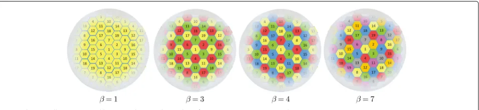
In this section, we illustrate the analytical contributions by simulation results for a symmetric hexagonal network topology. We apply the classic 19-cell-wrap-around struc-ture to avoid edge effects and guarantee consistent simu-lated performance for all cells; see Fig. 1. Each hexagonal cell has a radius ofr = 500 m and is surrounded by six interfering cells in the first tier and 12 in the second tier. To achieve a symmetric pilot allocation in this network, the pilot reuse factor can beβ ∈ {1, 3, 4, 7}. For each pilot reuse policy, the same subset of pilots are allocated to the cells with the same color, and pilots in each cell are allocated randomly to the users.
The user locations are generated independently and uni-formly at random in the cells, but the distance between each user and its serving BS is at least 0.14r. For each
user location z ∈ R2, a classic pathloss model is con-sidered, where the variance of the channel attenuation is dj(z)= zC−(bz)
jκ. The vectorbj∈R
2is the location of the
BS in cellj,κis the pathloss exponent, and·denotes the Euclidean norm.C(z) > 0 is independent shadow fading for some user locationzwith 10 log10C(z)∼N
0,σsf2
.
In the simulation, we assumeκ = 3.7,σsf2 = 5 and the coherence block lengthS=1000.6
5.1 Benefits of the proposed M-MMSE scheme
In this subsection, we show the benefits of our M-MMSE scheme over the conventional alternatives. Statis-tical channel inversion power control is applied to both pilot and uplink payload data, i.e.,plk =τlk = dl(ρzlk) [19]. Thus, during the uplink phase, the average effective chan-nel gain between users and their serving BSs is constant:
Eplkhllk2
= Eτlkhllk2
= Mρ. Then, the aver-age uplink SNR per antenna and user at its serving BS is
ρ/σ2. This is a simple but effective policy to avoid near-far blockage and, to some extent, guarantee a uniform user performance in the uplink. For downlink payload data transmission, the transmit powerlkis selected according to Theorem 5 to achieve the same downlink SE at each user as in the uplink. In our simulation,ρ/σ2is set to 0 dB to allow for decent channel estimation accuracy, and the time proportions for the uplink and downlink are set toζul=ζdl= 1
2.
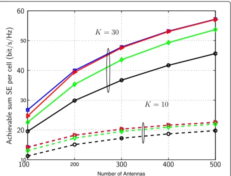
To verify the accuracy of the large-scale approximations from Section 3, 10,000 independent Monte-Carlo chan-nel realizations are generated to numerically calculate the joint achievable SE in (23). The numerical results and their approximations from Theorems 3 and 4 are shown in Fig. 2. As shown in the figure, the achievable sum SE increases with β for the considered range of values.
Fig. 2Achievable sum SE as a function of the number of antennasM, forβ∈ {1, 3, 4, 7},K=10 andc=0.0001
This is because a largerβ results in a lower level of pilot contamination, which contributes to a higher channel estimation accuracy, and thereby increases the achievable SE. Moreover, a largerβprovides more estimated channel directions in the construction of the M-MMSE scheme; thus, a higher inter-cell interference suppression can be achieved.7Figure 2 shows that the numerical results and the large-scale approximations match very well, even for smallMand smallK.
To show explicitly the advantages of our M-MMSE scheme, simulation results for the MF scheme from [8], the multi-cell ZF (M-ZF) scheme from [19], and the S-MMSE scheme from [12, 15, 16] (and given in (15)) are provided for comparison. The same downlink power allo-cation from Theorem 5 and normalization based on (19) are applied for all precoders. Notice thatM−βK > 0 is needed for the M-ZF scheme; thus, the minimum value ofMfor M-ZF isβK+1. Simulation results are shown in Figs. 3–4 for β = 1 and β = 3, respectively. The MF scheme always achieves the lowest performance since it does not suppress any interference. Compared to S-MMSE, our proposed M-MMSE always achieves a higher sum SE, and the advantage becomes more significant asβ and/orKincreases. Forβ = 3 andM = 200, the SEs of M-MMSE are 30% and 42% higher than those of S-MMSE forK =10 andK=30, respectively. Forβ =7, the gains increase to 42% and 82% forK =10 andK =30, respec-tively (the related figure is omitted for brevity). The higher performance gain at larger K or β comes from the fact that more channel directions can be learned and utilized for interference suppression by M-MMSE, while S-MMSE always usesKdirections regardless ofβ. The advantage of M-MMSE over M-ZF is minor for smallβand smallK, but the gain becomes notable asβandKgrow. Since the com-plexity of our M-MMSE scheme is the same as for M-ZF,
Fig. 4Achievable sum SE of M-MMSE (squares), M-ZF (triangles), S-MMSE (diamonds), and MF (circles) withβ=3
and M-ZF can sometimes achieve very low SE for smallM, in general, our scheme is the a better choice if high system SE is desirable.
Since the optimal pilot reuse factor may be different for different schemes, we further compare the performance when each scheme uses its own separately optimizedβo∈ {1, 3, 4, 7}. The results are shown in Fig. 5. We notice that our M-MMSE scheme prefers a higher pilot reuse policy
βo = 7 while S-MMSE prefersβo =3. Moreover, our M-MMSE achieves a significantly higher performance than S-MMSE, also when considering separately optimized pilot reuse factors.
5.2 Effectiveness of joint power control
In this subsection, the effectiveness of the proposed power control scheme is testified. Statistical power controlplk =
Fig. 5Achievable sum SE of M-MMSE (squares), M-ZF (triangles), S-MMSE (diamonds), and MF (circles) with optimizedβo∈ {1, 3, 4, 7} andK=30
ρ
dl(zlk) is still applied for pilots, while the uplink payload power τjk is optimized. ρ/σ2 is still set to 0 dB, and the maximal transmit power Pmaxin P is selected as in Section 5.1. Results for equal maximum power allocation (i.e.,τlk=Pmax) are provided as a baseline. We also apply Algorithm 1 to the instantaneous SINR in (12) for com-parison. The following results are obtained forM = 300 andK = 10. After generating user locations and shadow fading realizations, the 9 users with the worst channel conditions in the whole network are dropped to provide 95% coverage.
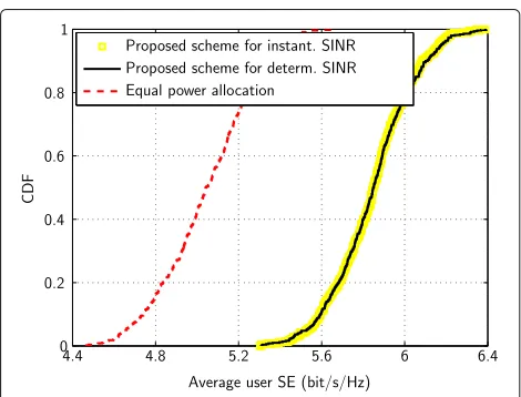
We first consider the average per-user SE which is cal-culated as the network sum SE divided by the number of served users. The cumulative distribution functions (CDFs) over user locations are shown in Fig. 6 forβ =3. As seen from the figure, the CDF curve with long-term power control based on Algorithm 1 coincides with those with short-term power control optimized for the instanta-neous SINR at every coherence block, which validates that there is negligible loss associated with our power control based on the large-scale SINR approximation. Further-more, compared with the equal power allocation policy, the average user SEs can be significantly improved by our power control scheme. At the 50th percentile, 16% increase can be achieved by our scheme.
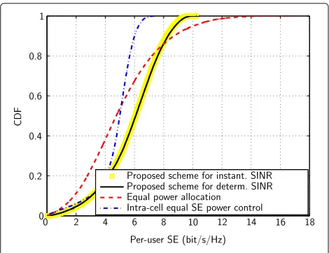
We also analyze how the per-user SE at different parts of the cells is affected by our power control. Results are provided for the power control proposed in [35], which tries to provide equal SE for users in the same cell so that, to some extent, intra-cell user fairness is guaran-teed. The CDF of the per-user SE is shown in Fig. 7. With our algorithm, in contrast to equal power alloca-tion, the majority of the users can enjoy higher SEs at the cost of a small degradation for the users with the strongest channels. This is because our algorithm assigns
Fig. 7CDFs of per-user SE withβ=3
lower transmit powers to the few users close to the center of the cell and higher powers to the many users fur-ther away, so that the interference caused by the former to the latter is reduced. In this way, our algorithm sup-presses interference. Compared with the power control from [35], our algorithm provides essentially the same SE for the weakest users, while pushing the SE of the majority of the users to higher values. Despite the larger SE variations, the proposed power control brings a bet-ter type of user fairness than the scheme from [35] since the strong users get higher SEs without degrading for the weakest ones.
6 Conclusions
In this paper, a new state-of-the-art M-MMSE scheme is proposed, which includes an uplink M-MMSE detec-tor and a downlink M-MMSE precoder. It brings very promising sum SE gains over S-MMSE and other single-cell schemes by actively suppressing both intra-cell and inter-intra-cell interference. Since imperfect CSI is accounted for in our scheme, the gains obtained by our scheme are likely to be achievable in practical systems. Furthermore, large-scale approximations of the uplink and downlink SINRs are derived for the proposed M-MMSE scheme. The approximations are very accurate even for small system dimensions and are easy to compute since they only depend on long-term statistics. Hence, the expressions can be utilized for efficient performance anal-ysis, without the need for Monte-Carlo simulations. The SINR approximations can further be used for power con-trol design, and a low-complexity power concon-trol algorithm for sum SE maximization is proposed. The proposed algo-rithm brings a notable sum SE gain and also provides good user fairness compared to the equal power alloca-tion policy. Since the SINR approximaalloca-tions depend only
on long-term statistics, the complexity of the algorithm can be spread over a long time period.
Endnotes
1These schemes have several names in the
litera-ture: MF is also known as maximum ratio combin-ing/transmission; ZF is also known as channel-inversion; and regularized ZF (RZF) is a simple variation on S-MMSE.
2In practice, only the propagation channels are
recip-rocal, while the hardware used for uplink and downlink communication is not. This requires reciprocity-calibration of the hardware, but there are many algorithms for this, and the variations are slow so the calibration overhead is negligible [34].
3Notice that √1
BV =
1
√
B[v1,. . .,vB]∈ C
B×B is an orthogonal basis for aBdimensional space. Therefore, a singular value decomposition of j is j = B1VAjVH, where Aj is a diagonal matrix with its bth element as ajb=B/φ˜jb. Then, (7) is obtained.
4Only multiplications are counted in the complexity
comparison, since additions and subtractions have a neg-ligible complexity in comparison.
5This method works well in massive MIMO systems
due to channel hardening—the effective channel is rela-tively close to its mean, while the performance loss would be large in a small-scale MIMO system.
6This coherence block can, for example, have the
dimensions ofTc=10 ms andWc=100 kHz.
7One should notice thatK andβ cannot be increased
indefinitely due to the prelog loss in the achievable SE.
Appendix 1
Proof of Theorem 3
Definej=HˆV,jjHˆHV,j+σ2+ϕj
IM −1
, then the
M-MMSE detector in (13) is gjk = jhˆjjk. We omit the superscript “M-MMSE” in the proof for brevity. In the following proof, we useto denote the almost sure con-vergence such that a b representsa−b −−−−→a.s.
M→∞ 0.
Define
1. HˆV,jlk=
ˆ
hV,j1, ...,hˆV,j(ilk−1),hˆV,j(ilk+1), ...,hˆV,jB ,
2. jlk=diagλj1, ...λj(ilk−1),λj(ilk+1), ....,λjB
, 3. j=diag{ ˜φj1, ...,φ˜jB},
4. jjk=HˆV,jjkjjkHˆHV,jjk+σ2+ϕj
IM −1
,
5. j=Mjandjjk=Mjjk,
Lemma 1 Lethˆjlkandh˜jlkdenote the MMSE estimate of
hjlkas in(5)and its estimation error, respectively, then
ˆ which can be applied since jjk has uniformly bounded spectral norm with respect toM, becauseϕjscales asK and MK > 0 by assumption; thus, ϕMj > 0 for allM. (c)
, which is obtained by Theorem 1 for
T=jjandρ= σ2M+ϕj. Lemma 12 in [36], respectively.
We use Lemma 1 in the following to determine the asymptotic behavior of each term in (12).
Signal power
By the continuous mapping theorem [38], we further obtain
Thus, by the dominated convergence theorem [39] and the continuous mapping theorem, we have
E
The computation depends on which pilots that are used.
ilm=ijk =i0
In this case, userk in celljuse the same pilot sequence as user m in cell j, and there will be coherence pilot contaminated interference. Since
where in step (a) the first term remains and the sec-ond term vanishes according to Lemma 1. Indicated by the dominated convergence theorem and the continuous mapping theorem, we have
ilm=ijk
In this case, two users have different pilots, such that
jlmjjkjjkhjlm
1+λjijkφ˜jijkδj
2 , (44)
where step(a)follows from Lemma 1 in [12] and the def-inition ofjjk. Step(b) follows from Lemma 12 in [36], Lemma 14.3 in [37], and Theorem 1. It remains to obtain a deterministic equivalent of the numerator in (44). Define j,jk,lm =−1
jjk −λjilmhˆV,jilmhˆHV,jilm
−1
, then according to Lemma 2 in [12] we have
Plugging (45) into the numerator of (44), we obtain
hHjlmjjkjjkhjlm=hHjlmj,jk,lmj,jk,lmhjlm →(intf. 1)
Deterministic equivalent of (intf. 1): Define j,jk,lm = Mj,jk,lm, then following similar procedures as before, it is straightforward to show that
hHjlmj,jk,lmj,jk,lmhjlm
Deterministic equivalent of(intf. 2):Instead of tackling the expression in (intf. 2) directly, we derive the deter-ministic equivalents of its numerator and denominator,
respectively. Plugging hjlm = ˆhjlm + ˜hjlm and hˆjlm = in [37]. Similarly, we have
ˆ equivalents of the denominator and numerator are given as 1+ λjilmφ˜jilmδj and
1
Mλjilmplmd 2
j(zlm)φ˜ji2lmϑjδj, respec-tively. According to the continuous mapping theorem,
(intf. 2)− −2φ˜
Deterministic equivalent of(intf. 3):Based on the tech-niques used to characterize (intf. 1) and (intf. 2), it is straightforward to show that
(intf. 3)−
Plugging (46), (50), and (51) into (44), we have that
Noise power and Theorem 2. Then, by the dominated convergence theorem, we have
Finally, by the continuous mapping theorem, we arrive at the expression in (29).
Appendix 2
Proof of Theorem 4
Except for the channel variance varhHjjkwjk
of the signal power and the interference in (22) can be cal-culated by following similar procedures as in Appendix 1. Thus, only the channel variance is considered here.
Define c = ˆhHjjkjhˆjjk, c¯ = E
where the last step is due to the fact thathˆjjkis indepen-dent ofh˜jjkand thatE{b} =0.
Sincecand¯care bounded, this implies by the dominated convergence theorem thatE{|c− ¯c|} → 0 asM → ∞. means thatB−Ais positive semi-definite). Sinceϕ2j scales asK2or equivalently asM2, and tr(jjkˆ C
The work is supported by National Basic Research Program (2012CB316000), National Natural Science Foundation of China (61201192), National High Technology Research Development Program of China (2014AA01A703), National S&T Major Project (2014ZX03003003-002), Tsinghua-Qualcomm Joint Research Program, Keysight Technologies, Inc., ELLIIT, the CENIIT project 15.01, and the FP7-MAMMOET project.
Authors’ contributions
All authors contributed to this work, and the authors are listed in the order of their contribution. All authors read and approved the final manuscript.
Competing interests
The authors declare that they have no competing interests.
Publisher’s Note
Springer Nature remains neutral with regard to jurisdictional claims in published maps and institutional affiliations.
Author details
1Department of Electronic Engineering, Research Institute of Information
Technology, Tsinghua University, Beijing 100084, China.2Department of
Electrical Engineering (ISY), Linköping University, SE-58183 Linköping, Sweden.
Received: 11 August 2016 Accepted: 28 March 2017
References
1. G Caire, N Jindal, M Kobayashi, N Ravindran, Multiuser MIMO achievable rates with downlink training and channel state feedback. IEEE Trans. Inf. Theory.56(6), 2845–2866 (2010)
2. G Caire, S Shamai, On the achievable throughput of a multiantenna Gaussian broadcast channel. IEEE Trans. Inf. Theory.49(7), 1691–1706 (2003)
4. D Gesbert, M Kountouris, RW Heath, CB Chae, T Salzer, From single user to multiuser communications: shifting the MIMO paradigm. IEEE Signal Process. Mag.24(5), 36–46 (2007)
5. V Stankovic, M Haardt, Generalized design of multiuser MIMO precoding matrices. IEEE Trans. Wireless Commun.7(3), 953–961 (2008)
6. T Yoo, A Goldsmith, On the optimality of multiantenna broadcast scheduling using zero-forcing beamforming. IEEE J. Sel. Areas Commun. 24(3), 1912–1921 (2006)
7. EG Larsson, O Edfors, F Tufvesson, TL Marzetta, Massive MIMO for next generation wireless systems. IEEE Commun. Mag.52(2), 186–195 (2014) 8. TL Marzetta, Noncooperative cellular wireless with unlimited numbers of
base station antennas. IEEE Trans. Wireless Commun.9(1), 3590–3600 (2010)
9. F Rusek, D Persson, KL Buon, EG Larsson, TL Marzetta, O Edfors, F Tufvesson, Scaling up MIMO: opportunities and challenges with very large arrays. IEEE Trans. Signal Process.30(1), 40–60 (2013)
10. HQ Ngo, EG Larsson, TL Marzetta, Energy and spectral efficiency of very large multiuser MIMO systems. IEEE Trans. Commun.61(4), 1436–1449 (2013)
11. E Björnson, J Hoydis, M Kountouris, M Debbah, Massive MIMO systems with non-ideal hardware: energy efficiency, estimation, and capacity limits. IEEE Trans. Inf. Theory.60(11), 7112–7139 (2014)
12. J Hoydis, S ten Brink, M Debbah, Massive MIMO in the UL/DL of cellular networks: how many antennas do we need? IEEE J. Sel. Areas Commun. 31(2), 160–171 (2013)
13. E Björnson, E Jorswieck, Optimal resource allocation in coordinated multi-cell systems. Found. Trends Commun. Inf. Theory.9(2–3), 113–381 (2013)
14. TL Marzetta, inProc. IEEE Asilomar Conference on Signals, Systems and Computers. How much training is required for multiuser MIMO? (IEEE, Pacific Grove, 2006), pp. 359–363. 29 Oct.-1 Nov. 2006
15. KF Guo, Y Guo, G Fodor, G Ascheid, inProc. IEEE International Conference on Communications (ICC). Uplink power control with MMSE receiver in multi-cell MU-massive-MIMO systems (IEEE, Sydney, 2014), pp. 5184–5190 16. N Krishnan, RD Yates, NB Mandayam, Uplink linear receivers for multi-cell
multiuser MIMO with pilot contamination: large system analysis. IEEE Trans. Wireless Commun.13(8), 4360–4373 (2014)
17. HQ Ngo, M Matthaiou, EG Larsson, in2012 Swedish Communication Technologies Workshop (Swe-CTW). Performance analysis of large scale MU-MIMO with optimal linear receivers (IEEE, Lund, 2012), pp. 59–64 18. J Hoydis, S ten Brink, M Debbah, inProc. of 49th Allerton. Massive MIMO:
How many antennas do we need? (IEEE, Monticello, 2011), pp. 545–550 19. E Björnson, EG Larsson, M Debbah, Massive MIMO for maximal spectral
efficiency: How many users and pilots should be allocated? IEEE Trans. Wireless Commun.15(2), 1293–1308 (2016)
20. J Jose, A Ashikhmin, TL Marzetta, S Vishwanath, Pilot contamination and precoding in multi-cell TDD systems. IEEE Trans. Wireless Commun.10(8), 2640–2651 (2011)
21. KF Guo, G Ascheid, inProc. IEEE Wireless Communications and Networking Conference (WCNC). Performance analysis of multi-cell MMSE based receivers in MU-MIMO systems with very large antenna arrays (IEEE, Shanghai, 2013), pp. 3175–3179
22. D Tse, P Viswanath,Fundamentals of Wireless Communication. (Cambridge University Press, New York, 2005)
23. JW Silverstein, ZD Bai, On the empirical distribution of eigenvalues of a class of large dimensional random matrices. J. Multivariate Anal.54(2), 175–192 (1995)
24. M Chiang, P Hande, T Lan, CW Tan, Power control in wireless cellular networks. Foundations Trends® Netw.2(4), 381–533 (2008)
25. D Gesbert, SG Kiani, A Gjendemsjo, GE Oien, Adaptation, coordination, and distributed rresource allocation in interference-limited wireless networks. Proc. IEEE.95(12), 2393–2409 (2007)
26. ZQ Luo, W Yu, An introduction to convex optimization for
communications and signal processing. IEEE J. Sel. Areas Commun.24(8), 1426–1438 (2006)
27. M Chiang, Balancing transport and physical layers in wireless multihop networks: jointly optimal congestion control and power control. IEEE J. Sel. Areas Commun.23(1), 104–116 (2005)
28. IC Paschalidis, W Lai, D Starobinski, Asymptotically optimal transmission policies for large-scale low-power wireless sensor networks. IEEE/ACM Trans. Netw.15(1), 105–118 (2007)
29. K Kumaran, L Qian, Uplink scheduling in CDMA packet-data systems. Wireless Netw.12(1), 33–43 (2006)
30. M Charafeddine, A Sezgin, A Paulraj, inProc. of 45th Allerton. Rate region frontiers forn-user interference channel with interference as noise (Allerton House, UIUC, Illinois, 2007). September 26–28, 2007 31. ZQ Luo, SZ Zhang, Dynamic spectrum management: complexity and
duality. IEEE J. Sel. Topics Signal Process.2(1), 57–73 (2008) 32. M Chiang, CW Tan, DP Palomar, D O’Neill, D Julian, Power control by
geometric programming. IEEE Trans. Wireless Commun.6(7), 2640–2651 (2007)
33. CW Tan, M Chiang, R Srikant, inProc. IEEE INFOCOM. Fast algorithms and performance bounds for sum rate maximization in wireless networks (IEEE, Rio de Janeiro, 2009), pp. 1350–1358
34. J Vieira, S Malkowsky, K Nieman, Z Miers, N Kundargi, L Liu, IC Wong, V Öwall, O Edfors, F Tufvesson, inProc. IEEE GLOBECOM Workshop. A flexible 100-antenna testbed for massive MIMO, (2014), pp. 287–293 35. H Yang, TL Marzetta, inProc. IEEE Vehicular Technology Conference (VTC
Fall). A macro cellular wireless network with uniformly high user throughputs (IEEE, Vancouver, 2014), pp. 1–5
36. J Hoydis, Random matrix methods for advanced communication system. Ph.D dissertation, Supélec, Gif-Sur-Yvette, France (2012)
37. R Couillet, M Debbah,Random Matrix Methods for Wireless Communications. (Cambridge University Press, New York, 2011) 38. AW van der Vaart,Asymptotic Statistics (Cambridge Series in Statistical and
Probabilistic Mathematics). (Cambridge University Press, New York, 2000) 39. P Billingsley,Probability and Measure, 3rd ed. edn. (John Wiley & Sons, Inc.,
New York, 1995)
Submit your manuscript to a
journal and benefi t from:
7Convenient online submission 7 Rigorous peer review
7Immediate publication on acceptance 7 Open access: articles freely available online 7High visibility within the fi eld
7 Retaining the copyright to your article