R E S E A R C H
Open Access
Maximum likelihood detection for coded
combinerless LINC-OFDM systems
Wen-Rong Wu
1, Sheng-Lung Cheng
1*and Ying-Pei Hsu
2Abstract
Owning to the high peak-to-average power ratio problem, the power efficiency of orthogonal-frequency-division-multiplexing (OFDM) systems is usually low. It deteriorates in millimeter wave systems in which the design of an efficient linear power amplifier is much more challenging. The linear-amplification-with-nonlinear-component (LINC) technique can serve as a remedy, decomposing the input signal into two constant-envelop component signals followed by high-efficient nonlinear amplifiers. However, the power combiner, a key component used to combine the amplified signals, is difficult to implement. Combinerless LINC systems employ two transmit antennas such that two component signals can be naturally combined at the receiver. Unfortunately, the performance of combinerless LINC-OFDM systems is seriously degraded if difference, even small, exists between the two channels. The maximum likelihood (ML) receiver can effectively solve the problem; however, its computational complexity is prohibitedly high. We propose a coded combinerless LINC-OFDM system, including a convolutional encoder and a list Viterbi algorithm (LVA) decoder, to solve the problem. The LVA can provide a small number of candidates for the ML detector,
dramatically reducing the required computational complexity. We also utilize an enhanced zero-forcing equalizer such that the soft-demapping operation can be effectively conducted. Finally, we propose a simple iterative interference cancellation scheme to further enhance the performance. Simulations show that the proposed
combinerless LINC-OFDM system can outperform the conventional OFDM while the consumed power is much lower.
Keywords: Linear-amplification-with-nonlinear-component (LINC), Orthogonal-frequency-division-multiplexing (OFDM), Peak-to-average power ratio (PAPR), Maximum likelihood (ML), List Viterbi algorithm (LVA)
1 Introduction
As known, power amplifier (PA) is the most power-hungry device in wireless transceivers. The PA efficiency heav-ily depends on the peak-to-average power ratio (PAPR) of the transmit signal. By allocating the modulated sym-bols on orthogonal subcarriers, orthogonal-frequency-division-multiplexing (OFDM) can have higher spectral efficiency and lower equalization complexity than conven-tional single-carrier systems [1]. For these reasons, OFDM has been widely adopted in today’s wireless systems. How-ever, combining of multiple modulated signals results in high-variant signal amplitude, yielding the high PAPR problem. A high PAPR signal requires a large PA power back-off, resulting in low PA efficiency. Recently, millime-ter wave (mmWave) communication has been considered
*Correspondence: [email protected]
1Institute of Communications Engineering, National Chiao Tung University, University Road, 30010 Hsinchu, Taiwan
Full list of author information is available at the end of the article
as a promising technology for future fifth-generation (5G) systems [2]. However, the PAPR problem will become even worse in mmWave systems. Designing high-linearity mmWave PAs remains a big challenge even with today’s technology [3, 4].
In order to reduce the PAPR of the OFDM signal, some baseband signal processing methods, like amplitude clip-ping and filtering [5, 6], partial transmit sequence (PTS) [7, 8], coding [9], and selected mapping (SLM) [10], have been proposed. These methods can reduce the PAPR to some extent with the price of higher processing com-plexity or data redundancy. Another useful approach is to modify the architecture of RF signal amplification such that the linearity or the power efficiency can be enhanced [11–16].
Conventional transmitters use Cartesian modulation to form complex transmit signal. As a result, linear amplifi-cation is required, yielding large back-off for high PAPR
signal. Polar modulation, decomposing the complex trans-mit signal into amplitude and phase signals, allows the application of two different amplifications for the two sig-nals. In the envelope-elimination-and-restoration (EER) transmitter [12], the phase signal (constant-enveloped) is amplified by a high-efficiency nonlinear PA and the amplitude signal by a linear PA. Then, the amplified amplitude signal is used to modulate the amplified phase signal, yielding the original signal amplified by an equiva-lent high-efficiency linear PA. Another polar transmission technique is known as envelope tracking (ET) [13] in which the amplitude signal is used to control the supply voltage of a linear PA such that the PA can always be oper-ated in the high-efficiency regions. With a different opera-tion principle, the Doherty transmitter [14] combines two equal-capacity PAs, referred to as carrier and peaking, in the quarter-wavelength network. Only the carrier PA is active when the amplitude of the signal is lower than the half of the peak amplitude, and both PAs are active when the signal amplitude is larger than the half of the peak amplitude. In the above approaches, the transmit signal is decomposed into two amplified by two PAs and there exist various kinds of implementation issues. For example, sig-nal bandwidth is expanded and the stringent timing align-ment between two signals is difficult. Still, there is another well-known approach referred to as linear-amplification-with-nonlinear-component (LINC) technique [17] to be described in the next paragraph.
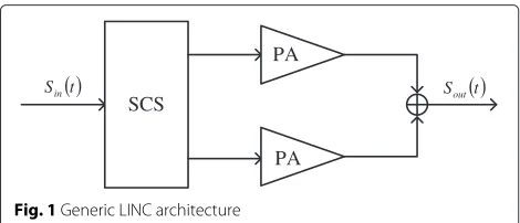
In the LINC transmitter (also called as the outphasing in [18]), the modulated signal is passed to a signal com-ponent separator (SCS) [17, 19] and then decomposed to two constant-envelope component signals. Since the two component signals are both constant-enveloped, they can be amplified by high-efficiency nonlinear PAs. After the amplification, the two component signals are then com-bined by a power combiner to obtain a linearly amplified signal. Figure 1 shows the block diagram of a LINC sys-tem. There are two main problems in the LINC syssys-tem. The first one is that the two signal paths cannot be per-fectly balanced and the combined signal will be distorted. Several methods for solving the PA imbalanced problem were discussed in [20, 21]. The second problem is the
SCS
PA
PA t
Sin Soutt
Fig. 1Generic LINC architecture
performance of the combiner. For good combining linear-ity, the matched combiner is generally used. However, the matched combiner will induce the severe power loss for high PAPR signals. Simulation results in [22] show that the power efficiency of the LINC transmitter with the matched power combiner is similar to that of the con-ventional transmitter without LINC. In [23], a multilevel LINC architecture which can increase the efficiency of the matched combiner was proposed. In [24], the Chireix combiner was proposed. By adding the shunt resistors and the transmission line coupler after both PAs, the power efficiency can be improved [22, 24]. However, the linear-ity of this design is degraded. This approach trades the linearity for the power efficiency.
To solve the problems of the conventional LINC, a com-binerless LINC-OFDM system (CL-LINC-OFDM) was then developed [25]. With two closed-spaced antennas for signal transmission, the use of the power combiner can be avoided. Two component signals can be naturally com-bined in the air and received at the destination. Simulation results in [25] show that the efficiency of the combinerless LINC system is about 6 dB higher than the LINC system with the matched combiner. An experimental demonstra-tion of the combinerless LINC system was also shown in [26]. However, the performance of the CL-LINC-OFDM system will be seriously affected if there is difference, even small, between the channels that the two component sig-nals propagate. This effect is critical but not considered in [25]. To overcome, a space-time coded combinerless LINC system was proposed in [27]. The price to pay for this approach is that the transmission rate is reduced by half. Yet, a beamforming outphasing system was pro-posed in [28]. Still, the throughput will be affected when the phase error of the beamforming is considered. In our previous work [29], an enhanced equalization method is proposed using the LINC property, but its performance is still far away from the conventional OFDM system. In [30] , several suboptimum ML detection methods for the CL-LINC-OFDM were proposed, reducing the com-putational complexity to some extent. It was shown that with the ML detection, LINC-OFDM can have similar performance as conventional OFDM. However, the com-putational complexity is still far too high for real-world applications.
for the LVA can be obtained. Finally, we propose a sim-ple iterative interference cancellation (IC) method that can further enhance the performance of the proposed CL-LINC-OFDM system. Simulations show that the proposed CL-LINC-OFDM system can outperform the conven-tional OFDM while the consumed power is much lower. The remainder of this paper is organized as follows. The second section describes the system model, the prob-lems of CL-LINC-OFDM systems, and existing solutions. The third section describes the equalizer that we use. The fourth section shows the proposed ML detection with the LVA. The fifth section analyses the power efficiencies of conventional OFDM and CL-LINC-OFDM systems. The sixth section provides simulation results to evaluate the performance of the proposed algorithms, and the seventh section gives conclusions.
2 System model
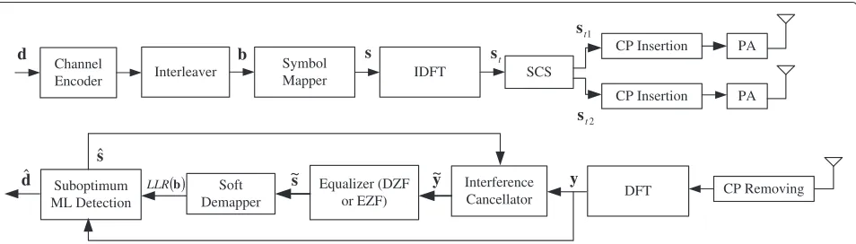
Figure 2 shows the block diagram of the proposed coded CL-LINC-OFDM system. In the figure, d = [d0,. . .,dN−1]T denotes a length-N bit sequence to be
transmitted with an OFDM symbol. With the channel encoding and symbol mapping operations,dis transferred to a frequency-domain OFDM symbol denoted as s = [s0,. . .,sM−1]T, where M is the number of subcarriers.
Then, s is passed through the inverse-discrete-Fourier-transform (IDFT) operation, and the output is expressed by st =[st,0,. . .,st,M−1]T. Note thatst does not include the cyclic prefix (CP). The SCS [19] decomposesstinto two constant-envelope component symbols denoted as
st1= st
2 +e=[st1,0,. . .,st1,M−1]
T, (1)
and
st2= st
2 −e=[st2,0,. . .,st2,M−1]
T, (2)
where
e=
⎡ ⎣jst,0
2
V02
|st,0|2−
1,. . .,jst,M−1
2
V02
|st,M−1|2−
1
⎤ ⎦ T
.
(3)
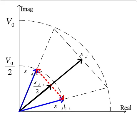
In (3), V0 is the peak magnitude for the OFDM
sig-nal. If any|st,i|is larger thanV0,|st,i|will be clipped and substituted by V0, and the resultant component signal
will be V0
2 ·
st,i
|st,i|. The value ofV0should be chosen as a compromise between the level of clipping noise and the magnitude of PAPR. IfV0is large, the clipping noise will
be small and the PAPR will be large and vice versa. Let the
ith component ofst,st1, andst2be denoted byst,i,st1,i, and st2,i, respectively. Figure 3 shows the relationship of st,i, st1,i, andst2,i. With CP added,st1andst2are delivered to
nonlinear PAs and then transmitted by two closed-spacing antennas, TX1 and TX2. Denote the channel impulse
responses between TX1, TX2 and the receiver ash1 =
[h1,0,. . .,h1,P−1]T and h2 =[h2,0,. . .,h2,P−1]T,
respec-tively, wherePis the number of the channel taps. For the channel corresponding to the same transmit antenna, we assume that each tap is statistically independent.
At the receiver, the CP of the received OFDM symbol is first removed and then anM-point DFT is applied. The received frequency-domain signal can then be written as
y=H1s1+H2s2+n, (4)
where n is an M×1 additive white Gaussian noise (AWGN) vector with a covariance matrix ofσ2
nI;H1and
H2 are twoM×M diagonal matrices with diagonal
ele-ments being equal to the DFTs ofh1andh2, respectively;
s1ands2are the DFTs ofst1andst2, respectively.
From the definitions ofst1andst2in (1) and (2), we can
simply see thats = s1+s2sincest = st1+st2. We can
also see that the CL-LINC-OFDM system is equal to the conventional OFDM system ifH1=H2. In real world, the
Channel
Encoder Interleaver
Symbol
Mapper IDFT SCS
CP Insertion
CP Insertion
PA
PA
s st
1
t
s
2
t
s
CP Removing DFT
Suboptimum ML Detection
y sˆ
dˆ
d b
b
LLR Interference
Cancellator Equalizer (DZF
or EZF) Soft
Demapper
y ~ s
~
0
two channel responses cannot be exactly the same, though they are close. We may simply assume thatH1 ≈H2and
apply a zero-forcing (ZF) equalizer to recovers. LetH =
(H1+H2)/2 andˆsbe the ZF estimate ofs. Then, we have
ˆ
s=H−1y. (5)
Unfortunately, it is found that the performance of CL-LINC-OFDM can be seriously degraded if there exists a difference betweenH1andH2. This is because the
chan-nel difference will introduce a strong self-interference. For reference convenience, we refer the ZF equalizer in (5) as the direct ZF (DZF) equalizer.
In [27], the idea of space-time coding is applied in the CL-LINC-OFDM system to solve the problem. The Alamouti code is used in a way that for one symbol time st1andst2are transmitted byTX1andTX2, respectively,
and for the next symbol time,−s∗t2ands∗t1are transmitted. Using two consecutive received OFDM symbols and some simple operations, we can obtain two signals˜s1and˜s2as
˜
secutive OFDM symbols. From the above equations, it is simple to see thatscan be recovered without any interfer-ence; the estimate ofsis given by(H1HH1 +H2HH2)−1(˜s1+
˜
s2). However, the main drawback of this approach is that
the throughput is reduced by half.
Except for the DZF method, the well-known ML method can also be applied to (4). Let the number of can-didates forsbeK,skbe thekth candidate, ands1,kands2,k
be the two component signals ofsk. The ML problem can then be formulated as:
ˆ
k=arg min
1≤k≤Ky−(H1s1,k+H2s2,k)
2. (8)
It is readily to see that the computational complexity of (8) is prohibitedly high and the solution of (8) is almost impossible to obtain. Let the QAM size of each subcar-rier be Q. Then, K will be equal to QM. For a simple OFDM system with QPSK modulation and 64 subcarri-ers,K=464! Note that for eachk, we have to conduct one
DFT and one IDFT operations. The suboptimum solu-tion proposed in [30] is to alleviate this problem; only the detected symbols (with the DZF method) considered to be unreliable are taken in the ML search. Also, the sub-carriers are grouped and the ML search is only conducted for each individual group, sequentially. LetUbe the num-ber of unreliable detected symbols,Gbe the number of groups, andGdividesU. Then,K=GQU/G. As an exam-ple, let Q = 4, U = 12, and G = 3. Then, we have
K = 3×412/3 = 768. In other words, we have to con-duct 768 DFTs/IDFTs for each OFDM symbol. Although the complexity has been significantly reduced, it is still too high for practical systems.
In the following sections, we will propose a new approach to overcome the ML detection problem in (8). The main idea is to include a convolutional code (CC) channel encoder in the transmitter. The CC encoder in our system serves two purposes. The first one, as that in a typical communication system, is to enhance the transmission reliability. The second one is to reduce the number of the candidates considered in the ML detection. For the channel decoder to operate, we first need QAM symbols to be detected softly. The ZF method mentioned in (5) can do the job. However, its performance is not sat-isfactory. In the following section, we will first propose an enhanced ZF equalizer and then the corresponding soft demapper.
3 Enhanced equalization method
By (9) and the definition ofein (3), we can rewritest1
whereIis anM×Midentity matrix. The received signal in (4) can then be written as
y= 1
2(H1+H2)s+
j
2(H1−H2)FC(st)F
Hs+n, (11)
whereF andFH are used to denote the DFT and IDFT matrices; both of them are assumed to be unitary. Note thatst=FHs. From (11), we can see that the original rep-resentation of the received signals has been transferred to a form in whichsinstead ofs1ands2is involved. Also,
we can see that ifH1is not equal toH2, the second term
in the right-hand-side of (11) acts as an interference. The magnitude of this interference can be large even the dif-ference ofH1andH2is small, and this is the reason why
CL-LINC-OFDM with DZF performs not well.
Observe that the diagonal terms inC(st)are all greater or equal to zero which suggests that the means of these terms are not zero. If the non-zero-means can be removed, the level of the interference can be reduced. Define a positive valueμand rewrite (11) as
y=1
Then, the equalized symbols can be obtained as
ˆ
s=2(H1+H2)+jμ (H1−H2)
−1
y. (13)
Whenμis equal to zero, (13) is reduced to (5). So, (13) can be seen as a generalized form of the DZF equalizer when CL-LINC-OFDM transmission is applied. We name this equalizer as the enhanced ZF (EZF) equalizer.
The performance of the EZF equalizer strongly depends on the choice ofμ. We now derive an optimumμsuch that the average power of the interference is minimized. Define a vectorvas
v=[C(st)−μI]st. (14)
Thus, the interference vector in (12) is equal to j
2(H1−H2)Fv. To calculate the variance of the
interfer-ence in each subcarrier, we first calculate that ofv. When
Mis large, it is reasonable to approximate st as a zero-mean complex white Gaussian vector. The covariance matrix ofstcan be expressed asEsIwhereEsis the power
of the transmit signal. The mean of each component ofv is given by
Note that st,i is a zero-mean complex Gaussian
ran-dom variable such thatst,i have the same appearing probability, and the expectation value of (15) is zero. By the truth that each element ofv is also independent to each other, the covariance matrix of vcan be seen as an M×Mdiagonal matrix with the same diagonal term. Defining each diagonal term as σv2
and assuming V02
Es 1, we can approximate |st,i| as a Rayleigh distributed random variable and its probability density function (PDF) is given by
p|st,i|
To derive a closed-form solution for the third term of (17), we use an approximation that√1−x≈1−0.6x:
Substituting (18) and (19) to (17), we can obtain
σ2
v ≈ V02+
μ2−1E
s−2μE V0|st,i| −0.6| st,i|3
V0
!
= V02+μ2−1Es−μV0
" Esπ+
0.9μ√π
V0
E
3 2
s
= V02−Es− 1 4Es
# V0
π Es −
0.9√πEs V0
$2
+Es %
μ− 1 2
# V0
π
Es −
0.9√πEs V0
$&2
. (20)
Equation (20) is a quadratic function ofμ, and the opti-mum μ giving the smallest σv2 can be easily found as:
μ= V0
2
π
Es −
0.45√πEs V0
. (21)
The correspondingσv2can also be obtained as
σ2
v =V02−Es− 1 4Es
# V0
π
Es −
0.9√πEs V0
$2
=V02 '(
1− π 4
)
+(0.45π−1) Es
V02−
0.81πE2
s 4V04
*
.
(22)
Since the channel encoder is operated on the bit level, the equalized symbol sˆ has to be de-mapped into soft bits, a process referred to as soft-demapping [31]. Soft-demapping for OFDM systems requires to calculate the log-likelihood-ratio (LLR) for each transmit bit. To do that, we have to first calculate the signal-to-interference-noise ratio (SINR) of the equalized signal at each subcar-rier. Let the channel magnitude response of subcarrierk
beGk, and the variance of interference-plus-noise in the same subcarrier beσk2. Then, the SINR, denoted asγk, can be calculated as:
γk=
Es|Gk|2 σ2
k
. (23)
As mentioned, the covariance matrix ofv is diagonal. Then, the covariance matrix of the interference-and-noise vector in (12) is also diagonal and itskth diagonal term is given by
σ2
k =
|H1,k−H2,k|2
4 σ
2
v
+|
H1,k+H2,k
+jμH1,k−H2,k
|2
4 σ
2
c +σn2, (24)
whereH1,k is thekth diagonal component ofH1,H2,k is that of H2,σv2is the interference variance given in (22),
andσ2
c is the variance of the clipping noise. From (22), we see that the value of σv2 is an increasing function of
V0. Note that the value ofV0determines the PAPR of the
transmit signal. A smallerV0means a lower PAPR, higher
power efficiency, and lower interference in (12). How-ever, more signal samples will be clipped, increasing the
Channel
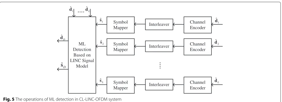
Fig. 5The operations of ML detection in CL-LINC-OFDM system
clipping noise level. From (12), we can obtain the channel magnitude response and then calculateγkas
γk=
where Ac is an equivalent amplitude after clipping. The values ofσc2andAccan be found as follows. Denote the clipped time-domain OFDM signal asˇst,iand the clipping ratio, equivalent to the square root of the PAPR value, as
κ = √V0
Es
. (26)
Since the time-domain OFDM symbol is approximated by a complex white Gaussian process, then
E{|ˇst,i|2} =Es (
1−e−κ2 )
. (27)
In [32], it was shown that the clipped signal can be modelled as where erfc(.)denotes the complementary error function, and
Finally, the LLR of theith bit transmitted atkth subcar-rier is obtained as
LLRbi,k bit of each element is 1 or 0. The LLR values are deemed as the de-mapped soft bits and then used as the input to the channel decoder.
As we can see from (30), the SINR at each subcarrier depends on the clipping ratio, κ. Ifκ is larger, the clip-ping noise will be smaller. At the same time, however, the interference will become stronger. We now derive a closed-form expression for the average SINR such that an optimumκ maximizing the average SINR can be found. Let the mean of each channel gain inH1andH2be
nor-malized to one. Then, the average channel gain for the EZF can be obtained as
E{|H1,k+H2,k Substituting (20), (26), (30), and (32) into (25) and tak-ing the expectation, we can obtain the average SINR (i.e.,
E{γk}), denoted by SINRa, of the CL-LINC-OFDM system with the EZF equalizer as
where SNR=Es/σn2andρ¯=
1+ρ+μ2(1−ρ). Using the value ofμin (21), we can rewrite the average SINR as
SINRa=
˜
ρ+1−e−κ2+
√
πκ
2 erfc(κ)
,2
(1−ρ)
+
κ21−π 4
+0.45π−1−0.81π4κ2
,
+ ˜ρe−κ2−κ√πerfc(κ)+2SNR−1
, (34)
where ρ˜ =
+
1+ρ+πκ2− 0.45κ 2(1−ρ)
,
. As we can see, the average SINR is a function ofρandκ. It can be shown that the average SINR is a concave function ofκ. For eachρ, we can then find the optimumκ by a simple numerical search.
4 Maximum likelihood detection with list Viterbi algorithm
In this section, we would consider the architecture of the decoder. As mentioned, the decoder serves two pur-poses: one is for the reduction of the bit-error-rate and the other is to reduce the computational complexity of the ML detector. We first reconsider the LINC-OFDM system shown in (11). Re-arrange (11) asy= ˜Hs+nwhereH˜ is anM×Mequivalent channel matrix given by
˜ H= 1
2(H1+H2)+
j
2(H1−H2)FC(st)F
H. (35)
Since the diagonal terms in the diagonal matrix C(st) are not all the same, the second term in (35) is not a diagonal matrix. It indicates that we cannot apply the carrier-by-carrier detection scheme as that in the con-ventional OFDM system. To have a better performance, we can apply the block-wise ML detection scheme as shown in (8). Unfortunately, as mentioned, the high com-putational complexity makes the general ML detection almost impossible to conduct. Here, we propose using the LVA [33] to reduce the number of candidates in the ML detection.
The LVA was originally proposed to enhance the per-formance of a concatenated coding system where the CC is used as the inner code. Since it is generally difficult to implement the joint decoding of both inner and outer codes, the inner code is softly decoded and the output is then used as the input for the outer decoder. Although the optimum decoding algorithm such as BCJR [34] can be applied, the required computational complexity is high. The LVA serves as an alternative soft decoding scheme by giving multiple decoded bit sequences. The conventional
Table 1Power efficiency comparison
PAPR (dB) μOFDM (PA
in [35]) (%) μLINC (PA in
[35]) (%) μLINC
(PA in [36]) (%)
6 2.25 9.19 15.15
8 1.42 5.82 9.59
10 0.9 3.68 6.07
VA outputs a bit sequence while the LVA outputs multi-ple. With more input sequences, the reliability of the outer decoding can be enhanced. Simulation results in [33] ver-ify that the performance of the concatenated coded system is indeed enhanced with the LVA. Here, we extend the use of the LVA to reduce the complexity of our ML problem.
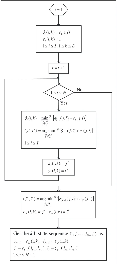
Now, we briefly describe the operations of the LVA. The LVA can be implemented as parallel or sequential pro-cessing fashion. Since the outputs of these two kinds of LVAs are the same, we only discuss the parallel LVA here. The difference between the LVA and the VA lies in that the LVA reserves multiple while the VA only one survival path for each state. Let the number of states in the trel-lis beIand the number of survivor paths to preserve be
L, the branch metric from statejto stateiat time(t−1) to t bectj,i, ctj,i = ∞when state i andj are not connected in the trellis diagram, andφt(i,k)be the kth lowest path metric to stateiat timet. Figure 4 gives the detailed operations of the parallel LVA. Here,εt(i,k)and γt(i,k) denote the state and the corresponding ranking which can reach φt(i,k) at time (t− 1). Also, min(k)(.) is thekth smallest value in the elements of(.). With the LVA, we can then obtainLstate sequences having the low-est path metrics. For thelth state sequence, we can derive its detected bits from the corresponding two consecutive
states asdˆl = +
ˆ
dl,0,dˆl,1,. . .,dˆl,N−1
,T .
Once we have theLbest detected bit sequences, we can use them as the candidates for the block-wise ML detec-tion. By this way, the number of the candidates can be dramatically reduced. Figure 5 shows the procedure of our low-complexity ML detector. Note that we have to regen-erate theLbest estimated symbol sequences, denoted by ˆ
s1,. . ..ˆsL, and each symbol sequence has to be re-encoded, re-interleaved, and symbol re-mapped. With the IDFT operation, we can obtain the L time-domain estimated
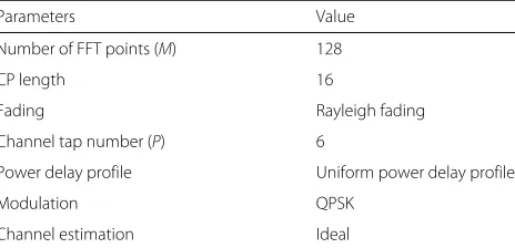
Table 2Simulation parameters
Parameters Value
Number of FFT points (M) 128
CP length 16
Fading Rayleigh fading
Channel tap number (P) 6
Power delay profile Uniform power delay profile
Modulation QPSK
3 4 5 6 7 8 9 10 11 12 13 0.5
1 1.5 2 2.5 3 3.5 4 4.5 5
V 0 2 /E
s(dB)
σv
2
Simulated values
Theoretical values
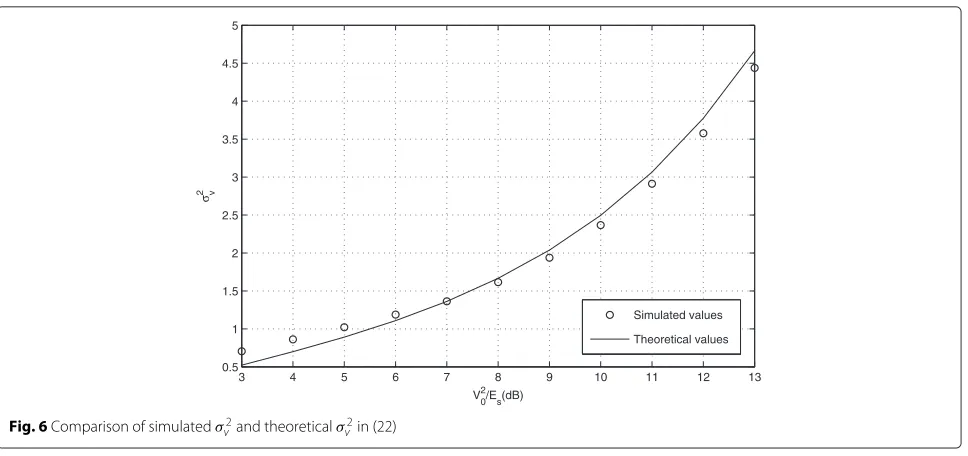
Fig. 6Comparison of simulatedσ2
v and theoreticalσv2in (22)
OFDM symbols, denoted them assˆt,1,. . ..ˆst,L. From (9) and (11), we can then obtain the ML detection from theL
candidates as
ˆ
l=arg min 1≤l≤Ly−
1
2(H1+H2)ˆsl−
j
2(H1−H2)FC(sˆt,l)F
Hˆs l. (36) Finally, the detected bit sequence can be obtained as ˆ
dD= ˆdˆl.
To further enhance the performance, we now propose a simple IC method. As seen from (12), the second term is the interference when the EZF is applied. Let the ML detected symbol besˆDandsˆD,t=FHˆsD. We can then use
C(ˆsD,t) to artificially generate the interference term and then conduct IC as
˜
y=y−ξj
2(H1−H2)F
C(sˆD,t)−μI
FHsˆD, (37)
where ξ is a cancellation factor and ξ < 1. Note that we only conduct partial IC in order to control the error propagation effect. With y˜, we can then apply the EZF equalizer, the LVA, and the ML detector again. This pro-cess can be repeated until a desired number of the iter-ations is met. The best partial cancellation factorξ can be determined by simulations. In general, its value can be increased as the iteration proceeds since the detected symbols would become more and more reliable. When the IC scheme is applied, the SINR with the EZF equaliza-tion in (25) must be re-calculated. This can be obtained by
0.9 0.91 0.92 0.93 0.94 0.95 0.96 0.97 0.98 0.99 1 2 4 6 8 10 12 14 16 18 20
ρ
SINR(dB)
DZF equalization EZF equalization
γk=
A2cEs|
H1,k+H2,k
+jμH1,k−H2,k
|2
(1−ξ)2σ2
v|H1,k−H1,k|2+σc2|
H1,k+H2,k
+jμH1,k−H2,k
|2+4σ2
n
, (38)
where the detected symbols are simply assumed to be all correct. With the SINR, the LLR can be re-calculated as that in (31).
5 Power efficiency of CL-LINC-OFDM systems In this section, we analyze the power efficiency of the conventional OFDM and CL-LINC-OFDM systems. For conventional OFDM, only the linear PA is considered. For CL-LINC-OFDM, either linear or nonlinear PAs can be used. The input signal is assumed to be in its back-off range, and clipping is conducted for signal with amplitude exceeding the range. Let the maximum and the average output power of the transmitter be denoted byPmaxand
Pout, respectively. Then,Pmax = V02for OFDM systems.
By assuming that PAs can be operated with approximately full linearity underP1 dB, the PA output power will only
have 1 dB loss. Thus, we can haveP1 dB≈Pmax. The
aver-age power efficiency of the conventional OFDM system can be denoted byμOFDM, as [11]
μOFDM=
Pout
Pin
, (39)
wherePinmeans the average DC-input power. Since the
conventional OFDM system is operated with linear PA (class A), the DC-input power is fixed [11] and can be written as
Pin=
P1 dB
μ1 dB
, (40)
where μ1 dB is the efficiency when the output power is
P1 dB. Substituting (40) to (39), we can rewriteμOFDMas
μOFDM= μ1dB
Pout
P1 dB =
μ1dBPout
Pmax =
μ1 dB
PAPR. (41)
For CL-LINC-OFDM,Pmax =2×V02/4=V02/2. Note
that Pout of the CL-LINC-OFDM system is the average
power after signal combining. Since the component sig-nals are constant-enveloped, the PA can operate in its maximum efficiency which is denoted asμmax. We then
have the power efficiency of the CL-LINC-OFDM system, denoted byμLINC, as
μLINC=μmax
Pout
Pmax =
2μmax
PAPR. (42)
Note here that the PAPR in (42) is the PAPR before sig-nal separation. Specific figures forμ1dBandμmaxdepend
on the PA design. For comparison purposes, we choose the recent results in [35, 36] for the efficiency calcula-tion. Here, the power efficiencyμis approximated as the power-added efficiency (PAE) for simplicity. For the lin-ear PA in [35],μ1 dB = 9 % andμmax = 18.3 %. For the
nonlinear one (class AB) in [36],μmax =30.3 %. The
effi-ciency of the conventional OFDM and CL-LINC-OFDM
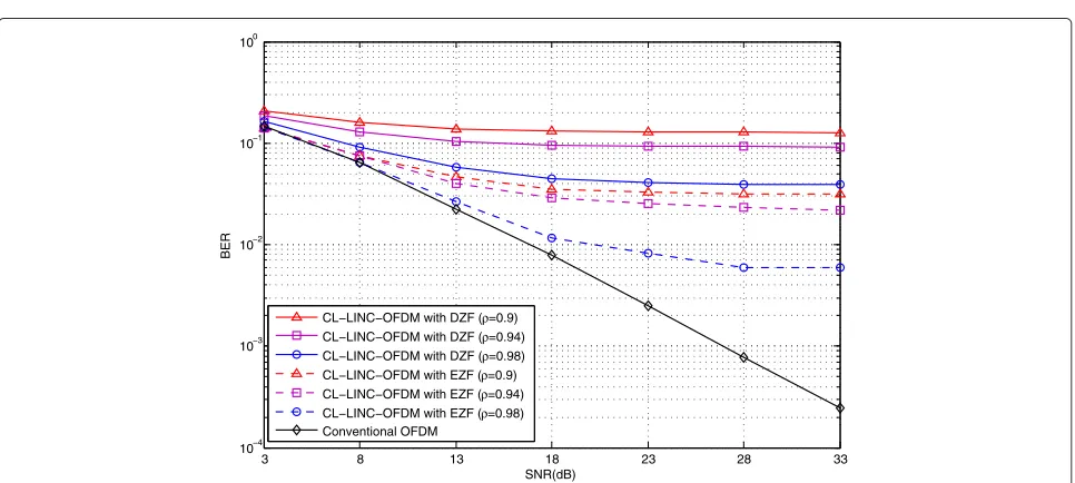
3 8 13 18 23 28 33
10−4 10−3 10−2 10−1 100
SNR(dB)
BER
CL−LINC−OFDM with DZF (ρ=0.9) CL−LINC−OFDM with DZF (ρ=0.94) CL−LINC−OFDM with DZF (ρ=0.98) CL−LINC−OFDM with EZF (ρ=0.9) CL−LINC−OFDM with EZF (ρ=0.94) CL−LINC−OFDM with EZF (ρ=0.98) Conventional OFDM
3 4 5 6 7 8 9 10 11 12 0
2 4 6 8 10 12 14 16 18
V20/Es(dB)
SINR(dB)
SNR=15dB
SNR=12dB
SNR=9dB SNR=18dB
SNR=6dB
Theoretical values
Simulated values o
Fig. 9Relationship of average SINR and PAPR in proposed CL-LINC-OFDM system
systems is then evaluated for PAPR being equal to 6, 8, and 10 dB, respectively. Table 1 shows the results calculated from (41) and (42). As we can see, the power efficiency of the CL-LINC-OFDM system is about four-time higher than that of the conventional OFDM system when the lin-ear PA in [35] is applied. Similar result is also observed in [25, 26]. The power efficiency of the CL-LINC-OFDM system becomes about seven-time higher than that of the conventional OFDM system when the nonlinear PA in [36] is applied. The power efficiency of the CL-LINC-OFDM system can be even higher when PAs with higher nonlinearity are considered [4].
6 Simulation results
In this section, we report simulation results demonstrat-ing the effectiveness of the proposed approaches. Table 2 gives the detailed simulation parameters.
We first evaluate the validity of the derived interference variance in (22) when the EZF is applied. Without loss of generality, we letEs=1. Figure 6 shows the simulated and the theoreticalσv2for variousV02/Es’s. As we can see, the calculated values in (22) are close to the simulated results and the approximation error can be ignored.
We then evaluate the performance of the CL-LINC-OFDM system with the proposed EZF equalizer. A
0 5 10 15
10−6 10−5 10−4 10−3 10−2 10−1 100
SNR(dB)
BER
CL−LINC−OFDM with DZF+VA CL−LINC−OFDM with EZF+VA CL−LINC−OFDM with EZF+LVA(L=4) CL−LINC−OFDM with EZF+LVA(L=8) Conventional OFDM
0 5 10 15 10−6
10−5 10−4 10−3 10−2 10−1 100
SNR(dB)
BER
CL−LINC−OFDM with DZF+VA CL−LINC−OFDM with EZF+VA CL−LINC−OFDM with EZF+LVA(L=4) CL−LINC−OFDM with EZF+LVA(L=8) Conventional OFDM
Fig. 11Performance comparison of conventional coded OFDM system and proposed coded CL-LINC-OFDM system (ρ=0.96)
channel model characterized by the antenna correlation is used in the simulations. Lethp=h1,p h2,pTbe the vec-tor consisting of the twopth taps of two channels. Denote its correlation matrix asRp. Then,
Rp=E +
hphHp ,
=Pp %
1 ρ
ρ 1
&
, (43)
where Pp is the power of the pth tap and ρ is the correlation coefficient. WithRp, we can generate the cor-related MIMO channels. For details, see [37]. SinceTX1
andTX2are located closely, the two channel responses are
highly correlated, which meansρ is close to one. When
ρ =1,H1andH2are fully correlated, i.e.,H1 = H2and
the CL-LINC-OFDM system will be reduced to a conven-tional OFDM system.H1andH2are assumed to be known
and the average SINR is used as the performance mea-sure. Also, letEs/σn2 = 20 dB and PAPR = 10 dB. With this PAPR setting, the effect of the clipping noise can be neglected. For the conventional DZF equalizer, we have the average SINR, denoted by SINRDZF, as
0 5 10 15
10−6 10−5 10−4 10−3 10−2 10−1 100
SNR(dB)
BER
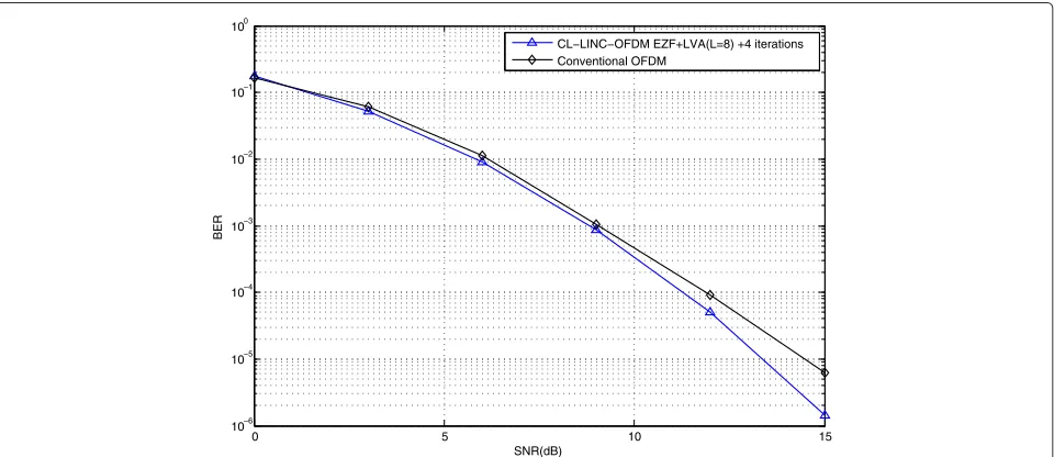
CL−LINC−OFDM EZF+LVA(L=8) +4 iterations Conventional OFDM
SINRDZF=
E (
H1+H2 2
)
s2
!
E y−
(
H1+H2 2
)
s2
!. (44)
For the EZF equalizer, we have the average SINR, denoted by SINREZF, as
SINREZF=
E (H1+H2
2 +jμ
H1−H2
2
)
s2
!
E y−(H1+H2
2 +jμ
H1−H2 2
)
s2
!. (45)
We evaluate the SINRs corresponding to different antenna correlations; Fig. 7 shows the simulation result. From the figure, we can see that the SINR is strongly affected by the antenna correlation. The smaller the cor-relation, the lower the SINR. For the DZF equalizer, the SINR is reduced from 16 to 4 dB when the correlation varies from 0.995 to 0.9. For the EZF equalizer, the SINR is reduced from 20 to 10.5 dB. As we can see, the EZF equalizer is much better than the DZF. Figure 8 shows the bit-error-rate (BER) simulations for various antenna cor-relations. As we can see, the EZF equalizer significantly outperforms the DZF equalizer. From Fig. 8, we can also see that the performance of the CL-LINC-OFDM is much worse than that of the conventional OFDM, especially when the antenna correlation is lower.
As we mentioned in the second section, the interference power depends on the value ofV0, i.e, the PAPR value. A
smallerV0will result in a smaller interference level but a
larger clipping noise level. Thus, there is an optimumV0,
i.e., an optimum clipping ratio. Simulations are then used to find the value. Figure 9 shows the relationship between SINR and PAPR when the EZF equalization is applied for
ρ = 0.98. Note that the theoretical SINR derived in (34) is also shown. From Fig. 9, we can see that for higher SNR (for example, 15 dB), the optimum PAPR is between 6 and 7 dB. This result indicates that when PAPR is higher than 7 dB, the interference dominates the SINR, and when it is smaller than 6 dB, the clipping noise dominates. It can also be seen that the theoretical SINR is close to the simulated SINR.
From Fig. 9, we can also see that when input SNR is lower, the optimum clipping ratio tends to be higher. How-ever, the variation of the resultant equalized SINR is small. It is then proper to let the optimum clipping ratio be 6 dB for all cases.
Now, we consider the proposed coded CL-LINC-OFDM system. We use a simple (2,1,2) CC encoder with the gen-erator polynomials given by g(1) = 1 + D+ D2 and
g(2) = 1+D2. For simplicity, we let the size of the
cod-ing block be 126. Then, the size of the coded output block will be 2×(126+2)=256 where the two additional bits are for tail bits. Without any puncturing, we can then fit
each coded block into one QPSK OFDM symbol with size ofM = 128. Also let the interleaver be a 16×16 block interleaver.
We now compare the performance of the conventional coded OFDM and the proposed coded CL-LINC-OFDM systems. For the both systems, the PAPR is set as 6 dB. The standard VA is used for the decoding scheme of the con-ventional OFDM while the proposed ML detector with the EZF equalizer is used for the proposed coded OFDM system. The performance of the CL-LINC-OFDM system with conventional VA and DZF is also evaluated. Here, we use the performance of the conven-tional coded OFDM system as a benchmark. Figures 10 and 11 show the simulation results for ρ = 0.98 and
ρ = 0.96, respectively. Similar to the previous case, the performance of the combinerless system degrades as theρ is reduced. However, the level of the degradation is not as severe as that in the uncoded case. From Figs. 10 and 11, we can see that when the proposed ML detector is applied, the performance of CL-LINC-OFDM can be enhanced even for L = 4 in the LVA. Note that in some cases, the performance of the CL-LINC-OFDM is even better than the conventional OFDM. This is because the LINC operation can be viewed as a coding process; it acts as an inner code added for the system. With the inner code, the performance of CL-LINC-OFDM can outperform con-ventional OFDM. Figure 12 shows the simulation result when the IC scheme proposed in fourth section is applied. We let the number of iterations be three andξibe the can-cellation factor in theith iteration. With simulations, we derive thatξ1 = 0.2,ξ2 = 0.4, andξ3 = 0.8. From the
figure, we can see that CL-LINC-OFDM significantly out-performs conventional OFDM when SNR is higher (e.g., 15 dB). Note that we letρ = 0.96 in the simulation case, implying that the performance gap will be even larger for
ρ=0.98.
7 Conclusions
to provide soft outputs. How to use the soft outputs to obtain the ML solution deserves further investigations. As mentioned, the LINC operation can be seen as a cod-ing process. How to calculate its soft outputs and apply sophisticate iterative decoding schemes can also serve potential topics for further research. Finally, a bandwidth problem needs to be considered for real-world applica-tions. It is known that the bandwidth of the LINC compo-nent signals is much wider than its original signal. There are a number of methods to reduce the bandwidth, e.g., [38, 39]. However, these methods may distort the com-bined signal. How to recover the transmit signal at the receiver deserves further investigations. Research in these directions is now underway.
Competing interests
The authors declare that they have no competing interests.
Author details
1Institute of Communications Engineering, National Chiao Tung University, University Road, 30010 Hsinchu, Taiwan.2Mediatek Inc., Dusing 1st Rd, 30078 Hsinchu, Taiwan.
Received: 24 November 2015 Accepted: 14 June 2016
References
1. R van Nee, R Prasad,OFDM for Wireless Multimedia Communications, 1st edn. (Artech House, Boston, MA, 2000)
2. P Wang, Y Li, L Song, B Vucetic, Multi-gigabit millimeter wave wireless communications for 5G: from fixed access to cellular networks. IEEE Commun Mag.53(1), 168–178 (2015)
3. L Li, X Niu, L Chen, Y Chai, T Zhang, J Shi,et al, Design of 60GHz RF transceiver in CMOS: challenges and recent advances. China Commun. 11(6), 32–41 (2014)
4. R Bhat, A Chakrabarti, H Krishnaswamy, inIEEE MTT-s IMaRC 2014. Advances in th Design of Efficient-yet-Linear Watt-Class mmWave CMOS, (Bangalore, India, 2014), pp. 53–56
5. J Armstrong, Peak-to-average power reduction for OFDM by repeated clipping and frequency domain filtering. Electronics Lett.38(5), 246–247 (2002)
6. X Zhu, W Pan, H Li, Y Tang, Simplified approach to optimized iterative clipping and filtering for PAPR reduction of OFDM signals. IEEE Trans Commun.61(5), 1891–1901 (2013)
7. SH Muller, JB Huber, OFDM with reduced peak-to-average power ratio by optimum combination of partial transmit sequences. Electronics Lett. 33(5), 368–369 (1997)
8. L Li, D Qu, T Jiang, Partition optimization in LDPC-Coded OFDM systems with PTS PAPR reduction. IEEE Trans Veh Tech.63(8), 4108–4113 (2014) 9. AE Jones, TA Wilkinson, SK Barton, Block coding scheme for reduction of
peak to mean envelope power ratio of multicarrier transmission schemes. Electronics Lett.30(25), 2098–2099 (1994)
10. RW Bauml, RFH Fischer, JB Huber, Reducing the peak-to-average power ratio of multicarrier modulation by selected mapping. Electronics Lett. 32(22), 2056–2057 (1996)
11. FH Raab, P Asbeck, S Cripps, PB Kenington, ZB Popovic, N Pothecary,et al, Power amplifiers and transmitters for RF and microwave. IEEE Trans Microw Theory Tech.50(3), 814–826 (2002)
12. LR Kahn, Single-sideband transmission by envelope elimination and restoration. Proc IRE.40(7), 803–806 (1952)
13. C Buoli, A Abbiati, D Riccardi, inProc. 25th European Microwave Conf. Microwave power amplifier with “envelope controlled” drain power supply, (Bologna, Italy, 1995), pp. 31–35
14. WH Doherty, A new high-efficiency power amplifier for modulated waves. Proc IRE.15(3), 469–475 (1936)
15. J Groe, Polar transmitters for wireless communications. IEEE Commun Mag.45(9), 58–63 (2007)
16. P Liang, H Wang, CH Peng, A Peng, HC Hwang, G Chien,et al, Digital transmitter design for mobile devices. IEEE Commun Mag.51(10), 114–123 (2013)
17. DC Cox, Linear amplification with nonlinear components. IEEE Trans Commun.22(12), 1942–1945 (1974)
18. H Chireix, High power outphasing modulation. Proc IRE.23(11), 1370–1392 (1935)
19. A Bateman, JP McGeehan, LINC transmitter. Electronics Lett.27(10), 844–846 (1991)
20. X Zhang, LE Larson, PM Asbeck, P Nanawa, Gain/phase
imbalance-minimization techniques for LINC transmitters. IEEE Trans Microw. Theory Tech.49(12), 2507–2516 (2001)
21. L Sundstrom, Automatic adjustment of gain and phase imbalances in LINC transmitters. Electronics Lett.31(3), 155–156 (1995)
22. A Birafane, M El-Asmar, AB Kouki, M Helaoui, FM Ghannouchi, Analyzing LINC systems. IEEE Microwave Mag.11(5), 59–71 (2010)
23. KY Jheng, YJ Chen, AY Wu, Multilevel LINC system designs for power efficiency enhancement of transmitters. IEEE J Sel Top Signal Process.3(3), 523–532 (2009)
24. FH Raab, Efficiency of outphasing RF power-amplifier systems. IEEE Trans Commun.33(10), 1094–1099 (1985)
25. MA Elaal,LINC Based Amplifier Architectures for Power Efficient Wireless Transmitters. (Dept. Elect. Eng., Ecole Polytechnique De Montreal, Montreal, Canada, 2009)
26. F Benahmed Daho, G Neveux, M Mouhamadou, P Vaudon, C Decroze, D Carsenat,An operational modified-LINC demonstrator for wireless communication, (Rome, Italy, 2011), pp. 480–482
27. S Ali, B Adebisi, G Markarian, E Arikan, Signal combining in LINC amplifier using Alamouti codes. Electronics Lett.46(18), 1301–1302 (2010) 28. C Liang, B Razavi, Transmitter linearization by beamforming. IEEE J
Solid-State Circ.46(9), 1956–1969 (2011)
29. SL Cheng, WR Wu, YP Hsu,An enhanced zero-forcing equalizer for combinerless LINC-OFDM systems, (Washington DC, USA, 2014), pp. 795–799
30. KS Hsu, inMaster thesis. Maximum likelihood detection for combinerless LINC-OFDM systems (Inst. Commun. Eng., Nat. Chiao Tung Univ., Hsinchu, Taiwan, Republic of China, 2011)
31. F Tosato, P Bisaglia, inProc. IEEE ICC 2002. Simplified soft-output demapper for binary interleaved COFDM with application to HIPERLAN/2, (New York, USA, 2002), pp. 664–668
32. H Ochiai, H Imai, Performance analysis of deliberately clipped OFDM signals. IEEE Trans. Commun.50(1), 89–101 (2002)
33. N Seshadri, CEW Sundberg, List Viterbi decoding algorithms with applications. ITrans, EEE, Commun.42(234), 313–323 (1994) 34. L Bahl, J Cocke, F Jelinek, J Raviv, Optimal decoding of linear codes for
minimizing symbol error rate (Corresp.) IEEE Trans. Inform.20(2), 284–287 (1974)
35. CW Tseng, YJ Wang, A 60 GHz 19.6 dBm power amplifier with 18.3 % PAE in 40 nm CMOS. IEEE Microwave Wireless Components Lett.25(2), 121-123 (2015)
36. D Zhao, P Reynaert, A 60-GHz dual-mode class AB power amplifier in 40-nm CMOS. IEEE J. Solid-State Circ.48(10), 2323–2337 (2013) 37. JP Kermoal, L Schumacher, PE Mogensen, Channel Characterization.
IST-2000-30148 I-METRA-WP2-D2 (2002). http://www2.elo.utfsm.cl/~ ipd465/Papers%20y%20apuntes%20varios/ISTinfo2000.pdf
38. AK Mustafa, S Ahmed, M Faulkner, Bandwidth limitation for the constant envelope components of an OFDM signal in a LINC architecture. IEEE Trans Circ. Syst I, Reg Papers.60(9), 2502–2510 (2013)