R E S E A R C H
Open Access
Efficient transceiver design for large-scale
antenna systems
Joonwoo Shin
Abstract
We present linear transceiver design strategies for large-scale multiple-input multiple-output downlink systems when the user nodes have multiple receive antennas, and they receive multiple streams. First, we propose a
matched-filtering-based optimal power allocation method using the sum-rate maximization criterion and utilizing the favorable propagationproperty of large-scale antenna systems. In uncorrelated transmit antennas, we observe that the effective channel can be represented by the receive antenna correlation matrix. Motivated by this observation, we also propose a suboptimal two-step power allocation method in which each user node is equipped with two receive antennas to reduce the computational complexity of the optimum power allocation method. Compared with the optimum power allocation method, the proposed two-step method reduces the dimensions of the bisection search space while achieving essentially the same level of sum rate.
Keywords: Large-scale antenna systems; Multiple-input multiple-output (MIMO); Power allocation; Sum-rate maximization
1 Introduction
Large-scale antenna or massive input multiple-output (MIMO) system, a system defined as a large num-ber of antenna-equipped base station (BS) while serving a large number of users simultaneously has been identi-fied as a promising air interface technology [1-3]. A salient feature of large-scale antenna systems is that, when the number of BS antennas grows large, the random channel vectors between the users and the BS become pairwisely orthogonal [4]. Therefore, in the limit of infinite num-ber of antennas, with simple linear processing approaches such as a matched filter precoder, inter-user interferences (IUI) disappear completely [5]. The IUI elimination fea-ture of large-scale antenna systems has sparked a flurry of research activities aimed at understanding the signal processing, information theoretic ramifications, and real-istic channel behavior of massive MIMO sytems [1-4,6-8]. In [1,6], large-scale antenna systems are reviewed from various perspectives including antenna and propagation aspects, transceiver design, and fundamental information theoretic gains. A follow-up tutorial [2,3] briefly discussed recent works. To the best of our knowledge, most of works
Correspondence: [email protected]
Division of Navigation Science, Korea Maritime and Ocean University (KMOU), Dongsam-dong, Youngdo-gu, 606-791 Busan, Republic of Korea
on the large-scale antenna systems assume that user ter-minals are equipped with a single receive antenna[1,5,9].
In this paper, we aim to design transceivers for the large-scale antenna system where multiple streams are designated for user terminals with multiple receive anten-nas. Here, we assume that the number of BS antennas exceeds the total number of antennas of users. Inspired by the fact that in large-scale antenna systems a simple matched-filtering precoder can eliminate the IUI effec-tively [1,5], we adopt conjugate beamforming as the first part of the precoder. After that, a sum-rate maximizing processing is appended. We observe that when the spacing between transmit antennas is sufficiently large, sum-rate maximizing transceivers can be obtained with the receiver correlation matrices. Motivated by this observation, when each terminal has two receive antennas, we propose a suboptimal two-step power allocation method. In general, the search space dimension of the optimal power allo-cation algorithm is proportional to the number of users and the number of streams per user. With the proposed two-step power allocation method, the search space size is only proportional to the number of users. Through numerical simulations, we verify that the sum-rate per-formance of the proposed methods outperform the equal power allocation method. In addition, we demonstrate the
effectiveness of the proposed two-step power allocation method.
The following notations are used. We employ uppercase boldface letters for matrices and lowercase boldface let-ters for vectors. For any general matrixX,XT,XH, Tr(X), SVD(X), and [X]i,jdenote the transpose, Hermitian trans-pose, trace, singular value decomposition, and the(i,j)-th element ofX, respectively. An identity matrix of sizenis denoted byIn.
2 System model and preliminaries 2.1 MU-MIMO system model
We consider the time-division-duplexing (TDD) down-link single-cell MU-MIMO systems. The system includes one base station with Nt transmit antennas that trans-mits data streams toKuser nodes. Each user terminal has multiple receive antennas. Without loss of generality, we assume that each user node hasNrreceive antennas. Fur-thermore, from the TDD channel reciprocity between the downlink and uplink, we assume that the downlink chan-nel state information is known to the transmit side; and due to the single-cell assumption, we do not consider the pilot contamination problems [10]. The information sig-nal vector for thek-th user node is denoted bysk∈CNr×1 and its power is normalized asE(sksHk) = INr. The
sig-nalsk is linearly precoded by the precoding matrixTk ∈ CNt×Nr. The precoded signal vectorx
k =Tksk, 1≤k≤K is transmitted to thek-th user node from the base station. Then, the received signal vector at thek-th user node can be represented by station to thek-th user node andnk equals the additive white Gaussian noise (AWGN) vector with zero mean and
E[nknHk]= σn2INr. The parametergk models the
geomet-ric attenuation and shadow fading, which is assumed to be independent over transmit antenna and to be constant over many coherence time intervals.
To introduce the channel correlation, the Kronecker model is adopted to describeHkas [11]:
Hk =R1rk/2HwkR
1/2
tk
whereRrk ∈CNr×NrandRtk ∈CNt×Ntare the receive
cor-relation matrix and the transmit corcor-relation matrix of the
k-th user node, respectively. The(i,j)-th elements ofRrk
linear array antenna sets. When antenna spacing at the transmit side is sufficiently large, we can assume that the columns ofHk are independenta, i.e.,Rtk = INt,∀k. On
the other hand, the receive antennas of the user termi-nal are closely spaced due to the size limitation of the user terminal. Therefore, we assume that the rows ofHk’s are correlated, i.e.,Rrk = INr,∀k. The elements ofHwk
are circularly symmetric complex Gaussian random vari-ables with zero mean and unit variance, and they have an independent and identically distribution. Then, the user node combines its received signal with decoding matrix Dk ∈CNr×Nr to decode the desired signals:
2.2 Review of results on the large-scale MIMO systems
Lemma 1.Let a,b ∈ CNt×1 be two independent
vec-where a=.s. denotes the almost sure convergence. Lemma 1 is called thefavorable propagation(FP) property of large-scale antenna systems [1].
Due to lemma 1, a matched-filtering precoder is popu-larly adopted for the large-scale MIMO precoding method due to its computational efficiency and rate achievabil-ity [1,5]. We assumeTk = N1tH
H
kMk and the precoding matrixMk ∈ CNr×Nr after matched-filtering. Then, the decoded signalsˆkcan be rewritten as
ˆ
Different from the case for when user terminals are equipped with single receive antenna, the power normal-ization factor is not included in Equation 3. Instead, the precoding matricesMk’s are designed to satisfy the trans-mit power constraint,Kk=1Tr(TkTHk)≤Pt, andPtis the maximum transmission power of base station.
3 Sum-rate maximizing transceiver design
According to lemma 1, whenNt→ ∞, we have
(Equation 4) fairly well [7]. Then, we have the decoded signal being free of inter-user interference as follows:
ˆ
sk ∼=√gkDkRrkMksk+Dknk (5)
Here, we observe that the remaining sum-rate maximiz-ing processmaximiz-ing{Dk}and{Mk}can be found by considering receive antenna correlation matrix {Rrk}. From channel
diagonalization SVD(Rrk) = VkkVHk, we have Mk = Vkk1/2andDk = VHk, wherek ∈ RNr×Nr is the power loading diagonal matrix. The information rateb for the
k-th user node can be represented as
Rk =log
The sum-rate maximizing power allocation matrices ks are calculated by solving the following optimization problem,
The power constraint of Equation 7 is the average power constraint that is obtained by
The solution of the problem (Equation 7) is the well-known water-filling solution that requires numeri-cal bisection search [12]. Finally, we find the sum-rate maximizing transceivers for large-scale antenna systems T(opt)k =HHkVkk1,opt/2 andDk=VHk, ∀k.
4 Two-step power allocation
The proposed optimum precoder in Section 33 requires a bisection search to optimally allocate the transmit power. In this section, we propose a computationally efficient power allocation method when each user node has two receive antennasc, i.e.,Nr=2.
To derive the two-step power allocation method, we temporarily assume a high SNR regime in which the equal power allocation k = γkINr for all k is the optimum
and there is no receive antenna correlation, i.e.,ρrk = 0
or k = INr for all k. Then, the optimization problem
(Equation 7) can be represented as
max
where the power constraint is obtained by
kTr(kk) = kTr(γkINr) =
kNrγk. The power loading parameters{γk}can be found by the water-filling algorithm. Note that compared with the optimum power allocation calculation (Equation 7), the search space of Equation 8 is reduced toK fromKNr. Through the first step, we find the amount of per user power allocation.
Now, with per user power constraint{ˆpk}wherepˆk =
Nrγk, the optimization problem (Equation 7) is divided intoKsubproblems. Thek-th subproblem is represented by
Optimization problem (Equation 9) determines the amount of power allocation to each stream, which is designated to thek-th user node.
Lemma 2.For2×2correlation matrixR=[ 1, ρ;ρ, 1]
(0≤ρ≤1), eigenvalues ofRare1+ρand1−ρ.
Proof 1.From det(R−λI)= 0, we knowλ =1−ρor
1+ρ.
According to Lemma 2 and the observation that the effective channel of Equation 5 is the receive antenna cor-relation matrixRrk, we have the singular value matrix of
Rrk ask =[ 1+ρrk, 0; 0, 1−ρrk] when each user node
has two receive antennas. Replacingkin Equation 9 with [ 1+ρrk, 0; 0, 1 −ρrk], we can derive the closed form
Table 1 Simulation parameters
Cell radius 1 km
Bandwidth 20 MHz
Number of userK 20
Number of BS antennaNt 40∼200
Number of user terminal antennaNr 2
Maximum transmission power 32 dBm
Distance-dependent path loss 128.1+37.6 log (r) dB,rkilometers
Receiver noise density −101 dBm/Hz
Noise figure 5 dB
Algorithm 1Two-step power allocation
Step 1: Applying water-filling algorithm to Equation 8, find{γk}
Step 2: Calculate the per user based power allocation ˆ
pk=Nrγkfor allk
Step 3: Calculate the per stream based power allocation ˆ
k =diag(γk,1,γk,2)with Equations 10 and 11.
Step 4: Repeat step 2 to find the amount of power allocation over allKuser data streams.
The proposed two-step power allocation method is summarized in Algorithm 1. The resultant two-step pre-coders are represented asT(ts)k =HHkVkˆ1k/2, ∀k. With the proposed two-step method, we can reduce the dimensions of the search space fromKNrtoK.
Note that the generalization of the second step to more than two receive antennas (Nr > 2) is straightforward. Instead of closed form solutions, however, it requires numerical search in Step 3 of Algorithm 1 as follows.
Step 3 : Applying water-filling algorithm to Equation 9, calculate the per stream based power allocationˆk.
5 Simulation results
For the simulation of the sum-rate performance, we set
K = 20,Nt = 40 ∼ 200,Nr = 2, andρrk = 0 and 0.5
for allk. Table 1 gives the simulation parameters. The cell radius is 1 km. For the consistency of the simulation, the location of each user is randomly selected from uniform distributionU(0, 1)and is kept fixed over simulation runs. The distance-dependent path loss is 128.1+37.6 log(r)
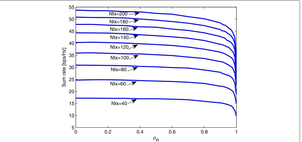
dB (rkilometers). The maximum transmission power is set to 32 dBmd. The receiver noise density is set to−101 dBm/Hz, and the noise figure is 5 dB. The results are averaged over 1,000 independent trials. Figure 1 shows the average sum-rate performance of the optimum power allocation method over the receive antenna correlation ρrk ∈[ 0, 0.9999] for allk. We observe that as the receive
antenna correlation increases, the sum-rate performance decreases. Specifically, withNt = 200, when receive cor-relation is less than or equal to 0.9, the sum rate drops less than 10%. However, whenρrk = 0.99 andρrk = 0.9999,
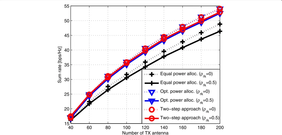
the sum rates drop 21% and 37%, respectively. Figure 2 shows the average sum-rate performance of the optimum power allocation method in Section 33 and the proposed two-step method in Section 44. For comparison, we plot
40 60 80 100 120 140 160 180 200
15 20 25 30 35 40 45 50 55
Number of TX antenna
Sum rate [bps/Hz]
Equal power alloc. (ρrk=0)
Equal power alloc. (ρrk=0.5)
Opt. power alloc. (ρrk=0)
Opt. power alloc. (ρrk=0.5)
Two−step approach (ρrk=0)
Two−step approach (ρrk=0.5)
0 0.2 0.4 0.6 0.8 1 5
10 15 20 25 30 35 40 45 50 55
ρR
Sum rate [bps/Hz]
Ntx=200
Ntx=180 Ntx=160
Ntx=140
Ntx=120
Ntx=100
Ntx=60 Ntx=80
Ntx=40
Figure 2The sum-rate performances whenK=20,Nt=40∼200,Nr=2, andρrk=0and0.5for allk.
the equal power allocation method in which the precoder is represented asTeqk =√αHHkVkfor allk,α =Pt/KNr. Note that the proposed two-step method achieves the optimum sum-rate performance while it can be imple-mented with low complexity by reducing the search space. In addition, we verify that both proposed methods outper-form the equal power allocation method.
6 Conclusion
In this paper, we have proposed a MU-MIMO transceiver design method for large-scale antenna systems using the sum-rate maximization criterion when each user node is equipped with multiple receive antennas. Inspired by the favorable propagation characteristics of the large-scale antenna systems, we have proposed a matched-filtering-based optimal transceiver design method that maximizes the sum rate. In addition, we have proposed a suboptimal two-step power allocation method with low computa-tional complexity by reducing the dimension of the bisec-tion search space from KNr to K. Through the simula-tion results, the effectiveness of the proposed transceiver design methods have been validated.
Endnotes
aThis assumption is reasonable because in general the
transmit antennas at base station of the large-scale MIMO systems can be deployed to have a large separation among them.
bThis is anapproximateresult assumingN t→ ∞ cNote that current specification of mobile wireless
communications supports mobile terminals with two receive antennas [13]
dConsidering the power saving effect of large-scale
MIMO systems [1], we choose much less transmission power than the ordinary base station transmission power, 43 [dBm]
Appendix
Usingβk gkσn−2, andk=diag(γk,1,γk,2), the
optimiza-tion problem (Equaoptimiza-tion 9) can be rewritten as
arg{γk,1,γk,2}max log1+βk(1+ρrk)
2γ
k,1
+log1+βk(1−ρrk)
2γ
k,2
(6.1) subject to(1+ρrk)γk,1+(1−ρrk)γk,2≤ ˆpk
Because there are no inter-stream interferences, the optimum power allocation should satisfy the equality con-straint,(1+ρrk)γk,1+(1−ρrk)γk,2 = ˆpk. Then, we have
γk,2= ˆ
pk−(1+ρrk)γk,1
(1−ρrk)
(6.2)
Since this is a convex optimization problem overγk,1,
from the Karush-Kuhn-Tucker (KKT) condition [14], the optimum valueγk,1is obtained as
γ(opt)
k,1 =
βk(1−ρrk)(1+ρrk)2pˆk+4ρrk
2βk(1+ρrk)3(1−ρrk)
(6.3)
The parameterγk(opt),2 can be derived by replacingγk,1in
Competing interests
The authors declare that they have no competing interests.
Received: 6 November 2014 Accepted: 3 February 2015
References
1. F Rusek, D Persson, BK Lau, EG Larsson, TL Marzetta, O Edfors, F Tufvesson, Scaling up MIMO: opportunities and challenges with very large arrays. IEEE Signal Process. Mag.30, 40–60 (2013)
2. L Lu, GY Li, AL Swindlehurst, A Ashikhmin, R Zhang, An overview of massive MIMO: benefits and challenges. IEEE J. Select. Topics Signal Process.8, 742–758 (2014)
3. EG Larsson, O Edfors, F Tufvesson, TL Marzetta, Massive MIMO for next generation wireless systems. IEEE Commun. Mag.52, 186–195 (2014) 4. HQ Ngo, EG Larsson, TL Marzetta, Energy and spectral efficiency of very
large multiuser MIMO systems. IEEE Trans. Commun.8, 1436–1449 (2013) 5. TL Marzetta, Noncooperative cellular wireless with unlimited numbers of base station antennas. IEEE Trans. Wireless Commun.9, 3590–3600 (2010) 6. RC Lamare, Massive MIMO systems: Signal processing challenges and
research trends. ArXiv pre-print cs.IT/1310.7282. Available: http://arxiv. org/abs/1310.7282
7. T Wild, C Hoek, J Hoydis, ST Brink, inProc. IEEE Int. Symp. Wireless Commun. Systems (ISWCS, Paris). Channel measurements for large antenna arrays, (2012), pp. 811–815
8. X Gao, F Tufvesson, O Edfors, F Rusek, inProc. Asilomar Conf. Signals, Syst., Comput, Pacific Grove. Measured propagation characteristics for very large MIMO at 2.6 GHz, (2012), pp. 295–299
9. H Yang, TL Marzetta, Performance of conjugate and zero-forcing beamforming in large-scale antenna systems. IEEE J. Select. Areas Commun.31, 172–179 (2013)
10. J Jose, A Ashikhmin, TL Marzetta, S Vishwanath, Pilot contamination and precoding in multi-cell TDD systems. IEEE Trans. Wireless Commun.10, 2640–2651 (2011)
11. D Shiu, GJ Foschini, MJ Gans, JM Kahn, Fading correlation and its effect on the capacity of multielement antenna systems. IEEE Trans. Commun.48, 502–513 (2000)
12. TM Cover, JA Thomas,Elements of Information Theory. (Wiley, 111 River Street Hoboken, NJ, United States, 1991)
13. 3GPP TR 36.211 V 11.1.0 (Release 11): Evolved Universal Terrestrial Radio Access (E-UTRA) (2012). Available: http://www.etsi.org/deliver/etsi_ts/ 136200_136299/136211/11.01.00_60/ts_136211v110100p.pdf 14. S Boyd, L Vandenberghe,Convex Optimization. (Cambridge University
Press, University Printing House Shaftesbury Road, Cambridge, United Kingdom, 2004)
Submit your manuscript to a
journal and benefi t from:
7Convenient online submission 7Rigorous peer review
7Immediate publication on acceptance 7Open access: articles freely available online 7High visibility within the fi eld
7Retaining the copyright to your article