R E S E A R C H
Open Access
Joint cross-layer resource allocation and
interference avoidance with QoS support for
cognitive radio systems
Hailan Peng
*and Takeo Fujii
Abstract
In this article, we study the coexistence and optimization of a centralized orthogonal frequency-division multiple access-based multiuser cognitive radio (MCR) system which coexists with a cellular primary system (PS). Two different spectrum sharing methods, i.e., the spectrum underlay/overlay, are utilized for different coexistent frameworks, in which, the sharing method is adapted to one of them based on the distance between two base stations and the interference limit in the PS. We consider a PS-assistance-based coexistent architecture and propose a joint power control and interference management method to avoid unacceptable interference to primary users (PU). Firstly, the relationship between power limits at secondary users (SU) and interference margin at PUs can be obtained. Then, to provide the SUs with satisfactory quality of service (QoS), and optimize the sum rate of the MCR system as well, a constrained two-variable nonlinear optimization problem (OP) is formulated. We solve this OP by (i) simplifying the QoS constraints from medium access control-layer to physical-layer based on a cross-layer approximation; and (ii) using the Lagrangian duality based technique to solve the simplified OP, and iterative water-filling is implemented to find the optimal power and subcarrier allocation. Simulation results show that, compared to the conventional designs, our algorithm achieves significant higher throughput and can guarantee the required signal to interference plus noise ratio of the PUs and the QoS of the SUs well. Moreover, compared to the spectrum overlay sharing method, the spectrum underlay & overlay can provide substantial higher spectrum efficiency.
Keywords:multiuser cognitive radio, cross-layer design, orthogonal frequency-division multiple access (OFDMA), QoS, Lagrangian duality optimization
1 Introduction
Due to the rapid growth of wireless communications, the problem of spectrum shortage has become much severer. The report from the Federal Communications Commission (FCC) has shown that most of the licensed spectrum is currently under-utilized [1]. Cognitive radio (CR) is a promising technology that can alleviate the severe spectrum shortage problem by making it possible for secondary (unlicensed) users (SU) to share frequency bands with primary (licensed) users (PU) in some geo-graphical location [2,3]. The SUs equipped with CR can sense and learn their surrounding environment to find a
spectrum band for opportunistic communication using either spectrum overlay (non-active PU bands sharing) or spectrum underlay (whole PU bands sharing).
Even though the basic idea of CR is simple, the effi-cient design of CR systems imposes the new challenges compared to conventional wireless systems. In a CR sys-tem, the basic philosophy is to allow universal maximi-zation of the spectrum utilimaximi-zation, and the utilimaximi-zation by the SUs cannot degrade the service in a primary system (PS). To flexibly implement spectrum sharing between the PUs and the SUs and enhance the spectrum effi-ciency, a dynamic resource allocation (DRA) for multi-ple SUs is required. Therefore, the orthogonal frequency division multiple-access (OFDMA) technique is an attractive candidate for such a flexible multiuser CR sys-tem [4].
* Correspondence: [email protected]
Advanced Wireless Communication Research Center, The University of Electro-Communications, 1-5-1 Chofugaoka, Chofu-shi, Tokyo 182-8585, Japan
Various resource allocation (RA) methods have been developed for OFDM-based CR systems. In [5,6], the fair RA of subcarrier, bit, and power in physical layer (PHY) to maximize the system throughput while guar-anteeing the interference power limited is studied for OFDM-based CR systems. However, these algorithms cannot dynamically adjust their rate requirement to dif-ferent SUs. Moreover, in [6], the authors assume that the PS and the CR system are both OFDM-based sys-tems, where it is impractical that the PS always uses OFDM. Currently, to the best of authors’knowledge, there are few studies on quality of service (QoS) support in OFDMA-based CR systems. The QoS designs in [7,8] for CR systems only considered non-real-time applica-tions. Up to now, the study on the spectrum underlay sharing is also sparse. A non-active PU bands access based spectrum overlay sharing was considered in [9,10] for RA in OFDM-based CR systems.
Despite the above contributions, the coexistence and optimization of a multiuser cognitive radio (MCR) sys-tem taking into account the mutual interference (MI) [11], QoS support and the different spectrum sharing schemes still have not been well studied. Several techni-cal difficulties are involved. First, the CR-system/PS coexistence involves the MI (the SU-to-PU interference as well as the PU-to-SU interference), which is compu-tationally complex and inaccurate. Furthermore, this should be obtained using very limited information. The CR system has to maximize the sum rate of all SUs, and at the same time make sure the SU-to-PU interference at each PU receiver does not exceed a limit. Second, to account for the MI, limited transmit power and satisfac-tory QoS, a large number of constraints are involved in the optimization procedure. Simplified and fast update algorithms are needed.
For the CR-system/PS coexistence, we consider a novel infrastructure-based dynamic system architecture, in which the CR system can be either independent or overlapped with the PS cell. Moreover, a PS-assistance-based joint spectrum underlay/overlay method is pro-posed for the spectrum sharing and realtime SU-to-PU interference control. First, a primary base station (PBS) determines the interference limits that can be accepted at each PU receiver based on its target performance, such as predefined signal to interference plus noise ratio (SINR), system outage probability, and so on. Then, the PBS broadcasts the interference limits on its occupied subbands and pilot signals for SU-to-PU interference channel estimation. According to the interference limits and geographic location of the CR system, a cognitive base station (CBS) decides available spectrum resources in the CR system and utilizes adaptive power control [12,13] to limit the SU-to-PU interference.
For the DRA, we propose a Lagrangian duality-based optimization framework under transmit power and QoS constraints for downlink transmissions. Our considered scenario can be modeled as a constrained two-variable nonlinear optimization problem (OP). In order to solve the problem and achieve our objectives, we develop near-optimal and low-complexity approaches. Firstly, based on the transmit power of the CBS and the inter-ference limits of PU receivers, a joint power control and interference avoidance method has been analyzed to simplify the constraints and guarantee the performance in the PS with priority. Then, a cross-layer design and the Lagrangian dual problem method have been consid-ered to transform the QoS requirements in medium access control (MAC) layer to PHY-layer, so as to pro-vide QoS support for the SUs during each scheduling time. Finally, iterative water-filling (IWF) algorithm has been implemented to solve the near-optimal and low-complexity problem of the system. Then, three subpro-blems have been deduced to get the solutions.
The rest of this article is organized as follows. In Sec-tion 2, the system models and related assumpSec-tions are described, which include the system architecture, the wireless propagation model, and the interference signal of the SUs. In Section 3, the constraints and the con-strained nonlinear OP have been formulated. In Section 4, the joint cross-layer optimization is elaborately con-sidered. Simulation and numerical results have been shown in Section 5. The results show that the joint cross-layer design has significant improvement com-pared to two conventional designs. Comcom-pared to the spectrum overlay sharing, the spectrum underlay sharing can provide a substantial performance improvement due to the higher spectrum efficiency. Finally, conclusions are drawn in Section 6.
2 System model and interference of SUs
2.1 OFDMA-based MCR system
We consider an OFDMA-based MCR system with K
SUs, and a CBS as the controller to share the spectrum with a PS, which is also an infrastructure-based cellular system, with one PBS andNPUs.
In this article, we consider downlink transmissions in both the CR system and the PS at the same time. The whole spectrum, which is originally licensed to PUs, is divided into M subcarriers in the CR system. Active subbands allocated to the PUs and OFDM subcarriers of the SUs have been shown in Figure 1, where, the band-width of subbandnis denoted byBn, which is allocated to PUn, andΔfis the subcarrier spacing of the CR sys-tem. The time slot duration in the CR system is equal to one OFDM symbol periodTs and the subcarriers are modeled in discrete time with the time-varying gain. The set of the SUs, the PUs, the subcarriers and the
time slots are denoted by
K={1,. . .,K},N ={1,. . .,N},M={1,. . .,M}, and
T ={1,. . .,T}, respectively.
2.2 PHY and propagation model
For all the links in the MCR system, the channels are subject to frequency selective fading. The channel gain is given by:
Gk,m,t=gk,m,t·μ(dk/d0)−α, ∀k∈K, ∀m∈M, ∀t∈T (1)
where √gk,m,t is the small-scale fading being modeled
as a Rayleigh distribution. μis the free-space factor of the channel gain, which can be calculated from
μ=Gs
λ
4πd0
2
, where, Gs denotes the transmit and
receive antenna gain, lis the wave length,d0is a refer-ence distance, set to bed0 = 10 m [14].dkdenotes the distance between the CBS and SU k.a is the path loss exponent. For any link, the power gainsGk,m,tare inde-pendent identical distribution (i.i.d.) random variables. Furthermore, we assume that the channel is block
fading, i.e.,gk,m,tis fixed during each time slot, which is much longer than the total duration of information col-lecting and reporting.
2.3 Interference to SUs
In the coexistent system, we consider two kinds of MI: the interference from the PBS to SUs and that from the CBS to PUs. The first interference is discussed here. The second one will be introduced in Section 3.1.
In the CR system, we assume that the interference from primary transmitters to SUs can be measured properly. Therefore, after the interference limits and the pilot signals from the PBS were collected, the channel information between two systems can be known at the CBS.
According to Figure 1, the interference power gener-ated by primary transmitters (i.e., the PBS on downlink, or PUs on uplink) to SUkat subcarriermand time slot
tcan be given by
Ik,m,t=
⎧ ⎪ ⎪ ⎪ ⎪ ⎨ ⎪ ⎪ ⎪ ⎪ ⎩
P(pd)G ps k,m,t
mf
(m−1)f
p(f)df, if downlinks in the PS
N n=1P
(u)
n Gnk,m,t mf
(m−1)f
n(f)df, if uplinks in the PS
(2)
where, P(pd) is the downlink transmit power at the
PBS, Gpsk,m,t is the power gain from the PBS to SU k,Fp (f) is the equivalent baseband power spectral density (PSD) of the PBS signal when the transmit power is nor-malized to one watt. P(nu) is the uplink transmit power
at PU n, Gnk,m,t is the power gain from PU nto SU k, Fn(f) is the normalized equivalent baseband PSD of the PUnsignal.
We now make further assumptions about channel gain information. We assume that the transmit power and PSDFp(f) andFn(f) are known to SUs, based on these, the SUs can estimate the mean channel gains from the primary transmitters to themselves. Due to the recipro-cal characteristic of the wireless channel, the mean channel gains from the SUs to the primary transmitters would be equal to these values. Similarly, the mean channel gains from the CBS to primary transmitters also can be estimated.
3 Constraints and problem definition
3.1 Power limits for SUs
In this article, we use a predefined SINR valuegpand an interference violation probabilityδ(p)together as the pri-mary target matrix. First, the received SINR at each PU must be no less than the predefined value gp. Let gn,t denote the SINR experienced by PU n at subband n. Therefore, we must have:
γn,t=
which is frequency selective over subband n. N0 is the complex Gaussian noise power.Inis the SU-to-PU inter-ference from the CBS to PU n. According to (3), the interference limit Imax
n of PU ncan be obtained as
fol-limits at the PUs.
Assume thatBnis a multiple ofΔf, which is from fre-quencyfn to frequencyfn+Bn, as shown in Figure 1. Let
xbe the beginning subcarrier index of subband n, sofn = (x-1)Δf. The SU-to-PU interferenceIn, which should be no larger than the interference limit Imax
n , can be
where, Sis the total secondary subcarrier number by which PU subbandn is affected,Pk,m,tis the allocated transmit power from the CBS to SU kon subcarrierm
and time slott, Gspn,m,t is the channel gain from the CBS
to PU n on subcarrier m. Fs(f) is the normalized
equivalent baseband PSD of the secondary OFDM sig-nal. Here, we only consider the main lobe power of the OFDM signal, because the interference power caused by the side lobes of the OFDM signal is very low, only 4.922% of the transmit power without multiplying the path loss [11]. Hence, we can assume
Pk,m,t
mf
(m−1)f
s(f)df≈Pk,m,t for simplicity. Moreover,
as long as the interference power on any subcarrier m
has been controlled no larger than the average limit
Imaxn /S, the predefined SINR at each PU can be guaran-teed. Let Ilim
m =Imaxn /S denote the interference limit for
subcarrierm. Therefore, Equation (5) can be rewritten as:
Im=Pk,m,tGspn,m,t≤Ilimm (6)
where, {Ilim
m = (Inmax/S)+,n∈N,m∈M} is a mapping
of the interference limits from primary subbandn toS
secondary subcarriers, where, (x)+= max(0,x).
In the CR-system, the adaptive power control is used to manage the interference from the CBS to PUs. Since the instantaneous interference level Inmay exceed the tolerable limit Imax
n , and violate the absolute interference
constraint, we define the interference violation probabil-ity as Pr{In>Imaxn }, where,Pr{A} denotes the
probabil-ity of event A, which should be no larger than the value δ(p)
. Therefore, considering the simplification from (5) to (6), there is a constraint on the interference violation probabilityδ(p)as following:
Pr{Pk,m,tGspn,m,t>Ilimm } ≤δ(p), ∀m∈M (7)
and PU non subcarrier m, and has been characterized as a Rayleigh distribution with the probability density
function (PDF) f(x;σ) = x
From (7), we have the following proposition for power control at the CBS.
where F-1(.) is the inverse function of the CDF of the Rayleigh distribution. Assume that location information of the PUs is available to the CBS where a RA algorithm is executed. A variety of location-awareness techniques are introduced in [15] and the references therein. The location-based primary protection and RA methods can be found in [16,17]. However, the methods proposed in [16,17] cannot guarantee the QoS for each SU, and they ignored the small-scale fading totally.
Proof:Details are provided in Appendix 1.
Then, the interference constraint (6) for PUs can be replaced by the following power limit for SUs:
Pk,m,t≤Pmmax,t , ∀m∈M (9)
where, Pmax
m,t is the maximum power that can be
allo-cated to subcarrierm. This power-limited access control method is based on the assumptions and system models in this article.
3.2 QoS constraints for SUs
At MAC layer, a cross-layer RA algorithm is proposed to support both real-time (RT) and non-real-time (NRT) services in the CR system. Assume that the first iusers fromK are with RT service, denoted by I ={1,. . .,i}; and the otherK-i users are with NRT service, denoted by J ={i+ 1,. . .,K}.
Real-time service is the services such as MPEG or streaming video or audio. It provides guarantees on throughput and latency, that is, each packet, which has a length of lRTi , needs to be received by SUiwithin dRTi
time slots after the packet has been transmitted.
Non-real-time service provides guarantees on through-put, can tolerate longer delays and is insensitive to delay jitter. So it is suitable for FTP applications. Its average data rate that the system needs to provide is RNRTj .
The instantaneous rate for SUkat subcarrierm and time slottcan be given by:
Rk,m,t=flog2(1 +βk,m,tPk,m,t), ∀k∈K (10)
where, βk,m,t =
Gk,m,t
N0+Ik,m,t, Ik,m,tis defined in Section
2.3,Pk,m,tis limited by Equation (9). In order to provide satisfactory QoS for the SUs, there are following con-straints for different services:
tDi −tSi ≤dRTi , ∀i∈I (11)
i is the arriving time slot when
the data arrived at the destination (i.e., SU i), and tS
i is
the sending time slot from the source node (i.e., the CBS). Inequality (11) indicates that the duration time slots from the CBS to SUishould be no larger than the delay of RT SUs dRTi . In (12), the packet length lRTi
needs to be received by SUi within dRT
i time slots, that
is, Equation (12) is another form of (11). Equation (13) is the MAC-layer QoS constraint for NRT SUs, where,
¯
Rj is the average rate of SU jfrom time Slot 1 to time
slotT, and should be no smaller than RNRTj .
3.3 OP for the MCR system
In this article, our objective is to maximize the system throughput under several constraints while ensuring that the RT services can be provided within their speci-fied deadlines, as well as the average data rates for NRT
can satisfy the requirements. Let
L={Lk,m,t,k∈K,m∈M,t∈T} denote the allocation results of the continuous instantaneous Msubcarriers in the time slot t. Therefore, based on the above system models, the OP can be formulated as follows:
OP-1:
s.t. Equation (9), (11)-(13) and
K
indicates that the actual link capacity on each subcarrier should be no more than Rmax, where, Rmax= rmaxΔf,
rmaxis the maximum number of bits that can be allowed per subcarrier.
4 Joint cross-layer RA and interference avoidance with QoS support
The OP-1 in Section 3.3 is difficult to solve since it involves an optimization overT time slots, M subcar-riers,Kusers, and with MAC-layer QoS requirements. The CBS should be able to allocate the subcarriers and power toKSUs at the beginning of Ttime slots based on the solution of OP-1, therefore, in OP-1, the knowl-edge of future channel gains (i.e., the channel gain at future time slots) is required. However, it is impossible for the CBS to obtain future channel information, so, we need to simplify the QoS requirements overTtime slots to one time slot. In the following section, we formulate problem OP-2, which is a power minimization problem to find the minimum transmit power that can guarantee the QoS requirements for SUs during τ time slots (τ <T), so as to transform the MAC-layer QoS constraints overTtime slots to less time slots.
4.1 Transform the MAC-layer QoS constraints to PHY-layer Consider the QoS requirements inτ time slots, Equa-tions (11) and (12) can be rewritten as:
τ
where,τ is the number of time slots considered in the RA algorithm, which is less than T. rReqi,τ is the packet length that needs to be transmitted in τtime slots for RT SUi.
Equation (13) can be rewritten as:
τ
Combining (18) and (19) together, the QoS require-ments in (11)-(13) can be rewritten as a rate constraint duringτtime slots, that is:
τ
where, riReq,τ is the required number of bits that needs to be transmitted inτtime slots.
We consider the minimum required power used for QoS support. There is the following OP:
OP-2:
s.t. Equations (16) and (17) satisfies
τ
The objective of OP-2 is to minimize the required power and satisfy the QoS requirements at the same time. For the solution of OP-2, there is the following proposition:
rate at each time slot.
Proof. Details are provided in Appendix 2.
In Proposition 2, we assumed thatM ®∞, and Equa-tion (23) shows that the required rate needed to be transmitted at each time slot is the same for any alloca-tion time. However, in this paper,M is finite, in order to utilize the Proposition 2 to simplify the OP-1, we evaluated the average minimum QoS-guaranteed power per time slot with different τ, which has been shown in Figure 2.
In this simulation, we assume that all the SUs are with RT service, the subcarrier spacing is 16 KHz, and the required data rate isRk = 800 kbps, so the packet length is rReqk,τ =RkTsτ. Let the SU number be 3, and
the value of τ is 1, 3, 5, and 8, respectively. From Fig-ure 2, we can see that for different value of τ, the aver-age QoS-guaranteed power is different. When the number of available subcarriers per time slot M is increased, the effect of τ value over the QoS-guaran-teed power is smaller. When M = 64, the difference between the values of ordinate is less than 0.05; when
Therefore, the MAC-layer QoS constraints (11)-(13) in OP-1 can be replaced by the following PHY-layer con-straint in one time slot:
M
m=1
Rk,m,tLk,m,t≥rkReq (24)
Assume that there are enough subcarriers to satisfy the requirements of multiple services at each time slot. In order to derive the solutions, we introduced the sur-plus variable lk[19] into the constraint (24), then, (24) is replaced by:
M
m=1
Rk,m,tLk,m,t=rkReq+λk, λk≥0 (25)
where, lk is the surplus variable for SUk and repre-sents the amount by which the total allocated rate is exceeded. Moreover, the larger the value of lk, the higher the value of the system throughput; thus, lk
should be maximized in each time slot, then, the system utility function (14) in OP-1 can be replaced by the maximization oflk.
4.2 QoS-guaranteed RA algorithm
Due to the analysis and the simplifications above, we can describe the algorithm as following. Since the pro-blem only depends on the parameters in the current time slot, the time index tcan be removed for simpli-city. Therefore, the OP of joint cross-layer RA can be described as:
OP-3:
max
K
k=1
λk (26)
s.t.
0≤Pk,m≤Pmmax, K
k=1
M
m=1
Pk,m≤P0 (27)
K
Optimization problem-3 is a constrained nonlinear programming problem, and in general, is intractable. It is shown in Appendix 3 that Problem OP-3 can be decomposed into three subproblems. The following optimal solution can be obatined using Lagrangian dua-lity based technique [19,20].
Let R∗k,m,P∗k,m,L∗k,m,k∗,λ∗k,ξk∗,m,ϕ∗,η∗k,ςk∗ be an optimal solution set, where, ξk,m,j, hk, ςk, k∈K, m∈M are the non-negative Lagrange multipliers [19], see details in Appendix C. Moreover,Rk,mis replaced by Rk,mf, so,
Rmax=Rmax/f in the following equations.
Solution S*:The optimal solution S∗={P∗k,m,L∗k,m,k∗}
for Problem OP-3 has the following properties.
(1) For a given SU k, if the subcarrier allocation
L∗k,m= 1, the optimal power allocation strategy is:
, represents the update of the
multiplier. Moreover,ωkcan be viewed as the IWF level for SUkand will be discussed later. From (31), the rate allocation R∗k,m and R∗k,m can be obtained by using (10).
(2) The subcarrier allocation strategy for subcarrier
mis:
are the same for several users, we will choose one SU arbitrarily.
Proof. Details are provided in Appendix 3.
We can know from the above optimal values, if the water-filling levels {ωk} for all SUs can be found, the optimal power and subcarrier allocation are obtained from (31) and (32).
In the system, we assume the primary bandwidth is large enough for SUs to guarantee the QoS, that is, according to Figure 2, M> 64. There are two phases in our algorithm. The first one is to provide QoS support for all SUs. Then, it is the system throughput maximiza-tion. According to (31) and (10), the higher the value of water-filling levelωk, the higher the number of allocated bit rate for SUk. So, at the starting point,ωBshould be set to be the lowest water-filling level among all SUs. At each iteration, ωB is increased to the next level that is higher than before. Based on the water-filling levels, the allocation algorithm is performed according to (31), (32), and (33). The process will stop when
K
k=1
M
m=1Pk∗,m≥P0 or the subcarriers have been used
out. If Kk=1 Mm=1P∗k,m>P0, the algorithm will use (31) to find an appropriate value ofωkthat satisfies the KKT condition (70), see Appendix 3.
A brief description of the procedure is given as fol-lows:
(i) Initialize the water-filling levelωk,ωB. (ii) In Phase I, form= 1,...,M, do the following:
•Fork= 1,...,K, do subcarrier and power allocation using (31), (32), and (33).
•Check if the QoS requirements have been satisfied. If for all SUs, Mm=1R∗k,mL∗k,m≥rReqk , go to step (iii).
If no, find the SUs whose bit rates less than rkReq as setK-, and find the SUs whose bit rates greater than
rReqk as setK+. Adjust ωkfor SUs in set K-and K+,
(iii) Check if the transmit power and the power lim-its have been fulfilled. First, check if P∗k,m≤Pmmax. If no, update ωk until P∗k,m≤P
max
m . Next, compare
the algorithm will be finished. If
K
k=1
M
m=1P∗k,m<P0, go to step (iv). If K
k=1
M
m=1P∗k,m>P0, adjust the base water-filling
level ωBto a smaller one, then back to step (ii). (iv) In Phase II, the power has not been used out. We need to adjust ωBto a higher value, and allocate all the resource to the SUs using (31), (32), and (33) to maximize the system throughput.
5 Computer simulation
In this section, simulations are performed for the down-link OFDMA-based MCR system to evaluate the effec-tiveness of the proposed algorithm. The simulation parameters are summarized in Table 1. The simulation area is 2 km × 2 km with the CBS located at the posi-tions dsp far away from the PBS, wheredsp is the dis-tance between two BSs and varies from 0 to 1 km. It is assumed that the channel gain is constant during 1 ms periods, thus RA is performed once every 1 ms, which is also called one scheduling time. We assume the wireless propagation environment is urban area, and the cell radius is 500m. PUs and SUs are randomly located in its own cell area at each scheduling time. All performance results are obtained by over 1,000 simulation runs.
Moreover, we assume the PS is always downlink trans-missions in the simulation. So, the impact of TDD frame ratio will not be considered here, since the perfor-mance with considering the frame ratio is proportional to the evaluate value, and not difficult to deduce.
5.1 Effectiveness of proposed design
Firstly, we consider the worst case that all the primary bandwidth has been uniformly allocated to PUs, and each with 250 kHz bandwidth, that means there is no non-active PU bands in the PS. The transmit power at the PBS is uniformly allocated to eight PUs. In this case, if the CR system is overlapped with PS, the interference power limits Ilimm may be very small, even zero. In order
to share the bandwidth with the PS, the distance between two BSsdsp should be large enough, then, the SU-to-PU interference can be controlled. Here, we set
dsp= 100 m at first.
For comparison, we study two conventional RA schemes: channel greedy with power control and pro-portional fairness (PF) with equal power. For traditional OFDMA systems, channel greedy scheduling with water-filling/equal power allocation in [21], and PF scheduling with water-fill/equal power allocation in [22], have been proposed. However, OFDMA-based CR sys-tems are different from traditional ones. Here, we would like to compare the proposed design to these two schemes to indicate that our proposed scheme is more suitable for CR systems. The first conventional scheme allocates the sub-carriers to the SU who has the largest SINR on the considered subcarrier, and allocates the power based on the power limits to control the interfer-ence. The second one assigns the subcarriers uniformly to all SUs for fairness, and equal power to all subcarriers.
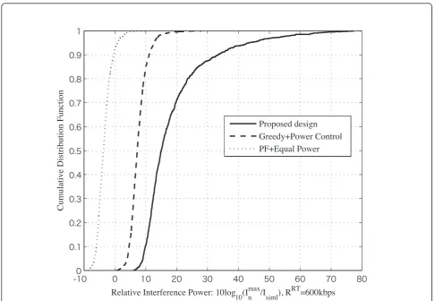
Figures 3 and 4 are CDF of achieved SINR and relative interference power of PU 1, which is located at the cell edge of the PS, respectively. The relative interference power is defined as 10log10(Imaxn /Isiml)(dB), where, Isiml is the simulated interference power. From Figures 3 and 4, we can see that the PF scheme cannot provide the PUs with predefined SINR because of the high interfer-ence. Compared to Greedy scheme and PF scheme, the proposed method not only achieves the highest SINR, which is much higher than predefined value, but also controls the SU-to-PU interference well.
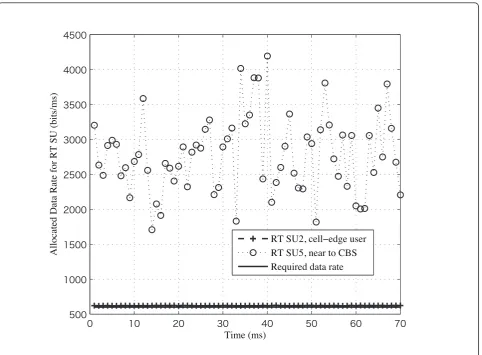
In Figures 5 and 6, the simulation results of QoS sup-port for RT and NRT SUs are shown respectively. In Figure 5, we setd2 = 500 m,d5 = 100 m, where,d2and
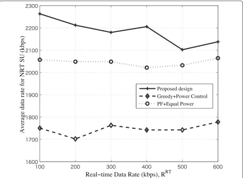
d5 are the distances from SU 2 and SU 5 to the CBS, respectively. We can see from this figure that SU 2, which is the cell edge user with great channel fading, can only obtain the basic QoS-guaranteed data rate 600 kbps; however, SU 5, which is near to the CBS with good channel state, can achieve much higher rate so as to maximize the system throughput. Figure 6 shows the average data rate of NRT SUs versus different RT data rate. Compared to conventinal schemes, the proposed design can achieve much higher average data rate. Table 1 Simulation parameters
Parameters Value
Number of PUsN 8
Number of SUsM 10
System bandwidthBw 2 MHz System center frequencyfc 1.9 GHz Total power at the PBS 10 W Total power at the CBSP0 13 W Predefined SINR of PUs in dB γpdB 10 dB Interference violation probabilitys(p) 0.01
Antenna gainGs 8 dBi
Number of subcarriersM 128
Path loss exponenta 4
Number of RT SUsI 5
Number of NRT SUsJ 5
Delay of RT servicedRT
i (time slots) 90
Symbol periodTs 40μs
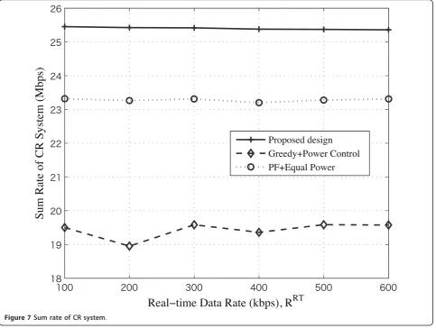
Figure 7 shows the sum rate of the CR system. Com-pared to the other two RA schemes, it yields a signifi-cant higher sum rate. For different RT data rate, the sum rate of CR system is almost the same due to the same available CBS power and spectrum resource. For the Greedy scheme, even though it can control the SU-to-PU interference, the spectrum efficiency is really low. From Figure 7, we can see the proposed design has the best performance.
5.2 Performance comparison between spectrum underlay and overlay
In practical systems, two systems may be overlapped with each other, and the primary bandwidth may not be used out, that is, the probability of non-active PU bands satisfiesPnon-active≥0.
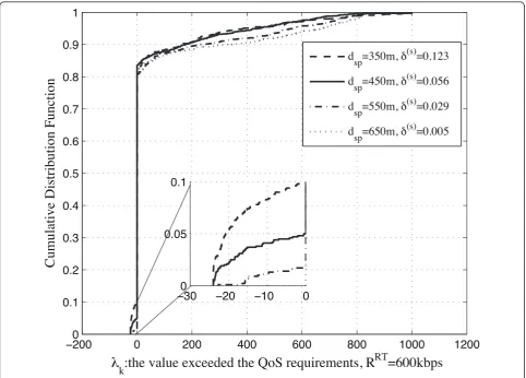
When CBS and PBS are too close to each other and the primary bands are all in use, it is difficult to control the MI with power control, or to provide satisfactory QoS to all SUs. Figure 8 is the CDF oflk at different CBS-PBS distance dsp, which has been changed from 350 to 650 m. Here, the simulation parameters are the
same with Section 5.1 andPnon-active= 0. We definePr {lk < 0} =δ(s), which is the secondary QoS-unsatisfac-tory probability. When δ(s)> 0.01, we consider that the CR system cannot guarantee the QoS for all SUs. From Figure 8, we can see that in order to limit the interfer-ence at the PUs and provide the QoS for ten SUs as well,dspcannot be very small. Whendsp= 650 m,δ(s)is only 0.005; whiledspdecreased to 550 m, δ(s)increased to 0.029. Then, we consider that the CR system when
dsp = 550 m cannot satisfy the requirements for all SUs at the same time. In this situation, we should choose other better sharing methods for the CR system.
Therefore, in order to improve the effectiveness of the coexistent system, we compared the performance between spectrum underlay and spectrum overlay shar-ing methods.
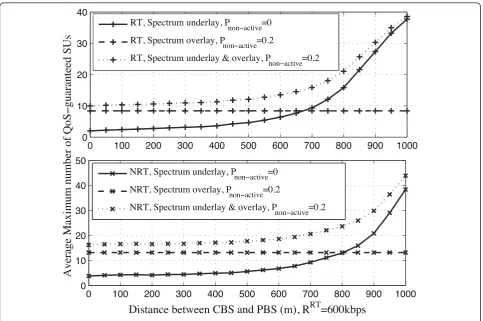
control the interference level to the active subbands). We set the probability of non-active PU bands to be
Pnon-active = 0 or 20%. When Pnon-active = 0, only the spectrum underlay sharing can be utilized for the CR system; while, whenPnon-active = 20%, both the spectrum underlay and spectrum overlay are available for the CR system to share the spectrum with PS.
From Figures 9 and 10, we can see that the maximum RT/NRT SU number and the sum rate of the CR system are increasing with the distance between the CBS and the PBS when utilizing the spectrum underlay scheme for bothPnon-active = 0 and 20%. However, the perfor-mance of the spectrum overlay sharing scheme is almost the same, and only related toPnon-active= 0, which is the available spectrum resource. Compared the performance of these sharing schemes in Figures 9 and 10, the spec-trum underlay has substantial higher specspec-trum efficiency and can be utilized for both Pnon-active = 0 and 20%. When Pnon-active = 0, the spectrum underlay & overlay sharing method is the best candidate for CR systems to access unlicensed spectrum.
6 Conclusions
A combined cross-layer RA and interference avoidance optimization design for downlink OFDMA-based MCR systems has been proposed. We utilize a predefined SINR and an interference violation probability at the primary receivers for the power allocation and interfer-ence control. QoS constraints transformation and IWF method have been analyzed to maximize the system throughput for the CR system and provide satisfactory QoS support for different services of the SUs. To obtain optimal solution, we developed a convex OP to solve the system utility function.
Compared to the conventional RA schemes, the pro-posed cross-layer design with the spectrum underlay shar-ing method could share the spectrum with the PUs more effectively. Simulation results illustrate that our proposed design has a significant performance gain. On the other hand, the comparision between the spectrum underlay and overlay has shown that if there is available subbands in the PS, it has the best spectrum efficiency with both the spectrum underlay and overlay sharing methods.
Acknowledgements
A part of this research has been supported by the Japa-nese Ministry of Internal Affairs and Communications under Strategic Information and Communications R&D Promotion Programme (SCOPE).
Appendix
1 Proof of proposition
In (7), the CDF of gspn,m,t is given by F(x) =Pr{X≤x}= 1−e(−x2/2σ2)
, x Î [0, ∞), s > 0. Then, for Equation (7), there is the following derivation:
Pr{Pk,m,tgspn,m,t·μ(d sp
n,t/d0)−α>Ilimm}=Pr
gspn,m,t> Ilim
m Pk,m,tμ(dspn,t/d0)−α
= 1−Pr
gspn,m,t≤ Ilim
m Pk,m,tμ(dspn,t/d0)−α
= 1−F
Ilim m Pk,m,tμ(dspn,t/d0)−α
≤δ(p)
(35)
Then, from (35), we has the following inequality:
F
Ilimm Pk,m,tμ(dspn,t/d0)−α
≥1−δ(p) (36)
Due to the monotone non-decreasing property of CDFs, from (36), the following power constraint on sub-carriermcan be obtained:
Ilimm Pk,m,tμ(dspn,t/d0)−α
≥F−1(1−δ(p)) (37)
From (37), the power limits for secondary subcarriers can be derived based on the primary performance tar-gets and the channel characteristics.
Pk.m,t≤
Ilim
m
μ(dspn,t/d0)−αF−1(1−δ(p)
(38)
where,Pk,m,tcan be written asPm,tinstead.
2 Proof of proposition
OP-A:
The functions (39) in OP-A are convex functions in convex set C={Lk,m,t={0, 1},Rk,m,t∈[0,Rmax]}. The largrangian function [19] of the above convex
optimization OP-A is: multiplier should be no less than zero.
Let {R∗k,m,t,L∗k,m,t,a∗m,t,b∗k,m,t,c∗k,m,t,e∗k,m,t,fk∗,m,t,h∗k} be an optimal solution. Then the Karush-Kuhn-Tucker (KKT) conditions are as following:
a∗m,t≥0,b∗k,m,t≥0,c∗k,m,t≥0,e∗k,m,t≥0,fk∗,m,t≥0,h∗k≥0(44)
b∗k,m,t(L∗k,m,t−1) = 0 (46)
c∗k,m,tL∗k,m,t= 0 (47)
e∗k,m,t(Rk∗,m,t−Rmax) = 0 (48)
fk∗,m,tR∗k,m,t= 0 (49)
h∗k
rReqk,τ −
τ
t=1
M
m=1
R∗k,m,tL∗k,m,t
= 0 (50)
L∗k,m,tln(2)2
R∗k,m,t
f
βk,m,tf
+e∗k,m,t−fk∗,m,t−h∗kL∗k,m,t= 0 (51)
⎛ ⎜ ⎜ ⎝2
R∗k,m,t
f −1
⎞ ⎟ ⎟ ⎠
βk,m,t
+a∗m,t+b∗k,m,t−ck∗,m,t+hk∗R∗k,m,t= 0
(52)
Equations (51) and (52) are obtained by setting ∂L/
∂Rk,m,t= 0 and∂L/∂Lk,m,t= 0, respectively. From (51), when L∗k,m,t= 0, we have
R∗k,m,t=flog2
(h∗kL∗k,m,t+fk∗,m,t−e∗k,m,t)βk,m,tf
ln(2)L∗k,m,t
(53)
According to (48) and (49), e∗k,m,t and fk∗,m,t cannot be positive at the same time. Therefore, when
R∗k,m,t = 0, e∗k,m,t= 0,fk∗,m,t≥0, then, according to (53),
h∗k≤ ln(2)
βk,m,tf
then, according to (53),
h∗k ≥2 Rmax
f ln(2)
βk,m,tf
; when
0<R∗k,m,t<Rmax,ek∗,m,t= 0,fk∗,m,t = 0, then, according to
(53), ln(2) βk,m,tf <
h∗k< 2 Rmax
f ln(2)
βk,m,tf
. To summarize, the
optimal rate allocation R∗k,m,t at time slottcan be:
R∗k,m,t=
⎧ ⎪ ⎪ ⎪ ⎪ ⎪ ⎪ ⎪ ⎪ ⎪ ⎪ ⎪ ⎨ ⎪ ⎪ ⎪ ⎪ ⎪ ⎪ ⎪ ⎪ ⎪ ⎪ ⎪ ⎩
0, h∗k≤ ln(2) βk,m,tf
flog2
h∗kβk,m,tf
ln(2)
, ln(2)
βk,m,tf <
h∗k<2
Rmax
f ln(2)
βk,m,tf
Rmax, h∗k≥2
Rmax
f ln(2)
βk,m,tf
(54)
Suppose that subcarriermhas been allocated to more than one SU, that is, there exists 0<L∗k,m,t <1 for SUs
k1, k2,...,kB,B> 1. From (46) and (47), we have b∗k,m,t= 0
and c∗k,m,t= 0. Then, from (52), we have
⎛ ⎜ ⎜ ⎝2
R∗k,m,t
f−1 ⎞ ⎟ ⎟ ⎠
βk,m,t
+h∗kR∗k,m,t =−a∗m,t
(55)
We define hk,m,t =
⎛ ⎜ ⎜ ⎝2
R∗k,m,t
f −1
⎞ ⎟ ⎟
⎠/βk,m,t+h∗kR∗k,m,t,
therefore, we have hk,m,t=−a∗m,t for allk=k1,k2,...,kB, that is hk1,m,t =hk2,m,t=· · ·=hkB,m,t.
However, for the left side in (55), unlessbk,m,tis equal for SUs k1,k2,..., kB, it is highly impossible that any of the twohk,m,tvalues will be equal. Sincebk,m,tare chan-nel state information, modeled as independent and ran-dom variables. Therefore, we conclude that for any time slot tand subcarrierm, there is only one SUk*, that is
method how to find this SU, which is similar to that analyzed in Appendix 3, will be omitted here.
Now, the proof of Proposition 2 will continue. We consider L∗k,m,t= 1 for SUk. The allocated rates for SU
kduringτtime slotsrkcan be calculated as following by using (54):
We define some probabilities:
Pr{a given subcarrier is allocated to SU k} =pk;
Pr
⎧ ⎨
⎩the power gain of the allocated subcarrier satisfies ln(2)
⎩the power gain of the allocated subcarrier satisfiesh∗k≥
2
Equation (56) can be calculated as:
rk=
where, m(t) is the available subcarrier number at time slott.
Similarly, at time slott, the optimal number of bit rate allocated to SUkis obtained:
M
Suppose that the allocation can achieve the QoS requirements for SUk, therefore, the allocated bit rates during τ time slots satisfied rk=rReqk,t τ, where, rkReq,t is
the required bit rate at each time slot. So, Equation (59) can be rewritten as:
M
SU kat time slot t. Then, it is difficult to satisfy the required bit raterkReq,t at each time slot, and the required bit rate duringτtime slots also cannot be satisfied, since
rk<rReqk,t τ due to limited primary bandwidth. To
guaran-tee the QoS requirments,M needs to be large enough. AssumeM®∞, so that at each time slot, there arem(t)≥
mreqthat can achieve SUs’requirements, where,mreqis the minimum number of required subcarrier. Therefore, for OP-A, to achieve the QoS and minimize the transmit power,m(t) should be equal tomreqat each time slot. IfM ®∞,τ
t=1m(t) =τmreq, and we can have:
M
m=1
R∗k,m,tL∗k,m,t=rkReq,t (61)
3 Proof of solution S*
In Problem OP-3, if we replace Rk,mby Rk,m=Rk,mf,
which can be obtained from (10). The following duality OP is obtained:
OP-B:
min
K
k=1
−λk (62)
s.t.
Pk,m−Pmaxm ≤0, K
k=1
M
m=1
Pk,m−P0≤0 (63)
K
k=1
Lk,m−1≤0, Lk,m−1≤0, −Lk,m≤0 (64)
Rk,mf −Rmax≤0, −Rk,mf ≤0 (65)
rReqk +λk− M
m=1
Rk,mf Lk,m= 0, −λk≤0 (66)
where, Pk,m= 2
Rk,m−1 βk,m .
The Lagrangian function [19,20] associated with the above duality problem OP-B can be written as:
LRk,m,Lk,m,λk,ξk,m,ϕ,ψm,φk,m,νk,m,ζk,m,εk,m,ηk,ςk an optimal solution set, then the KKT conditions state that [19]:
Equations (76)-(78) are obtained by setting
∂L/∂Rk,m= 0, ∂L/∂Lk,m= 0, and ∂L/∂lk = 0 respectively.
In order to analyze the KKT consitions and get the optimal solution, we have the following steps to solve Problem OP-B:
(1)Step 1:Power allocation
From (76), the following equation can be obtained:
2R∗k,m ln(2)
k,m cannot be both positive and they are all
nonnega-tive. So the optimal values of ζk∗,m and ε∗k,m can only be
one of the following cases:
ε∗
, that means we must have
ε∗k,m>0, ζk∗,m= 0. So, according to (73), we must have
Therefore, to summarize, the optimal value of R∗k,m is:
The following optimal power allocation P∗k,m= 2R∗max−1
pliers. Moreover,ωkis viewed as the IWF level for the SUkand will be discussed later.
(2)Step 2: Subcarrier allocation
For simplicity and in order to maximize the system throughput, L∗k,m is set to be either 0 or 1, and one sub-carrier must be allocated to any user. So, for any given time slot tand subcarrier m, there is only one SU k*
with a nonzero value of L∗k∗,m and L∗k∗,m= 1 according
Compare (82) with (83), we have
η∗
k∗R∗k∗,m≥η∗kR∗k,m (84)
The subcarrier allocation strategy for any subcarrierm
is same for several users, we will choose one SU arbitrarily.
(3)Step 3:IWF level
For all SUs, according to KKT conditions, when
λ∗
base water-level for all SUs.
From (68)-(70), if the optimal value* > 0, that means all the power has been used to optimize the system throughput. Therefore, the initial value of * and ξk∗,m
should be set to* > 0 and ξk∗,m>0to obtain the
maxi-mum system throughput. Therefore, to summarize, the water-filling levelωkis:
ωk=
The authors declare that they have no competing interests.
Received: 29 April 2011 Accepted: 9 February 2012 Published: 9 February 2012
References
1. Federal Communications Commission, FCC Spectrum policy task force report, Report of the Spectrum Efficiency Working Group. ET Docket no. 02–135 (Nov 2002)
2. J Mitola III, Cognitive radio: An integrated agent architecture for software defined radio, Ph.D. dissertation (Royal Institute of Technology (KTH), Stockholm, Swedem, 2000)
3. S Haykin, Cognitive radios: brain-empowered wireless communications. IEEE J Sel Areas Commun.23(2), 13–18 (2005)
4. TA Weiss, FK Jondral, Spectrum pooling: an innovative strategy for the enhancement of spectrum efficiency. IEEE Commun Mag.42(3), S8–14 (2004) 5. T Qin, C Leung, Fair adaptive resource allocation for multiuser OFDM
cognitive radio systems, inProc 2nd Int Conf CHINACOM, Shanghai, China, 115–119 (Aug 2007)
6. A Attar, O Holland, MR Nakhai, AH Aghvami, Interference limited resource allocation for cognitive radio in orthogonal frequency-division multiplexing networks. IET Commun.2(6), 806–814 (2008). doi:10.1049/iet-com:20070355 7. H Su, X Zhang, Cross-layer-based opportunistic MAC protocols for QoS
provisionings over cognitive radio wireless networks. IEEE J Sel Areas Commun.26(1), 118–129 (2008)
8. JW Mwangoka, KB Letaief, Z Cao, Robust end-to-end QoS maintenance in non-contiguous OFDM based cognitive radios, inProc IEEE ICC, Beijing, China, 2905–2909 (May 2008)
9. R Wang, VKN Lau, L Lv, B Chen, Joint cross-layer scheduling and spectrum sensing for OFDMA cognitive radio systems. IEEE Trans Wirel Commun.8(5), 2410–2416 (2009)
10. Y Zhang, C Leung, Cross-layer resource allocation for mixed services in multiuser OFDM-based cognitive radio systems. IEEE Trans Veh Technol.
58(8), 4605–4619 (2009)
11. TA Weiss, J Hillenbrand, A Krohn, FK Jondral, Mutual interference in OFDM-based spectrum pooling systems, Proc of IEEE 59th Vehicular Technology Conference (VTC 2004-Spring), Milan, Italy, 1873–18774, (2004) 12. W Ren, Q Zhao, A Swami, Power control in cognitive radio networks: how
to cross a multi-lane highway. IEEE J Sel Areas Commun.27(7), 1283–1296 (2009)
13. G Zhao, GY Li, C Yang, Proactive detection of spectrum opportunities in primary systems with power control. IEEE Trans Wirel Commun.8(9), 4815–4823 (2009)
14. A Goldsmith,Wireless Communications, (Cambridge University Press, Cambridge, 2005)
15. H Celebi, H Arslan, Cognitive positioning systems. IEEE Trans Wirel Commun.6(12), 4475–4483 (2007)
17. M Ben Ghorbel, H Nam, MS Alouini, Discrete rate resource allocation for OFDMA cognitive radio systems with location information, inPIMRC workshops 2010, Instanbul, Turkey, 247–251 (Sep 2010)
18. Y Zhang, Resource allocation for OFDM-based cognitive radio systems, Ph. D. dissertation (Univ. British Columbia, Vancouver, BC, Canada, 2008) 19. S Boyd, L Vandenberghe,Convex Optimization, (Cambridge University Press,
Cambridge, 2004)
20. DG Luenberger,Optimization by Vector Space Methods, Wiley, NewYork, (1969)
21. K Kim, Y Han, S-L Kim, Joint subcarrier and power allocation in uplink OFDMA systems. IEEE Commun Lett.9, 526–528 (2005). doi:10.1109/ LCOMM.2005.1437359
22. Y Ma, Rate maximization for downlink OFDMA with proportional fairness. IEEE Trans Veh Technol.57, 3267–3274 (2008)
doi:10.1186/1687-1499-2012-41
Cite this article as:Peng and Fujii:Joint cross-layer resource allocation and interference avoidance with QoS support for cognitive radio systems.EURASIP Journal on Wireless Communications and Networking2012 2012:41.
Submit your manuscript to a
journal and benefi t from:
7Convenient online submission
7Rigorous peer review
7Immediate publication on acceptance
7Open access: articles freely available online
7High visibility within the fi eld
7Retaining the copyright to your article