R E S E A R C H
Open Access
Contactless power and data transmission for
underwater sensor nodes
Yin-guo Huang
*, Cheng Fang and Xing-fei Li
Abstract
When the technology of wireless sensor network is applied to ocean monitoring, the ocean underwater
monitoring system will become a distributed network system. That could improve the level of ocean monitoring significantly. But most of the current ocean monitoring equipments work independently, and it is difficult to form them into a sensor network. To set up a sensor network, electric energy supply and data transmission are the chief problem, especially for the underwater sensor nodes. To solve this problem, a new method for
contactless power and data transmission is proposed. It operates with the principle of electromagnetic coupling. Power and data are transmitted through a mutual channel. This channel is realized by the structure of a
two-stage electromagnetic coupler. Here, steel rope is used as the closed steel ring to compose an electromagnetic coupler. Since steel rope is widely used in the current underwater equipments, the
transmission channel of power and data can be realized without changing the existing structure. Furthermore, because of contactless transmission the sensor network has good expansibility and convenient configuration of its nodes for underwater applications. A voltage transformation model for the two-stage electromagnetic coupler is constructed and the transmitting principle of power and data is analyzed based on the model. According to the energy transmission efficiency and the bit error rate, an experimental prototype is designed and fabricated. Finally, the prototype testing of power transmission, data transmission, and reactive power compensation are carried out. The experimental results show that the proposed method for contactless power and data transmission is feasible and it is suitable for the application of underwater sensor nodes.
Keywords:Power and data transmission, Electromagnetic coupling, Sensor nodes, Reactive power
compensation
1. Introduction
The ocean underwater monitoring system is a main part of ocean stereo monitoring network. It can obtain the data of ocean dynamics parameters and environmental elements, and it works in real-time, continuously and rapidly. That data include salinity, temperature, dissolved oxygen, chlorophyll, heavy metal, ocean current, and so on. The ocean underwater monitoring is characterized by the vast area and too many parameters. The monitoring system should meet the requirements of stereo monitoring with the characteristics of multipoint, multiple-profile, and network [1]. Therefore, it is important to introduce the technology of wireless sensor network (WSN) into the ocean monitoring system. With WSN, a distributed
network system for ocean monitoring can be constructed. That will greatly improve the monitoring level [2].
The current monitoring systems usually operate in the mode of single-point or scanning, such as buoy, sub-mersible buoy, underwater robot, shipborne equipments, and so on. When in scanning mode, the single-point equipment can realize a kind of point and multi-profile monitoring by navigation. Although most of these equipments have the function of communication, they work as independent system and it is difficult to form them into a sensor network. As a sensor node, the underwater equipment has to realize the demand of long-term, networking and autonomous work. Therefore, power feeding and data transmission are the chief problem for this application. In this area, some related research works have been conducted. Because most of the current underwater equipments use batteries as the power, the * Correspondence:[email protected]
State Key Laboratory of Precision Measuring Technology and Instruments, Tianjin University, Tianjin 300072, China
technology of low-power design gets much attention, such as the low-power underwater seismograph designed by Manuel et al. [3]. Tomisa et al. [4] utilized solar energy to power the ocean buoy with low maintenance cost. Ahnet al. [5] researched a new kind of buoy, in which wave energy was converted into electric power. Some other research on energy conversion for ocean
applications was also achieved, such as tidal energy [6] and ocean thermal energy conversion [7]. In underwater data transmission area, acoustic communication is the uppermost method at present [8]. Jane et al. [9] employed communication cables to transfer data between buoy and sensors.
This article proposes a new method for power feed-ing and data transmission based on electromagnetic coupling. It implements power and data transmission with a closed steel ring, which is widely used in the existing underwater equipments. Here, the closed steel ring serves as a transmission channel, and also a supporting structure to fasten the underwater sen-sors. Based on the proposed method, an experimental prototype is designed, which realizes contactless power and data transmission in the same channel for the underwater sensors.
2. System structure
2.1. The structure of underwater sensor network
As shown in Figure 1, the presented method is suitable for the underwater sensor network with a hierarchical topology structure, whose elementary unit is a cluster. This network is constructed on the basis of the com-mon using structure of buoy. The cluster comprises a monitoring platform and a sensing unit. The overwater monitoring platform which communicates with other nodes using GPRS plays the role of backbone node. The underwater sensing unit includes many sensors, the so-called general nodes, which are configured along the direction of the closed steel ring. They can get the profile information at different depth. There-fore, an underwater distributed network can be built up by organizing network between clusters scatted in a specific ocean area.
2.2. The cluster based on contactless power and data transmission
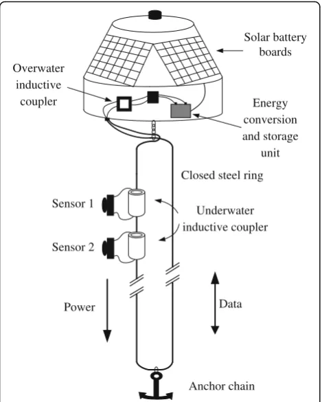
Figure 2 gives the cluster structure with the function of contactless power and data transmission. It is constructed based on a typical architecture of buoy.
GPRS
Figure 1The structure of underwater sensor network.
Data
Figure 2The cluster structure based on contactless power and data transmission.
Transformer A Transformer B
Coil 1 Coil 2
Coil 3
First, the overwater monitoring platform converts solar energy into electric power and stores it to power the whole cluster node. Power and data are transferred on the mutual channel between the monitoring platform and the underwater sensor. That channel is made up of overwater inductive coupler, closed steel ring, and underwater inductive coupler. Every sensor node fixed on the closed steel ring has an underwater inductive coupler, through which the sensor node obtains power supply and sends the measured data to the monitoring platform.
Because of electromagnetic coupling, there is no tight electrical contact between the closed steel ring and the sensor nodes. The sensor nodes can be fixed at arbitrary depth along the closed steel ring. It is easy to mount the sensor nodes. For instance, temperature sensor, salinity sensor, and ocean current sensor are arranged at different depth. That contributes to the good expansibility of the sensor network.
3. The method for contactless power and data transmission
3.1. Transmission principle based on electromagnetic coupling
The method for contactless power and data transmission is shown in Figure 3. Based on the principle of electro-magnetic coupling, a structure of double-transformer is designed. The closed steel ring is not only the secondary coil of transformer A, but also the primary coil of transformer B.
According to the electromagnetic induction law, the input voltageuiof transformer A is given by
ui¼N1dϕ11 dt ¼L1
di1
dt ð1Þ
where N1 is the number of turns of coil 1, L1 is the
self-inductance of coil 1, ϕ11 is the main flux of the
coupler, and i1 is the current flowing through coil 1.
Carrier 0
Carrier 1
Original signal
Modulating
signal
Figure 4FSK modulation.
Driver
Master MCU
Overwater inductive
coupler
Overwater machine Power Underwater machine
Closed steel ring Inverter
Data
undererwater inductive
coupler
FSK Receiver 1:1 Amplifier
Sensor
Slaver MCU FSK Transmitter
Super capacitor Rectifier
Two coils could not be fully coupled actually, and the coupling coefficientk1is
k1¼ ffiffiffiffiffiffiffiffiffiffiM L1L2
p ð2Þ
where M is the mutual inductance of the two coils and L2 is the self-inductance of coil 2. The relationship
between the changes of magnetic flux in the two-layer coils is as follows:
dϕ12 dt ¼k1
dϕ11
dt ð3Þ
where ϕ12 is the flux of coil 2. According to the above
equation, the voltageu2of coil 2 can be obtained
u2¼N2dϕ12
(single turn). Similarly, the voltage relationship of transformer B can be calculated. Finally, the output voltageu3is
the coupling coefficient of transformer B.
3.2. Implementation of power and data transmission Equation (5) gives the voltage transformation model of the two-stage coupler. That is the model for delivering electric energy. Both of the monitoring platform and underwater sensor should be powered with DC, while electromagnetic coupler needs AC. So, the energy delivery is a conversion process of DC/AC–AC/DC.
In Equation (5), ui can be denoted as ui(t) = f(t) cos
(ωt), where f(t) is the data to be sent. Accordingly, u3
would include the information of f(t). Here, the data signal is modulated by the carrier cos (ωt) to fit the transmission channel. Consequently, the transmission distance can be tens of meters or even hundreds of meters by signal modulation.
In order to improve the anti-noise and anti-decay of underwater data transmission, the technology of frequency shift keying (FSK) is used. The signal to be delivered is modulated by carrier frequency. The working process is shown in Figure 4. The frequency of carrier 0 is lower than that of carrier 1. After modulating, signals 0 and 1 in the original binary signal are, respectively, corresponded to carriers 0 and 1. Finally, the modulating signal is received by the monitoring platform and then it is demodulated to revert to the original signal.
4. Prototype design and experiments 4.1. Prototype design
An experimental prototype is designed and Figure 5 gives its block diagram. It includes an overwater machine (monitoring platform) and an underwater machine (underwater sensor node). Both are controlled by MicroControllerUnit (MCU). The overwater machine has two kinds of work mode, power-sending and data-receiving. When in power-sending mode, the master-MCU generates sinusoidal pulse width modulation wave and sends it to the driver. Then the inverter generates sine wave under the control of the driver. Accordingly, the underwater machine works in power-receiving mode. That mode comprises two steps, rectification of the sine wave and charging the super capacitor. When the underwater machine works in data-sending mode, slave-MCU writes data to FSK transmitter. FSK trans-mitter outputs sine wave whose frequency is modulated. At the same time, the overwater machine receives the sine signal through a kind of 1:1 amplifier. Then the data demodulated by the FSK receiver are read out by the master-MCU.
In terms of Equation (5), the coupling coefficient has a great influence on the transmission efficiency. It is the key parameter to design the prototype. The Figure 6The picture of the prototype.
Table 1 The results of power and data transmission experiments
Parameters Transmission distance
2 m 10 m
Transmission efficiency 0.78 0.33
material and structure of the coupler determine the coupling coefficient.
The higher permeability of the coupler is conducive to the reduction of the magnetic leakage and the im-provement of the coupling efficiency. The transmis-sion efficiency is also related to the loss of the coupler. Different materials have different loss value per unit volume. Therefore, the electromagnetic coup-ler material should have such properties: (1) soft mag-netic material, (2) small loss in highfrequency, (3) great initial permeability, and (4) great saturation magnetic induction. According to the above requirements, Fe-based nano-crystal material is selected to design the coupler.
For the convenience of fabricating, the shape of the coupler core is designed as rectangle. The area product method is used to design its size. With that method, there are several factors to be considered, among which the power is the most important factor. The area product method is given by
Ap ¼ Pt
where Ptis the total apparent power,Bm is the magnetic
flux density,f is the operating frequency of the trans-former, Kf is the waveform factor (4.0 for square
wave, 4.44 for sine wave), Kuis the window utilization
coefficient, and J is the current density. For the same
apparent power, increasing the window utilization factorKu, the working frequencyf, the magnetic density
Bm, and current density J can reduce the window area
product, and then reduce the volume of the electro-magnetic coupler. Similarly, for the same area product, increasing the above parameter values could improve the total apparent power of the electromagnetic coupler. The fabricated prototype is shown in Figure 6.
4.2. Experiments on the prototype
Changing transmission distance, power, and data trans-mission experiments are carried out. (1) The transtrans-mission distance is 2 m. First, a high-power resistor is used as the load of the underwater machine. The overwater machine transmits electric energy to the underwater machine and the transmission efficiency is calculated. Then, under the same working conditions the underwater machine sends data while the overwater machine receives them. The bit error rate is calculated. (2) The transmission distance is 10 m. Repeat the above experiments. Table 1 gives the experimental results.
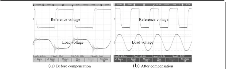
Increasing the transmission distance, the bit error rate is the same while transmission efficiency decreases. Because other working conditions keep unchanged, it can be deduced that the decline of transmission efficiency is directly related to the transmission distance. Thereby, reactive power compensation experiment is carried out to improve the transmission efficiency. The transmission model of electric energy is shown in Figure 7. Between the overwater machine and the underwater machine, the impedance of the closed steel ring is replaced by resistors and inductors in series.
Due to the existence of the inductance, the prototype inevitably generates reactive power. In a pure inductance AC circuit shown in Figure 8, there is a lead phase 90° between the phase of the voltage UL and that of
the current I. Accordingly, there are a phase lag of 90° in the pure capacitance circuit and zero phase difference in the pure resistor circuit. According to the principle of the impedance transformation, a resonant capacitor is connected in parallel to the secondary coil of the underwater coupler. That is equivalent to the connection of a capacitor to the primary coil. By adjusting the capacitance value, the phase difference Overwater
machine Resonantcapacitor Underwatermachine
R L
Figure 7The transmission model of the prototype.
I
Δϕ between the synthesized voltage U and current I can be reduced. When Δϕ = 0, the resonance would occur. In the resonance state, the working frequency can be given by
f ¼ 1
2πpffiffiffiffiffiffiffiLC ð7Þ
In the ideal condition, the power factor of the resonance circuit is 1 and the reactive power is zero.
When the transmission distance is 10 m, the actual equivalent resistance and inductance of the closed steel ring are 0.5Ω and 200 μH, respectively. According to Equation (7), the theoretical value of the compensating capacitor is 1.15μF and here it takes a value of 1.0μF. The transmission experiments on the compensated prototype are conducted once again with the transmis-sion distance of 10 m. Figure 9 shows the load voltage waveforms before and after compensation. The experi-mental results indicate that the transmission efficiency increases to 0.56 and the bit error rate still keeps a value of 0%.
4.3. Discussion
The above experiments prove that the method for power and data transmission based on electromagnetic coupling is feasible. For data transmission, the bit error rate is 0% when the transmission distance is ei-ther 2 or 10 m. That is due to good anti-interference ability of FSK modulation. If the transmission distance further increases, the bit error rate should still keep to a low level. For power transmission, the transmission efficiency declines with the increase of the transmis-sion distance. Reactive power compensation plays an important role in improving the transmission effi-ciency. In addition, some other factors influence the
transmission efficiency, such as the area of the closed steel ring, wattful loss, inverter efficiency, and the ac-curacy of the compensation model parameters. Those factors need further study. Therefore, it is feasible to further improve the transmission efficiency based on the present prototype.
5. Conclusion
The underwater sensor nodes should meet the require-ments of long-term, networking and autonomous work-ing. Therefore, the key to constructing a distributed sensor network is to solve the problem of power and data transmission. The principle of electromagnetic coupling is innovatively applied to contactless power and data transmission for underwater sensor nodes. With a two-stage electromagnetic coupler and closed steel ring structure, power and data are transmitted on the same channel. The voltage transformation model is established and the transmission process is analyzed. An experimental prototype is designed and fabricated. The results of test experiments prove that the presented method is feasible. This research provides a new method of power and data transmission for underwater sensor nodes. That method can directly be used in the existing underwater monitoring equipments, which will improve the ocean monitoring performance of real-time, maintenance-free, and expansibility.
Competing interests
The authors declare that they have no competing interests.
Acknowledgement
This study was supported by the National Natural Science Foundation of China (60972129) and the Science and Technology Support Project (State Key Laboratory of Mechatronical Engineering and Control).
Received: 6 January 2013 Accepted: 25 February 2013 Published: 20 March 2013
Reference voltage
Load voltage Load voltage
Reference voltage
(a)
Before compensation(b)
After compensationReferences
1. HM Murphy, GP Jenkins, Observational methods used in marine spatial monitoring of fishes and associated habitats. A review. Mar. Freshw. Res. 61(2), 236–252 (2010)
2. JJ Kong, JH Cui, DP Wu, M Gerla,Building underwater ad-hoc networks and sensor networks for large scale real-time aquatic applications, in Proceedings of IEEE Military Communications Conference (MILCOM 2005)(Atlantic City, USA, 2005), pp. 1535–1541
3. A Manuel, X Roset, J Del Rio, DM Toma, N Carreras, SS Panahi, A Garcia-Benadi, T Owen, J Cadena, Ocean bottom seismometer: design and test of a measurement system for marine seismology. Sensors12(3), 3693–3719 (2012) 4. T Tomisa, S Krajcar, D Pinezic,Multipurpose marine buoy, in The 50th International
Symposium ELMAR (ELMAR 2008)(Croatia, Zadar, 2008). pp. 401-405
5. KK Ahn, DQ Truong, HH Tien, J Yoon, An innovative design of wave energy converter. Renew. Energy42(2), 186–194 (2012)
6. YS Cho, JW Lee, W Jeong, The construction of a tidal power plant at Sihwa Lake, Korea. Energy Sources34(14), 1280–1287 (2012)
7. S Goto, Y Motoshima, T Sugi, Construction of simulation model for OTEC plant using Uehara cycle. Electric. Eng. Jpn.176(2), 1–13 (2011) 8. W Zhu, M Zhu, Y Wu, B Yang, L Xu, X Fu, F Pan, Signal processing in
underwater acoustic communication system for manned deep submersible "Jiaolong". J. Acoust. Soc. Am131(4), 3238 (2012)
9. T Jane, R Christopher, G Antonio, K Taimur, F Steve, H Ian, B Nathan, V Chris M Ian, Real world issues in deploying a wireless sensor network for oceanography, inWorkshop on Real-World Wireless Sensor Networks (RWWSN, Stockholm. Sweden2005, 307–322 (2005)
doi:10.1186/1687-1499-2013-81
Cite this article as:Huanget al.:Contactless power and data transmission for underwater sensor nodes.EURASIP Journal on Wireless Communications and Networking20132013:81.
Submit your manuscript to a
journal and benefi t from:
7Convenient online submission 7Rigorous peer review
7Immediate publication on acceptance 7Open access: articles freely available online 7High visibility within the fi eld
7Retaining the copyright to your article