The Framework of Image Recognition Based on
Modified Freeman Chain Code
Haswadi Hasan
[email protected]
Faculty of Computer Science and Information System (FSKSM) Universiti Teknologi Malaysia
Skudai, 81310, Malaysia
Habibollah Haron
[email protected]
Faculty of Computer Science and Information System (FSKSM) Universiti Teknologi Malaysia
Skudai, 81310, Malaysia
Siti Zaiton Mohd Hashim
[email protected]
Faculty of Computer Science and Information System (FSKSM) Universiti Teknologi Malaysia
Skudai, 81310, Malaysia
Abstract
Image recognition of line drawing involves feature extraction and feature comparison; works on the extraction required the representation of the image to be compared and analysed. Combining these two requirements, a framework that implements a new extraction algorithm of a chain code representation is presented. In addition, new corner detection is presented as pre-processing to the line drawing input in order to derive the chain code. This paper presents a new framework that consists of five steps namely pre-processing and image processing, new corner detection algorithm, chain code generator, feature extraction algorithm, and recognition process. Heuristic approach that is applied in the corner detection algorithm accepts thinned binary image as input and produces a modified thinned binary image containing J characters to represent corners in the image. Using the modified thinned binary image, a new chain code scheme that is based on Freeman chain code is proposed and an algorithm is developed to generate a single chain code series that is representing the line drawing input. The feature extraction algorithm is then extracts the three pre-defined features of the chain code for recognition purpose. The features are corner properties, distance between corners, and angle from a corner to the connected corner. The explanation of steps in the framework is supported with two line drawings. The results show that the framework successfully recognizes line drawing into five categories namely not similar line drawing, and four other categories that are similar but with attributes of rotation angle and scaling ratio.
Keywords:Corner Detection, Chain Code, Line Drawing, Feature Extraction, Recognition
1. INTRODUCTION
recognition are discussed, and then the proposed framework and steps taken are detailed in Section 3. Section 4 examines the experimental result of the framework that is supported with line drawing examples. Finally, conclusion and discussion is presented in Section 5.
2. FRAMEWORK IN IMAGE RECOGNITION
As mentioned earlier, steps in image recognition are including pre-processing, image processing, data representation and feature extraction. This section presents few previous works on image recognition and steps involved. In each step, new algorithm or representation is proposed and they are discussed in this section as motivation and comparison in the development of a new framework in image recognition.
The literature review is divided into three categories namely works about the framework on image recognition and its feature identification and extraction, input of the feature extraction especially the chain code representation, and the steps in image processing of the input image especially corner detection.
The previous works summarizes all works that accepts chain code as its input or data representation, and detecting corner based on chain code. The framework in [1-3] provides basis in identifying features of image recognition of this work. The works by [2-5] show the application of chain code in image recognition and feature extraction. The corner detection in [6] demonstrates the application of chain code in detecting corner while [7] points out how corner detection apply chain code scheme as curvature. Works by [8] proposes new chain code scheme in image retrieval.
Based on these three categories of previous works, it shows that the image recognition and feature extraction can possibly include corner detection as part of pre-processing and image processing step. The study also shows that chain code is relevant scheme and representation in image recognition and feature extraction. They give motivation and ideas on new framework in image recognition particularly for line drawing that combines feature extraction, corner detection and chain code representation.
3. THE PROPOSED FRAMEWORK
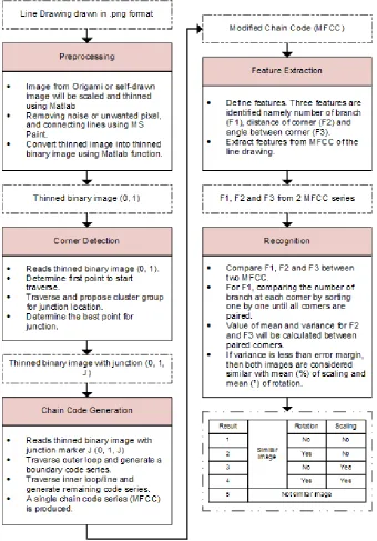
3.1 The Framework
FIGURE 1: The Proposed Line Drawing Recognition Framework.
3.2 Data Definition and Pre-Processing
3.3 Development of Corner Detection Algorithm
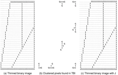
This step reads cleaned TBI and creates a modified TBI with J character in the image. The module involves two phases. First, starting point to traverse is determined. Second, cluster grouping is performed that is labelling the TBI with temporary label ‘G’, creating vector, generating vector list, and elimination of path and vector. The result of corner list in term of new TBI with J character is produced.
Any gate location is marked with G character and cluster member with + character. Any cluster in image will be grouped so that cluster exit gate which defines start and stop point for branch can be searched. Tracker movement is depends on the number of gates left untouched on current cluster before moving on to another cluster, while the current cluster is always referring to the latest cluster found.
To determine corner position in every cluster, vector creation is executed using cluster gate list that is either a beginning or end of a branch. Since connection between gates is not included in the list, path tracing between gates is inevitable. Combined with the need to include line angle namely inclination or degree of slope as its properties, edge detection is concurrently performed here since it involves scanning for slope changes. A box or window is maintained as reference slope and moved throughout the path trace while the actual branch slope will be calculated from the branch start until current point. When the fluctuation between the slopes has passed over the accepted limit, a corner is declared as found.
Line vectors are created based on cluster gates to find corners located in every cluster by line extrapolation. Every cluster member will be cross-marked its point distance from line vectors attached cluster and the location with lowest value (lowest distance) will be chosen as a corner in the cluster. Newly appointed corner is tested for its connectivity with all gates in corresponding cluster to ensure that corner is enough for the cluster or additional corner is required. Now, all corner locations have been found and will be marked with J character in the line drawing to form a modified TBI.
3.4 Definition of New Chain Code Scheme and Development of Its Generator
This framework section proposed a new modified Freeman chain code scheme (MFCC). The development of this chain code scheme is parallel with the development of the chain code generator. The scheme is based on Freeman chain code but with additional character started from A, B, C…Z not to represent the direction of the pixel but the corner label passed during tracing. The chain code scheme is defined to have classification for outer loop and inner loop of the line drawing: outer loop is derivation of codes in the series of the boundary while inner loop is for remaining inner lines. The MFCC is a single chain code series and the reverse traversal of the code will produce the same source line drawing.
Using TBI with label corner J (0, 1, J) as input, tracking point will be set at the most bottom left pixel of image as starting location. The tracing will start from here and repeatedly tests for current position and neighbouring pixels for next move direction. The unlabelled corner previously marked its location with J, will be assigned a label that follows the latest used label. For starting point, the corner will be assigned 'A' character as its label and the corner is recorded in the chain code. Every corner found during tracing process is recorded in a First In Last Out (FILO) stack for rollback ability when the tracing reaches the end of any path. The boundary of line drawing will be used first for path traversing until the tracking point reaches back the starting point.
3.5 Defining the Features and Development of the Extraction Algorithm
This step involves two stages namely defining features to be used in the recognition, and extracting the features of the line drawing based on the generated MFCC. Identifying features of the line drawing is based on the geometric and topological properties of a line drawing. The three features are number of branches at each corner (F1), distance between corners (F2), and angle between corners (F3). Before extracting the features, layer where the corner resides in the line drawing must be determined starting from the boundary layer (outer loop) and moving into the inner loop based on corner linkage.
For F1, two properties is extracted namely the number of branches and the interconnectivity between corners. A table is created to represent these features. For F2 and F3, the calculation of these features is performed by a heuristic approach producing two values namely distance (length) in pixel for each corner, and branch angle at each corner. In MFCC, a branch will be found between 2 corner markers with its distance and angle will be derived based on directional codes defining the branch. Pythagoras theorem will be used to calculate the distance (F2) while the angle (F3) is using tangent formulation. Value of F1, F2 and F3 will be stored in corner property list, where the list is unique for each compared MFCC.
3.6 Recognition Process
Recognition involves comparison between two line drawings and it is based on the values of F1, F2 and F3. All features must be considered matched or accepted so that the recognition session to be declared successful. For F1, comparison of properties for each corner between two line drawings is performed. The list of corner properties with the number of branches at each corner for tested line drawing is rotated by one displacement until the quantity in both lists is matched. Corner labels are also important to be matched, but the pairing is limited to be performed on outer loop corners only since the labelling is in sequential order for this segment.
After F1 analysis is satisfied, analysis for F2 and F3 is performed by calculating the means and variances of both distance and angle. For F2, mean value represents ratio (%) of the scaling process while mean for F3 represents the degree of rotation occurred between two line drawings. Variances for both F2 and F3 are used to measure on how far a set of distance and angle values are spread out among them against a preset limit. Thus for these features, variances are used as rejection/acceptance criterion in the recognition process.
4. EXPERIMENTAL RESULT
Result on two line drawings tested on the framework is presented in this section. The discussion on input and output of four steps in the framework of first line drawing (LD1) namely pre-processing, corner detection, generating the chain code and deriving features are presented. Next, second line drawing (LD2) and its features is presented as input of the fifth step, recognition process. The details of the first four steps for LD2 are not given because of its similarity in steps taken in LD1. After the features of LD1 and LD2 are obtained, the recognition process is conducted and conclusion of the recognition is displayed. The following sub-sections show the input and output of each step in the framework.
4.1 Pre-processing
(a) Line Drawing 1 (LD1) (b) The thinned image of LD1
FIGURE 2: The line drawing and its thinned image.
(a) Thinned binary image (b) Clustered pixels found in TBI (c) Thinned binary image with J
FIGURE 3: The TBI and its modification until final version with J character.
4.3 Chain Code Generation
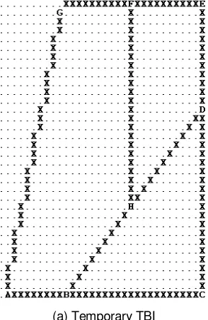
related to the derived MFCC shown in Fig. 4(b). Based on the algorithm, if Fig. 4(a) is traversed from A (most bottom left pixel) and continue the traversal, it will lead to the character B until H.
A000000000B000000000000000000000C 222222222222222222222D22222222222 2E44444444444F44444444445G6656665 6665665666566656656665666AGF66666 666666666666666666H11111111111DH5
555555555B
(a) Temporary TBI (b) The MFCC Chain Code
FIGURE 4: TheMFCC Chain Code Generation.
4.4 Feature Extraction
Fourth step in the framework reads the MFCC and produce a table consist of values of Feature 1 (F1), Feature 2 (F2) and Feature 3 (F3) as shown in Table 1. For F1, number in bracket in Current column indicates the number of branches from the corner, while Target column represents the connectivity of neighbouring corner from the corner. For F2 and F3, their values of distance and angle are shown in respective column. Distance represents the value of distance from Current corner to Target corner in unit pixel while Angle symbolizes angle value to point to Target corner from Current corner.
Feature 1 Feature 2 Feature 3 Feature 1 Feature 2 Feature 3 Corner Properties Distance
(unit pixel)
Angle (°)
Corner Properties Distance (unit pixel)
Angle (°)
Current Target Current Target
A (2) B 9.00 0.00 E (2) D 12.00 270.00
G 32.99 75.96 F 11.00 180.00
B (3)
A 9.0 180.00
F (3)
E 11.00 0.00
C 21.00 0.00 G 11.05 185.19
H 14.14 45.00 H 23.00 270.00
C (2) B 21.00 180.00 G (2) F 11.05 5.19
D 21.00 90.00 A 32.98 255.96
D (3)
C 21.00 270.00
H (3)
F 23.00 90.00
E 12.00 90.00 B 14.14 225.00
one of recognition result enumerated in Table 2. The result from recognition also provides angle of rotation and ratio of scaling of LD2 from LD1 based on mean values found during variance calculation in recognition algorithm.
Result
Similar image
Rotation Scaling
1 No No
2 Yes No
3 No Yes
4 Yes Yes
5 Not similar image
TABLE 2: Category of recognition result.
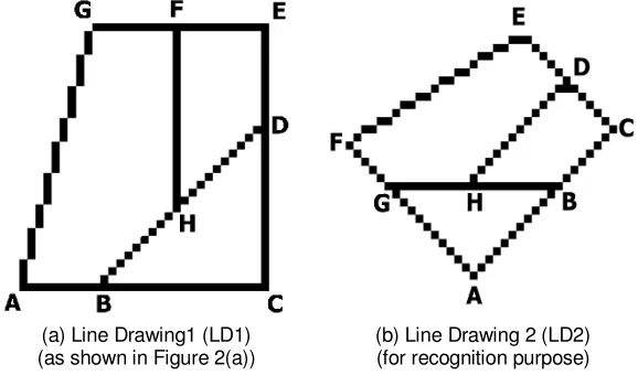
Fig. 5(a) and 5(b) show example of line drawing 1 (LD1) and 2 (LD2), respectively. The features of LD1 are as shown in Table 1 while features of LD2 are shown in Table 3. These tables will be used in recognition process.
(a) Line Drawing1 (LD1) (as shown in Figure 2(a))
(b) Line Drawing 2 (LD2) (for recognition purpose)
FIGURE 5: The input of recognition process with corners labelled.
Feature 1 Feature 2 Feature 3 Feature 1 Feature 2 Feature 3 Corner Properties Distance
(unit pixel)
Angle (°)
Corner Properties Distance (unit pixel)
Angle (°)
Current Target Current Target
A (2) B 15.56 45.00 E (2) D 8.60 324.46
G 15.56 135.00 F 24.70 211.76
B (3)
A 15.56 225.00
F (2) E 24.70 31.76
C 9.90 45.00 G 7.07 315.00
H 12.00 180.00
G (3)
F 7.07 135.00
C (2) B 9.90 225.00 A 15.56 315.00
D 8.49 135.00 H 10.00 0.00
D (3)
C 8.49 315.00
H (3)
G 10.00 180.00
E 8.60 144.46 B 12.00 0.00
H 18.38 225.00 D 18.38 45.00
TABLE 3: Value of features for LD2
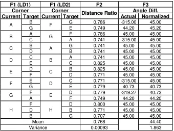
Distance Ratio represents the scaling factor of the new line drawing. For F3, the angle difference (Angle Diff.) is calculated based on the values of angle in Table 1 and 3. The values are then normalised. The normalised values indicate the rotation angle of the operation. Table 4 shows the value of mean and variance for F2 and F3. For F2, the value mean 0.768 indicates that the 76.8% scaling had happened for LD2. For F3, the value 44.40 indicates that line drawing 2 also have been rotated 440 with the rotation direction will be conferred from the actual angle difference value since the information is lost when angle normalization is executed. The exact answer would be the LD1 has been resized to 75% and 45°CW rotation to form LD2.
The value of variance is to measure structure lines properties uniformity. This value should be small enough to show that the line drawing 2 is really based on the line drawing 1. To judge how small the variance value must be is by comparing it to generic error margin set so that it must be lower than this value. If error margin is set to 0.1 for F2 and 15 for F3, the comparison can be allowed that LD2 is similar to LD1 after 76% scaled and 450 rotated clockwise. This acceptance is because variance value for F2 is 0.00093 and F3 is 1.863 that is less than error margin set.
F1 (LD1) F1 (LD2) F2 F3
Corner Corner Distance Ratio Angle Diff.
Current Target Current Target Actual Normalized
A B F G 0.786 -315.00 45.00
G E 0.749 44.20 45.20
B A G F 0.786 45.00 45.00
C A 0.741 -315.00 45.00
C B A G 0.741 45.00 45.00
D B 0.741 45.00 45.00
D C B A 0.741 45.00 45.00
E C 0.825 45.00 45.00
E D C B 0.825 45.00 45.00
F D 0.771 45.00 45.00
F E D C 0.771 -315.00 45.00
G E 0.779 40.73 40.73
G F E D 0.779 -319.27 40.73
A F 0.749 44.20 44.20
H
F
H
D 0.800 45.00 45.00
D B 0.771 45.00 45.00
B G 0.707 45.00 45.00
Mean 0.768 44.40
Variance 0.00093 1.863
TABLE 4: Feature Comparison Table in Recognition Process
5. DISCUSSION AND CONCLUSION
6. ACKNOWLEDGMENT
The authors honourably show appreciation to Universiti Teknologi Malaysia (UTM) and Malaysian Ministry of Higher Education (MoHE) for the support in making this research successful.
7. REFERENCES
[1] Yueh-Ling Lin and Mao-Jiun J. Wang, "Automatic Feature Extraction from Front and Side Images", Industrial Engineering and Engineering Management, 2008. IEEM 2008. p1949, 2008.
[2] Junding, Sun and Heli, Xu; "Contour-Shape Recognition and Retrieval Based on Chain Code", 2009 International Conference on Computational Intelligence and Security, p349 - 352, 2009.
[3] Yong-Xianga Sun; Cheng-Minga Zhang; Ping-Zenga Liu; Hong-Mei Zhu; "Shape feature extraction of fruit image based on chain code", Proceedings of the 2007 International Conference on Wavelet Analysis and Pattern Recognition, Beijing, vol3, p1346 - 1349, 2007.
[4] Chalechale, A.; Naghdy, G.; Premaratne, P.; Moghaddasi, H.; "Chain-based extraction of line segments to describe images", 2004 IEEE International Conference on Multimedia and Expo (ICME), Page(s): 355 - 358 Vol.1, 2004.
[5] Tie-Gen Peng; Ti-Hua Wu; Yong Luo; "The method based on boundary chain-code for objects recognition and gesture analysis", Proceedings of the Third International Conference on Mache Learning and Cybernetics, p3700 - 3705 vol.6, 2004.
[6] Bo Yu; Lei Guo, Xiaoliang Qian and Tianyun Zhao, "A Corner Detection Algorithm Based on the Difference of FCC", 2010, International Conference On Computer Design And Applications (ICCDA 2010), vol 4, Page(s): V4-226 - V4-229, 2010.
[7] Nain, N.; Laxmi, V.; Bhadviya, B.; Gopal, A.; "Corner Detection using Difference Chain Code as Curvature", Third International IEEE Conference on Signal-Image Technologies and Internet-Based System, p821 - 825, 2007.