A SUMMARY OF J ESTIMATION SCHEMES INTRODUCED IN RSE-M
APPENDIX 5.4 AND RCC-MR APPENDIX A16 – BACKGROUND AND
ILLUSTRATION OF THEIR PERTINENCE THROUGH AN EXAMPLE
S. Chapuliot1, S. Marie2, P. Le Delliou3
1
AREVA-NP, Tour AREVA – 1, place Jean Millier, 92084 Paris La Défense, France
2CEA DEN/DANS/DM2S/SEMT/LISN, 91191 Gif-sur-Yvette Cedex, France 3EDF R&D/MMC, Les Renardières, 77818 Moret s/Loing Cedex, France
E-mail of corresponding author: [email protected]
ABSTRACT
This paper gives an overview of the work performed in France in support of analytical J calculation included in fracture mechanics appendixes of RSE-M and RCC-MR codes. It describes successively the general strategy adopted by the working group, the analytical formulations adopted for mechanical and thermal loading, the validation strategy and finally the on-going work for future evolutions.
During this presentation, a comparison to the R6 rule formulation and strategy is performed in order to highlight main similitude and differences between the FMA appendixes.
INTRODUCTION
A large effort, initiated in the 90s, was performed in France for analytical J methodologies development and validation. This effort is mainly supported by the 3 nuclear partners (CEA, EDF and AREVA) but also involve French Safety Authority (ASN) and its technical support (IRSN) via complementary financial support and/or technical discussions.
Initiated on simple configurations (mainly 2D at the beginning), the geometrical problems have become more and more complex with pipes then elbows containing semi-elliptical surface defects, submitted to mechanical and/or thermal loading. Of course, the overall objective is to cover a maximum of configurations encountered in vessels and piping system defect assessment demonstrations. Nevertheless, from the beginning, the approach is always the same with four main steps:
- The constitution of a reference F.E. results database;
- The new formulae development, possibly completed by additional F.E. results if needed; - Systematic validation of the proposed formulae against reference F.E. results;
- Pre-codification, presentation to the French Nuclear Safety Authority.
The solutions proposed in that framework are now reference solutions in France for the nuclear field and are widely used for PWR and FBR defect assessments. A synthetic presentation of their complete background is proposed in this paper, with 3 main parts:
- A description of the strategy for the methodology development. The general formulations adopted. - The strategy adopted for the validation.
- The work in progress and the future developments.
Few examples are presented in this paper in order to illustrate/justify the choices made during this work.
SCOPE AND OBJECTIVES OF THE FMA APPENDICES
The interest in the development of analytical solutions for J calculation was motivated by the complexity and the important numerical resources needed for F.E. calculation, motivation that remains effective today. The first developments were devoted to Stress Intensity Factor KI calculation and then elastic-plastic cracked solutions were
developed in order to extend the applicability of analytical solutions to ductile materials. EPRI (Kumar and Shih [3]) and Ainsworth [4] proposed the first applications in the 80s.
(with the 5.4 appendix [1] under the responsibility of EDF/AREVA and devoted to Pressure Water Reactors). This working group was composed of teams from CEA, EDF and AREVA. Financial support of this working group, since the beginning and still today, comes from the R&D budgets of the three partners (CEA, EDF and AREVA). Additional R&D work at CEA was funded by the IRSN (technical support of the French Nuclear Safety Authority) which has also an interest in the understanding and validation of the analytical approaches. Regular meeting with the French Safety Authority are organized in order to present the background of the proposed solutions, their validation, their acceptability and then the introduction in the codes.
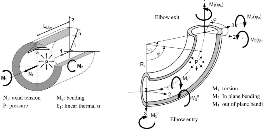
N1: axial tension
P: pressure
M2: bending
θ1: linear thermal transient
Elbow exit
Elbow entry
M1: torsion
M2: In plane bending
M3: out of plane bending
Fig 1: Loading covered by the analytical approaches for pipes and elbows
A step by step approach was started in order to cover a maximum of geometry and loading configurations encountered in nuclear vessels and piping systems. Today, it covers:
- Pipes and cylindrical shells containing circumferential or longitudinal, internal or external surface defects; - Elbows with defects in mid section, at the entry or the flank, containing circumferential or longitudinal,
internal or external surface defects;
- Tapered transitions with circumferential surface defects.
For all these structures, a large scope of potential loading was investigated: mechanical, through thickness thermal loading (temperature gradient or thermal shock) or combined mechanical plus thermal loading. Figure 1 illustrates this scope. Again, the objective of this work was and is still to cover a maximum of industrial configurations in support of defect assessment demonstrations. References [5] to [9] give the detail of the today’s available analytical solutions for pipes and elbows.
STRATEGY FOR METHODOLOGY DEVELOPMENT AND GENERAL FORMULATIONS
The development strategy initiated in 1995 for very simple cases like internal axi-symmetrical defects in pipes is still applied today for on-going developments like analytical Js in welds. The general procedure is constituted
by four major steps:
- First step is devoted to the constitution of a reference F.E. database;
- Second step is devoted to the methodology development of the new formula itself (Jsm, Jelth, kth) with
possibly complementary F.E. developments;
- Third step devoted to the validation against the reference case database;
- Fourth and final step devoted to pre-codification and presentation to the French Nuclear Safety Authority.
Reference F.E. database development
For methodology development and validation purpose, the first step of the work is the preparation of reference F.E. results. The objective is to constitute a database, commonly filed and used by the 3 partners, including both 2D and 3D results depending on the problem treated. This database is constituted step by step, starting from simple problems such as axi-symmetrical defects in pipes, up to complex cases like semi-elliptical defects in elbows. Figure 2 gives an example of one of the more complex F.E. models developed for reference case determination.
Additional reference F.E. cases developed in the frame of the CEA/IRSN actions were also developed for methodology development or complementary validations, in particular for thermal loading [10]. Today, this database contains around 2000 different cases, 2D and 3D, covering all the geometrical and loading scope codified in the RSE-M and RCC-MR fracture mechanics appendixes [1][2].
For the database constitution and for each geometrical configuration (in terms of component and defect geometry), the first step of the F.E. analysis is the validation of the F.E. model itself by a comparison of elastic-plastic J calculation results on common cases calculated by the experts of the three partners using their own F.E. code: Code_Aster (EDF software – [11]), Cast3M (CEA software – [12]) and SYSTUS (AREVA software – [13]). Aster and Cast3M software are in house F.E. codes, developed and validated internally for internal needs for more than 20 years, whereas SYSTUS is developed and maintained by ESI group then qualified by AREVA for design applications. This step, where accordance between the F.E. codes is required before the database completion, constitutes the best F.E. validation process and allows the definition of best practice for meshes, loading applications, post-treatment… Parametric models are then used in order to complete the F.E. calculation database. All the numerical analyses and results are then reported in documents and included in the F.E. database, in an imposed format, in order to allow simple extraction of the results at the validation step. CEA is in charge of the maintenance of this database.
Surface defect at the elbow entry:
Mean radius: Rm = 400 mm Thickness: t = 40 mm Elbow angle: ψψψψc = 90° Elbow parameter: λλλλ=0.4 Defect depth: a = 10 mm Defect length: 2.c = 60 mm
Fig 2: Example of F.E. model for elbows (semi-elliptical defect at the elbow exit)
General formulation
The general formulation adopted for the analytical Js calculation is based on the decomposition of elastic
and plastic contributions in the numerical scheme proposed by Ainsworth in [4]. Elastic J (or KI) is derived from
influence functions specifically developed for the purpose of codes development. These influence functions are expressed in the local stress field (polynomial fit of the stress field through the thickness of the component) in order to facilitate the transposition from one geometry to the other. Another main advantage of such formulation is to allow KI or Jel evaluations for complex geometrical configurations by a simple elastic F.E. calculation on a crack free
model. This work for KI solution development has required a huge F.E. work in order to cover a large panel of
Mechanical loading
For mechanical loading, the plastic correction to the elastic J is based on the limit load analysis and the reference stress concept initially proposed by Ainsworth in [4]. Some considerations were added in order to take into account influencing parameters such as triaxiality, interaction between mechanical loadings, stress redistribution… Analytical J, noted Js
m
, is then derived from elastic J (Jel) with the following formula:
2 r el ref ref el m s
J
.
E
.
J
J
κ
=
ψ
+
σ
ε
=
In this formula:
- εref is the strain corresponding to the reference stress σref on the true stress - true strain curve of the material
(whatever the curve shape);
- Ψ is a confined plasticity correction function of σref. In general cases, for non confined plasticity, it is
negligible in comparison to reference stress correction.
Finally, the reference stress σref is the only data required for Jsm calculation. As said previously, this term is
deduced from limit load analysis and thus includes the evaluation of the global plasticity in the structure and should also consider the presence of the defect. Two methods are proposed in the codes for that purpose. They rely either on a limit load formula expressed in terms of global mechanical loading (CLC option) or an elastic plastic reference stress determine on the remaining ligament (CEP option). These two options are developed in parallel, allowing benchmarks, emergence of different point of view or understanding, giving at the end equivalent results but with a slightly different validity domain. These two options are presented in [1][2] and ref. [5] to [9].
Thermal loading
For thermal loading, it is no more possible to rely on limit load analysis to define a reference stress and a plastic correction. In addition, many numerical simulations showed the possible attenuation of J parameter due to plasticity: Jsth could be smaller than Jelth. This phenomenon, linked to the attenuation of stresses under imposed
strains for elastic-plastic material behavior, is explained in detail in [10] and can be summarized as follows:
- Thermal transient, and in particular through thickness thermal gradient, corresponds to an imposed strain. In that case elastically determined associated stresses overestimate the real stresses which are reduced by plasticity. Elastic J must be reduced in order to take into account this plasticity effect.
- On the contrary, plasticity in the cracked section and potential elastic follow-up between cracked and un-cracked section can also amplify the elastic J, as it is the case for mechanical loading.
The kth coefficient multiplies these two corrections and eventually an interaction with mechanical loading
(kth *
coefficient). However, in the general case, kth or kth *
are smaller than 1 since the thermal stress reduction correction is dominating. The general J formulation for combined thermal and mechanical loading is finally the following: 2 th el * th r m el 2 th el * th m s th m
s
k
.
J
J
J
.
k
J
J
+
κ
=
+
=
+ .In this formulation, contribution from mechanical loading is not affected by the thermal loading. On the contrary, the contribution of the thermal loading is affected, and the related ‘relaxation’ due to the plasticity is more or less decreased in function of the intensity of the mechanical loads (is some extreme cases, kth* can be higher than
one). One can notice that this formulation is drastically different from the R6 rev 4 [16] formulation which could be approximated, in our notations as follows:
2 r th el m el th m s
J
.
V
J
J
κ
+
≈
+ ,where V is a correction factor applied to the secondary loading and κr is the ‘reference stress based’
Residual stresses consideration
Residual stresses where not initially considered in the analytical developments since major scope of the methodology development is vessel and piping systems made of high ductility materials. In that case, residual stress field influence on tearing initiation and propagation is assumed to be negligible. However, in order to justify that position and to extend the applicability of the approaches to low ductility materials, the question of residual stresses is more and more discussed. In the frame of analytical Js development, this question is a complex one since:
- The methodology development is mainly based on the constitution of reference F.E. results. But how to develop these F.E. results? In particular, how to impose a ‘physical’ residual stress field in a F.E. model? - Residual stresses are considered as secondary stresses, imposed prior to the other loading. But what is the
effect of the crack on its distribution? How to take interaction between primary stresses and those residual stresses.
In a first approach of the problem, the residual stresses were considered as an initial strain field imposed via an initial thermal transient. This approach can be applied in both F.E. analysis and analytical scheme. However, this position is not definitive today since the R&D group devoted to analytical J development is still working on that topic.
Illustration of the A16/RSE-M5.4 pertinence through an example
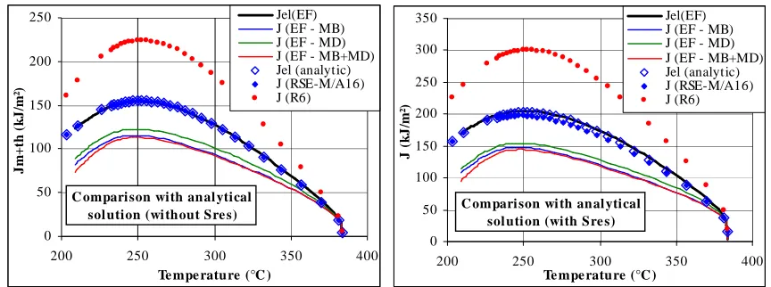
The example presented in this chapter corresponds to a large cladded ferritic vessel, containing an axi-symetrical defect in the symmetry plane of a circumferential narrow gap weld joint and submitted to a pressurized thermal shock. The chosen geometrical and loading configurations are described in next figure.
Material data used for the calculation are those of RCC-M code and corresponds to low alloy steel and associated weld metal (physical and mechanical parameters depending on temperature). The cladding is taken into account only for température calculation.
Tfluid
time Th
Tc
tshock
ri = 1410 mm
h = 140 mm hw = 30 mm
a = 30 mm
P = Cte = 16.67 MPa Th = 383.3°C
Tc = 100°C
tshock = 1s
h ri
a
hw/2
Fig 3: Geometry and loading description
For this configuration, two approaches are used in order to determine J:
- F.E. modeling. In that case, three different calculations are performed: considering base metal only (MB), considering weld metal only (MD) or considering both materials (MB+MD).
- Analytical solution. In that case, a purely analytical solution exists in the A16/RSE-M5.4 appendixes if physical and mechanical parameters are assumed constant with temperature. In order to maximize stresses, the code recommends choosing those material parameters at the lowest temperature.
The following comments should be added in order to complete the description of the application:
- Two cases are treated: without or with residual stresses. In that last case, residual stresses are imposed via an initial thermal gradient, equilibrated through the thickness and creating a constant stress field close to the inner surface where the defect is located. Stress level: is σres = 67 MPa.
- In A16/RSE-M5.4 application, kth coefficient is determined via the simplest and more conservative option 1
(explicit formulation of kth) and using weld metal yield stress.
- Similarly, simplified V option for secondary loading is used in the R6 application.
- Elastic analytical J is the same for the two simplified applications. The difference in the methodology is only at the plastic correction level.
- As expected for that cases dominated by thermal loading, F.E. elastic J is higher than elastic-plastic J. The difference in material behavior is not significant since the difference in yield stress between base metal and weld metal is not important.
- Elastic J predicted by the analytical approach is in good accordance with or without residual stresses. This is due to the fact that, for that simple geometry and loading configuration, the analytical solution is quasi-exact: the only approximation, not significant, is to consider constant physical parameters.
- Plastic correction anticipated by the A16/RSE-M5.4 is equal (with residual stresses) or slightly lower (without) than 1. This constitutes a conservatism which is mainly due to the use of weld metal yield stress of the kth determination.
- At the opposite, plastic correction anticipated by R6 via V parameter is significantly larger than one. Consequence is a large over-conservatism of J (around a factor of 2 on maximum J).
0 50 100 150 200 250
200 250 300 350 400
Te mpe rature (°C )
J
m
+
th
(
k
J
/m
²)
Jel(EF) J (EF - MB) J (EF - MD) J (EF - MB+MD) Jel (analytic) J (RSE-M/A16) J (R6)
C ompari son with anal ytical sol ution (wi thout Sre s)
0 50 100 150 200 250 300 350
200 250 300 350 400
Te mpe rature (°C )
J
(
k
J
/m
²)
Jel(EF) J (EF - MB) J (EF - MD) J (EF - MB+MD) Jel (analytic) J (RSE-M/A16) J (R6)
C ompari son wi th anal ytical sol uti on (with Sre s)
Fig 4: Comparison between analytical and F.E. results
VALIDATION STRATEGY
Validation phase is an important one in terms of presentation and acceptability of the formula by the Safety Authority. Approaches become more and more sophisticated and an illustration of their pertinence and conservatism through comparison to reference cases is needed.
At the opposite of R6 strategy [16], the working group choice was to develop a specific ‘validation set of reports’. These validation reports are not included in the code: this is not French practice and due to the large number of validation cases, this set would be too large. This ‘validation set of reports’ is re-edited regularly, including new reference data, new developments or methodologies, corrections…: the one for mechanical loading in 2006, the one for thermal loading in 2011.
Another major difference with R6 rule is that the validation of the J analytical schemes is performed against F.E. results and not tests. We consider the validation against experimental data as non appropriate for the J analytical scheme for the following main reasons:
- The direct comparison to tests globally includes a lot of uncertainties (loading knowledge, criteria validity, material data, measurement…) and do not allow the identification of their influence separately. Everything is mix together so that it is very difficult to detect any under or over-conservatisms.
- This aspect is particularly true in a
κ
r-Lr representation where a subjective choice has to be made for thedefinition of the point positions in the diagram:
o What formula to define Lr? What is the reference yield stress for this Lr definition? Large uncertainty, in particular for weld joints.
o What value of KIC for κr determination (mean or minimum value)? Fundamental choice for
brittle fracture, but also for ductile fracture.
o What about the transferability of criteria? Brittle fracture criteria are known to be sensitive on constraint and JR-∆a curve is known as very conservative when applied to structures. This
over-conservatism could hide any under-over-conservatism of J evaluation scheme.
o For thermal loading, the Js formulation has a direct impact on the κr definition (see previous
- On the contrary, the strategy defined for the fracture mechanics appendixes of RSE-M and RCC-MR codes is to separate the overall criteria in two sub-problems: In the validation strategy we considered, the analytical tool are directly validate one-by-one by a comparison with F.E .reference solutions to guaranty a systematic conservative result, and the experiments are used only to validate the fracture criterion included in the RSE-M and RCC-MR codes. In other words, for a criterion expressed as follows:
Js(Load, Geometry, Material) = JIC(material),
two separate validations sets are developed:
- On one hand, the analytical Js formulation is to be validated against reference numerical data. A maximum
of loading configurations, structural and defect geometries, materials… are investigated in that frame. For some difficult geometry, this validation could also be separated in 2 parts: KI and reference stress validation.
This is the work performed by the Js working-group.
- On the other hand, the criterion validity is checked against experimental data, in particular via tests on specimen and structures with the objective to evaluate the possibility to predict fracture on the structure based on data fitted on specimen. In major cases, imposed J values are determined via F.E. modeling, validated against experimental data, in order to avoid a potential lack of precision of an analytical J.
For analytical J, CEA is in charge of this the validation. To do so, CEA has developed in cooperation with IRSN specific software [17] devoted to fracture assessment approaches codified in the RCC-MR A16 appendix. A dynamic link between the software and the reference database is possible so that a systematic comparison between analytical and F.E. solutions is possible.
TODAY’S STATUS AND ON-GOING WORK
Current version of the FMA appendixes of RSE-M [1] and RCC-MR [2] include the methodology for Js
calculation in pipes and elbow. In that scope, a large panel of loading, defect geometry, size and position is available for mono-material configurations. Both mechanical and thermal loading (smooth transients and thermal shocks) are covered by the proposed formulations. Recently, a new formulation of analytical Js was developed, discussed with the safety authority and included in the 2010 edition of the RSE-M. This formulation covers today homogeneous weld joints in pipes submitted to mechanical loading. For the complement of these available solutions, the on-going or future work is focused on the following actions:
- The complement of the homogeneous weld joint solution for thermal loading. - The evaluation of Js with a residual stress field.
- A re-actualization of the validation set (systematic comparison of the Js formulation to the reference F.E.
database).
- Preparation and animation of a benchmark on Js analytical schemes.
This last point is currently going-on within the frame of the OECD/CSNI/IAGE working group on structural integrity. Its objective, detailed in the benchmark specification [18], is to compare the different analytical formulations available in OECD countries to a set of F.E. reference solutions: around 50 cases including pipes and elbows submitted to mechanical and thermal loading.
SYNTHESIS AND CONCLUSIONS
This paper summarizes the large effort performed in France in support of defect assessment methodology included in fracture mechanics appendixes of RSE-M and RCC-MR codes. Initiated in the 90s in partnership between CEA/EDF/AREVA a completed by cooperative CEA/IRSN R&D actions, the analytical approaches developed in that program for J parameter calculation covers now a large scope of geometry, defects sizes and positions, loading cases…
A particular focus on the background and the strategy is proposed in the paper. It describes in particular the step by step procedure, the choices made for general formulation and validation. Main headings of the presentation are the following:
- Constitutions of a reference F.E. database;
- General formulation for J calculation, for mechanical and thermal loading; - Validation strategy;
In this presentation, general comparisons to the R6 rules are proposed in order to highlight main similitude and divergences. It is then shown that:
- For mechanical loading, the same general formulation based on reference stress concept was adopted in R6 and A16/RSE-M5.4 fracture mechanics appendixes.
- For thermal loading, the formulations are different. It is shown with an example that he R6 ones, which amplifies the contribution due to thermal loading, is very conservative in comparison to evolutions observed in F.E. analyses.
- The Validation strategy is also different, with a choice of a ‘validation set’ exclusively based on comparison to reference F.E. solutions for the analytical tools (i.e. fracture mechanics parameter calculation), and use of experimental results only for the criteria validation for the A16/RSE-M5.4 codes, and a global comparison to tests included in the code for R6.
REFERENCES
[1] 5.4 appendix of the RSE-M, 2007 edition [2] A16 appendix of the RCC-MR, 2007 edition
[3] Kumar V, German MD, Shih CF. An engineering approach for elastic–plastic fracture analysis. EPRI-NP-1931, Project 1287-1, Topical Report, Electric Power Research Institute, Palo Alto, CA, 1981
[4] Ainsworth R.A., The assessment of defects in structure of strain hardening material, Engineering Fracture
Mechanics, 19 (1984), n°4, pp 633-642
[5] S. Marie et al., French RSE-M and RCC-MR code appendices for flaw analysis: Presentation of the fracture parameters calculation - Part I: General overview, International Journal of Pressure Vessels and Piping 84
(2007) 590–600
[6] S. Marie et al., French RSE-M and RCC-MR code appendices for flaw analysis: Presentation of the fracture parameters calculation – Part II: Cracked plates, International Journal of Pressure Vessels and Piping 84 (2007)
601–613
[7] S. Marie et al., French RSE-M and RCC-MR code appendices for flaw analysis: Presentation of the fracture parameters calculation – Part III: Cracked pipes, International Journal of Pressure Vessels and Piping 84
(2007) 614–658
[8] S. Marie et al., French RSE-M and RCC-MR code appendices for flaw analysis: Presentation of the fracture parameters calculation – Part IV: Cracked elbows, International Journal of Pressure Vessels and Piping 84
(2007) 659–686
[9] S. Marie et al., French RSE-M and RCC-MR code appendices for flaw analysis: Presentation of the fracture parameters calculation – Part V: Elements of validation, International Journal of Pressure Vessels and Piping
84 (2007) 687–696
[10] S. Chapuliot and M. Nédélec, Analytical method for the calculation of J parameter on cracked pipes under thermal loading and mechanical plus thermal loading, PVP2002
[11] www.code-aster.org
[12] NEER-F DC 10296 : Progiciel SYSTUS : note de synthèse de vérification et de validation physique. [13] www-cast3m.cea.fr
[14] S. Chapuliot: Formulaire de KI pour les tubes comportant un défaut de surface semi-elliptique longitudinal ou
circonférentiel, interne ou externe. Rapport CEA-R-5900 (2000)
[15] S. Marie and S. Chapuliot: Improvement of the calculation of the stress intensity factors for under-clad and through clad defects in a reactor pressure vessel submitted to a pressurised thermal shock, International Journal
of Pressure Vessels and Piping 85 (2008) 517– 531
[16] R6 – ‘Assessment of the integrity of structures containing defects’, Revision 4 April 2001. British Energy. [17] MJSAM: an original PC software based on the A16 guidelines for defect assessment, Materials at high
temperature 15 (1998), n° 3-4, pp. 357-362
[18] S. Marie & C. Faidy: BENCH-KJ – Benchmark on the analytical evaluation of the fracture mechanic parameters K and J for different components and loads. Description of all the different cases, OECD/CSNI/IAGE,