EXPERIMENTAL DATABASE OF SC COMPOSITE SPECIMENS
TESTED UNDER OUT-OF-PLANE SHEAR LOADING
Kadir C. Sener1, Amit H.Varma2, Sanjeev R. Malushte3, and Keith Coogler4
1 Ph.D. Candidate, School of Civil Eng., Purdue University, West Lafayette, IN ([email protected]) 2 Assoc. Professor, School of Civil Eng., Purdue University, West Lafayette, IN ([email protected]) 3 Bechtel Fellow and Sr. Prin. Engineer, Bechtel Power Corp., Frederick, MD, ([email protected]) 4 Sr. Structural Eng., Westinghouse Elec. Corp, Cranberry Township, PA ([email protected])
ABSTRACT
Steel-concrete composite (SC) walls of safety-related nuclear facilities are subjected primarily to in-plane shear forces and gravity loads. They are also subjected to out-of plane shear and bending demands near foundations regions and connection regions at locations where they potentially interfere with other structures. The out-of-plane behavior of SC walls is expected to be similar to the behavior of reinforced concrete (RC) walls. The out-of-plane behavior of SC walls was evaluated by conducting beam tests by subjecting to one-way bending that were representative of a large scale wall stripes taken in the longitudinal and transverse directions. This paper includes a summary of the experimental database developed by previous SC beam tests conducted in Japan, South Korea and the United States. Results of the experimental investigations including the comparisons with the applicable design codes of each country are presented.
INTRODUCTION
SC walls are being used in current nuclear power plant designs, and they are being considered for future small modular reactors. SC walls are being considered as a suitable replacement for RC walls in safety-related nuclear facilities. Out-of-plane shear demands in these structures are generally observed at structural discontinuities such as regions adjacent to large openings or at the base of the shell structure. Typical loading condition to generate out-of-plane shear forces are from internal pressure or temperature gradients through the wall thickness. These types of shear forces are carried through the thickness (out of plane) of the walls, which permits testing of SC beams to determine their out-of-plane shear strength.
SC walls are widely used in current nuclear power plant construction projects. In general, SC walls are being substituted for walls that where historically made out of reinforced concrete or pre-stressed concrete. The motivation for using SC walls comes from the fact that the erection and construction of SC walls are faster than traditional reinforced concrete construction. The usage of SC walls with steel faceplates on the exterior surfaces can significantly reduce rebar congestion, and also assure efficiency during concrete placement when used with self-consolidating concrete.
The mechanism for carrying out-of-plane shear for SC walls are similar to reinforced concrete beams but with a number of significant differences. The main contributors to the out-of-plane shear resistance are: (i) the concrete infill between the two steel plates on the sides, (ii) shear reinforcement if provided, and (iii) shear studs. The steel faceplates have a secondary influence, but can govern the out-of-plane failure mode (i.e., flexural or shear failure). It is also important to note that the shear stress acting through the depth or wall thickness in the transverse direction on a beam has to be in equilibrium with the longitudinal (interfacial) shear stresses.
that are anchored into the concrete infill. The tests were conducted under different out-of-plane loading configurations. Other the parameters used in these tests were: shear span-to-depth ratios, steel plate reinforcement ratios, stud and tie bars reinforcement ratios.
The objectives of this study are to provide information about the SC wall out-of-plane shear and flexural strength tests intended for nuclear power plant applications and to compare the test results with the applicable design codes that are used in each country.
CURRENT SC DESIGN PRACTICE FOR OUT-OF-PLANE LOADING
Current design codes address shear strength of concrete beams with either mechanics based equations, or purely empirically based equations. Code requirements addressing directly SC structures are available only in Japan (JEAC-4618-2009) and South Korea (KEPIC-SNG). The Japanese and Korean codes’ out-of-plane shear strength equations were developed based on experimental tests conducted in those respective countries which will be discussed in the upcoming sections. The SC structure design practice in the United States uses the ACI code provisions for nuclear concrete structures (ACI 349), which are mainly developed towards reinforced concrete structures.
DESIGN PRACTICE IN THE US
Out-of-plane Shear Strength
ACI 349 code provisions for shear strength of reinforced concrete beams that are subjected to shear and flexure only are summarized using Equations 1 through 3. In these equations the nominal shear strength (Vn) is given as the summation of two parts where Vc is the shear strength contribution of the concrete and Vs is the shear strength contribution from the shear reinforcement such as using a deformed bar or wire reinforcement.
s c n
V
V
V
=
+
Equation 1c u u w c
c
f
V
M
d
A
V
⋅
+
=
1
.
9
`
2500
ρ
(psi) Equation 2s T F A
Vs = v⋅ y.sh⋅ Equation 3
In these equations; f’c is the compressive strength of concrete, ρw is the longitudinal tensile reinforcement ratio, Vud/Mu is the depth to shear span ratio term, Ac is the cross-sectional area of concrete,
Fy.sh is the yield strength of the vertical shear reinforcement, Av is the cross-sectional area of shear reinforcement, T is the section depth, and s is the shear reinforcement spacing. The Vc equation is applicable to beams that have shear span-to-depth ratios (a/d) larger than 1.0 and also with an upper bound stress of 3.5√ f’c in psi. The simplified and more commonly used version of the shear strength formulation is given as 2√ f’c in psi. The spacing limit to take the shear reinforcement accounted in the design strength is to have at most half-of-depth (T/2) distance between the reinforcement elements.
Out-of-plane Flexural Strength
trapezoidal, (vi) usage of equivalent rectangular uniform concrete stress distribution equal to 0.85 f’c. The listed assumptions can be applied to SC walls as long as they meet the requirements and limitations that the assumptions are based on.
SC design have equal longitudinal reinforcement on either side so inherently similar to a doubly reinforced concrete beam. Hence, it is expected that yielding of the compression steel plate not to occur since this would violate the force equilibrium in the section unless concrete is fully crushed. Therefore this limits the strain level in the compression extreme fiber of concrete to the yield strain of steel. Typically used steel plates in this type of walls have a yield strain of about 2000μ. This strain level is similar to the concrete strain that corresponds to its compressive strength (f’c), which concrete stress variation can be approximately be assumed as linear up to this strain level.
Using the discussions and assumptions stated above; by transforming the compression steel plate into an equivalent rectangular concrete block and assuming a triangular stress variation in concrete below this level can lead to the derivation of Equation 4. The stress variation in the transformed concrete block is assumed to be constant due to steel plates having small thicknesses and equal to f’c. In the proposed equation, the section moment is calculated by summing moments about the centroid of the transformed concrete block (centroid of the compression plate).
(
)
+ ⋅ ⋅ − − ⋅ ⋅ = 2 3 ' 2 1.pl p c c c p
y pl n t c c b f t T F A
M Equation 4
⋅
−
⋅
⋅
⋅
=
p c pl y plc
f
b
n
t
F
A
c
'
2
. Equation 5In the above equations; cc is the depth of the triangular concrete compressive stress block, Apl is the cross-sectional area of the steel plate on one side, tp is the thickness of the steel plate, Fy.pl is the yield strength of the steel plate, T is the section depth, b is the section width, and n is the modular ratio and calculated as the elastic modulus ratio of steel to concrete.
DESIGN PRACTICE IN JAPAN
Out-of-plane Shear Strength
A strength equation is proposed for the out-of-plane shear strength of SC members by JEAC-4618 (2009) based on the test results obtained by Takeuchi et al. (1999). The allowable concrete shear strength equations under sustained loading are derived as a collection of several different strength contributor mechanisms. These mechanisms include the shear force that is carried by the cracked surface (Qw), the shear strength contribution by arch mechanism (Qarch), and finally the shear strength contribution by truss mechanism (Qbond).
Due to the lack of test data on beams with shear reinforcement, the JEAC code does not account for shear reinforcement in the design strength unless it is more than 0.2%. The equation for unreinforced design which also governs for most of the shear reinforced beam cases is shown in Equation 6. The shear strength for beams with shear reinforcement is more complicated and involves six equations listed from Equation 7 to Equation 12. The limitations on certain parameters are also given with the equations.
T
b
f
V
c.JEAC=
0
.
32
⋅
'
c⋅
⋅
Equation 6(
)
(
)
(
c w arch bond)
JEAC s
c
f
b
T
Q
Q
Q
V
+.=
max
0
.
32
⋅
'
⋅
⋅
,
min
,
0
.
8
⋅
+
Equation 7(
)
(
f
b
T
f
b
T
)
Q
w=
max
0
.
31
⋅
'
c⋅
⋅
,
2
.
8
⋅
ρ
w⋅
w t 23⋅
⋅
,(
f
)
MPa
t w
w
⋅
max=
2
ρ
Equation 8T b f
Qarch = 91
λ
⋅ν
2⋅ 'c⋅ ⋅ Equation 9λ
ν
2=
0
.
8
+
0
.
05
⋅
Equation 10T b B
Q
Q ST u
bond =0.45⋅ 2 ⋅ ⋅ Equation 11
c c sc
u
ST
Q
=
0
.
5
⋅
a
⋅
f
'
⋅
E
,(
f
'
c⋅
E
c)
max=
880
MPa
Equation 12In the above equations; sca is the section area of the stud, B is the stud spacing, stQu is the shear strength of one stud, Qbond is the shear strength by truss mechanism, Qarch is the shear strength by arch mechanism, Qw is the shear force determined by the shear transfer limit of a cracked surface, ν2 is the effectiveness factor for concrete compressive strength, T is the section depth, b is the section width, and λ
is the shear span ratio that the lower bound is 1.0 and the upper bound is 3.0.
Out-of-plane flexural strength
The SC design code of Japan (JEAC) addresses the out-of-plane bending moment of SC walls with the plastic moment capacity equation given in below,
T F
A
Mn = pl⋅ y.pl⋅87 Equation 13
In Equation 13, the flexural strength is calculated by simply assuming the lever arm between the centroid of the tension plate and the compression force resultant occurs at a distance of 87.5% of the section depth.
DESIGN PRACTICE IN SOUTH KOREA
Out-of-plane shear strength
A similar mechanics based strength equation is proposed for the out-of-plane shear strength of SC members by KEPIC-SNG based on the previous Japanese experimental research and also the tests conducted by Hong et al. (2009). The Korean design practice utilize the shear strength contribution from the cracked section (Vcr.SNG) and the arch mechanism (Var.SNG), however does not use the truss mechanism. The shear reinforcement contribution to the shear strength (Vs.SNG) is accounted in the design strength only if the shear reinforcement ratio is larger than 0.2% similar to the JEAC code, but it is considered in a manner that is following the ACI approach.
SNG ar SNG s SNG cr SNG
n
V
V
V
V
.=
.+
.+
. Equation 14T
b
f
V
cr.SNG=
0
.
16
⋅
'
c⋅
⋅
Equation 15T b F
(
)
[
]
f b TVar.SNG = 12⋅ 4⋅
φ
⋅1−φ
+λ
2 −λ
⋅ν
2⋅ 'c⋅ ⋅ Equation 17T
a
f
c avg'
µ
φ =
Equation 182
B Vua avg =
µ
Equation 19u cr
p ua
I
B
V
Q
V
=
⋅
⋅
Equation 202 05 . 0 8 . 0 2
λ
ν
= + ⋅ Equation 21In the above equations; ϕ is defined as the ratio of the stud bonding strength to the concrete compressive strength, where μavg is the bonding strength of stud. Additionally, Vua is the required shear strength of a single stud, stud spacing, Qp is the first moment of area about the centroidal axis of crack transformed cross-section, Icr is the moment of inertia of crack transformed cross-section, B is the section width, Vu is the required out-of-plane shear strength for the width of B, a is the shear span length, and λ is the shear span ratio that the lower bound is 0.5 and the upper bound is 6.0.
Out-of-plane flexural strength
The SC design code of Korea (SNG) addresses the out-of-plane bending moment of SC walls with the plastic moment capacity equation as given in below. The Korean flexural strength equation also addresses the attachment elements that are connected to the steel plate, since these members can have significant influence on the flexural strength. Furthermore, the equation also accounts for the potential reduction of the compression plate contribution to the flexural strength due to local buckling.
(
) (
)
yrib rib ribc cr pl y p p pl cr yp p pl cr
n
f
F
A
d
F
F
t
t
T
A
F
F
t
T
A
F
M
+
⋅
⋅
⋅
−
⋅
⋅
−
⋅
−
⋅
−
+
−
⋅
=
. .'
85
.
0
5
.
0
5
.
1
Equation 22pl y pl y n p p
cr t F F
B K
F 1.5 0.043 90 ⋅ . < .
⋅ − ⋅ ⋅ −
=
ε
Equation 23cs n
=
0
.
002
⋅
C
ε
Equation 24In the above equations; Fy.rib is the yield strength of the attached (rib) sections, Arib is the area of the rib section, and drib distance between the centroidal axes of ribs on both sides. Fcr is the local buckling strength of surface steel plate which is calculated in Equation 23, where Kp is given as the effective buckling length factor of surface steel plates and is recommended to be equal to 0.5, εn is defined as the nominal compressive strain which is a function of a creep and shrinkage constant (Ccs) that is taken equal to unity since time dependent factors are not considered in this study.
EXPERIMENTAL DATABASE
are anchored into the concrete infill have been tested under different out-of-plane loading configurations. The parameters used in these tests were: shear span-to-depth ratios, steel plate reinforcement ratios, stud and tie bars reinforcement ratios.
In total, 48 experimental tests to study the out-of-plane behavior of SC walls. Shear reinforcement of some sort have been provided on 32 of the specimens in the database. Failure modes of the tested specimens were determined based on three methods listed below:
• By studying the strain data of the steel plates and the shear reinforcement. ‘Shear failure’ was considered to be achieved if the strain levels in the shear reinforcement were in excess of the material’s yield strain. On the other hand, excessive yielding in the steel plates were indicator of ‘flexural failure’. If both the above cases occurred and the specimen had a peak load and a load drop following it then this failure mode was placed under ‘flexural-shear failure’ category.
• If the strain data was not available, then the load vs. vertical displacement curve of the specimens were investigated. The failure mode was determined based on the slope of the portion that a significant stiffness change occurs in the curve. For example, a negative stiffness in the post-peak load region is an indication of shear failure; on the other hand, a positive stiffness most of the times results from longitudinal reinforcement yielding therefore considered as flexural failure.
• Design formulations that are proposed to estimate the shear and flexural strength capacities can be useful to determine the governing failure mode if there is a significant difference in the strengths calculated for the individual failure modes. This method may not be so accurate to determine the failure mode if calculated shear and flexural strength values are in similar magnitude.
The specimens in the experimental database were categorized per the failure modes being ‘shear’ and ‘flexure’ based on the methodology stated above. The specimens under ‘flexural shear’ category are included in both ‘shear’ and ‘flexural’ failure categories because these tests provide essential information for both tests. In fact, the flexural-shear type failure has shown to give the lower bound shear strength so that it is more valuable in confirming the applicability of the design code equations.
Four loading patterns (a), (b), (c), and (d) that have been used to conduct the experiments. ‘Loading type a’ is a two-point support four-point loading configuration, and ‘Loading type b’ is an anti-symmetric loading configuration. These loadings simulate rotational fixity at support locations. Loading Types c and d are simple three and four point bending configurations and the shear span is measured by the distance from the load point to the nearest support.
SC beams tested in Japan
Ozaki et al. (2001) have tested 16 SC beams that had combinations of shear studs and round tie bars anchored to concrete. The specimens had shear span-to-depth ratios mostly less than 1.5 except three of the specimens. The steel faceplate reinforcement ratios varied from 1.33% to 4%, calculated based on the total steel area in the cross-section. The compositeness factor which is defined as shear stud spacing to steel plate thickness (s/tp) varied from 22 to 44.
Loading configurations a, b, and c were used for testing the beams. The experimental program included six specimens having shear reinforcement with round bars and two of these specimens did not have any shear studs. Out of the 16 specimens; 13 of them failed in shear and 3 in flexural yielding.
SC beams tested in South Korea
Similar to the Japanese test program the composite action factor (s/tp) varied from 22 to 44. The specimens were subjected to loading configurations b and c. Shear reinforcement was provided by means of round deformed bars on all the specimens except one not having any. However, for most of the specimens the shear reinforcement spacing exceeded the ACI code limitations (T/2) to be accounted in the design strength. Therefore, although most of the specimens had shear reinforcement, only one specimen had a spacing that conformed the spacing limit and utilized the design strength contribution from the reinforcement when calculated based on the ACI equation. The Japanese and Korean codes did not specify any spacing limitations.
This testing series had relatively larger shear span-to-depth ratios with most of the specimens at 3.6, which were tested in loading configurations b and c. In this nine specimens, the influence of having shear studs, tie bars, and ribs which are, H shaped steel sections that are continuously welded to the inner faces of the steel plates in the longitudinal direction, were also studied while maintaining the overall geometry and the a/d ratio constant.
In this experimental program of 13 specimens, a more uniform distribution in failure modes occurred due to having larger shear span-to-depth ratios compared to the Japanese program, where 5 specimens failed in shear, 4 in flexure and 4 in flexural shear.
SC Beams Tested at Purdue University
An experimental test program was carried out at Purdue University’s Bowen Laboratory for Large-Scale Civil Engineering Research that emphasizes mainly towards obtaining the lower bound shear strength for SC beams. A total of 19 well instrumented simply supported SC beams were tested in loading configurations c and d with specimens including both small scale and large scale tests.
The experimental program consisted of two specimen groups to study the influence of shear reinforcement more clearly. The first specimen group did not have any shear reinforcement. The second specimen group was sub-divided into three different groups based on the reinforcement types as; round tie bars, steel plates and structural steel channel sections.
The first group (T.S.1) had five specimens having headed shear studs anchored to concrete and without any shear reinforcement. The specimens were designed so that in each test only one parameter was changed. By keeping the rest of the properties unchanged from the reference small-scale specimen having 18 inches section depth (SP1-1). The parameters varying in this test group include the stud spacing (SP1-2), plate reinforcement ratio (SP1-3), shear span-to-depth ratio (SP1-4), and specimen scale ratio (SP1-5). The shear span-to-depth ratios for this specimen group varied from 2.5 to 3.5.
In the second specimen series, 14 large-scale out-of-plane shear tests were conducted to evaluate the effects of including shear reinforcement. In addition to having shear studs, the specimens in Test Series 2a had round bars (4 sp.), Test Series 2b had steel plates (4 sp.) and Test Series 2c had channel sections (6 sp.) as shear reinforcements that are connecting the faceplates on both sides by being welded to the steel plates. Test Series 2a specimens had identical cross sections, round tie bar and stud properties but had different shear span-to-depth (a/d) ratios of a specimen at 2.5, two at 3.5, and one at 5.5.
Test Series 2b specimens had angle sections fillet welded to the inner face of the steel faceplates. The angles are then connected by channel sections along the length of the specimen. The first two specimens had same section depths and identical stud layout but having different angles orientations. The shear reinforcement spacing was at a section depth (T) distance for SP2b-1 and was 1.5T for SP2b-2. SP2b-3 and SP2b-4 were identical to the first two specimens other than having the section depth of 1.5 times of them. Therefore for all the specimens in this group the channel shear reinforcement spacings exceeded the limits in the ACI code (T/2).
yielding. Specimens SP2c-3 and SP2c-4 were tested at a/d equal to 3.0, to observe flexural-shear type failure. The last two specimens (SP2c-5 and SP2c-6) were intended to investigate the flexural strength.
In summary; out of a total 19 specimens tested at Purdue University, 9 failed in shear, 6 failed in flexure and 4 failed in flexural shear.
Experimental Results of the SC Database
The maximum shear force and bending moment values obtained from the experiments for all 48 specimens presented above are normalized with the calculated shear or flexural strengths based on the failure mode. The shear and flexural strengths are calculated using the ACI approach and the equations provided in JEAC and SNG. The strength capacities are compared with the code equations with respect to the shear span-to-depth ratio and the section depth to study the variation trends.
In the experimental database; 27 specimens failed in shear and 8 specimens in flexural shear. One of the specimens (SP1-2) that failed in shear was due to horizontal shear failure rather than vertical shear failure. The horizontal shear failure was due to large stud spacing and not having any sufficient elements to transfer the horizontal shear. Therefore, that specimen was excluded in the plots and the remaining 34 specimens are considered in the plots.
Flexural yielding was observed in 13 specimens in the database. In addition to those specimens, the 8 specimen failed in flexural shear also were included in the plots to study the performance of the design equations.
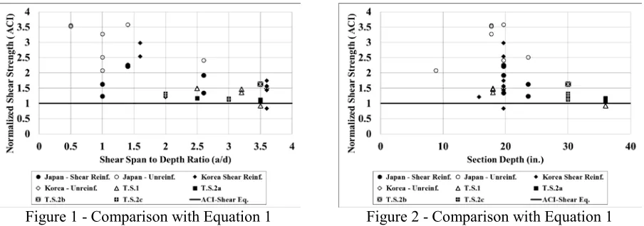
Comparison with the ACI approach
The shear strengths obtained from specimens tested in Japan, South Korea and at Purdue Uni. are shown in Figure 1 by being normalized with nominal ACI shear strength equation (Equation 1) and while varying with shear span-to-depth ratios (a/d). The specimens are categorized based on the test groups and the shear reinforced specimens are shown with filled markers. It is seen that there is a clear trend in the plot where the increase in shear span to depth ratio results in a decrease in the strength of both reinforced and unreinforced specimens. Although the equation has Mu/Vud term to account for this, it has fallen short in estimating this parameters influence on the overall strength. The lower bound shear strength is observed to be occurring when the a/d ratio is about at 3.0~3.5 range.
Figure 1 - Comparison with Equation 1 Figure 2 - Comparison with Equation 1
scale specimens for this type of thick walls. However it is not common practice to have unreinforced walls, since in actual SC wall design shear reinforcement of some kind is almost always provided.
Figure 3 - Comparison with Equation 4 Figure 4 - Comparison with Equation 4
Similar plots are shown for the flexural strengths that are normalized with the flexural equation (Equation 4) that is derived per the assumptions that ACI 349 recommends. As shown, the flexural strength equation adequately estimates most of the specimen capacities. It is also observed that there is not a clear trend between the flexural strength and neither the a/d ratio nor the section depth.
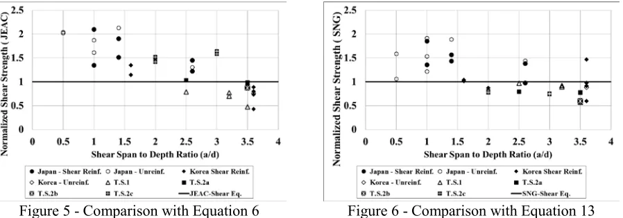
Comparison with JEAC and SNG code equations
The Japanese and Korean code equations are compared with the test results in the figures below based on the failure modes. Figure 5 and Figure 6 show the comparisons for the shear strength with the JEAC and SNG codes, respectively. In the shear strength comparison, the JEAC code equation significantly overestimates the lower bound shear strength region where a/d is greater than 3.0. Although the overall Vtest/Vcalculated average for this equation is 1.26, this average becomes 0.96 for specimens having
a/d larger than 2.5 and becomes 0.91 for specimens with a/d larger than 3.0. Similar outcomes can be listed for the SNG code equations for its shear strength estimation since for the lower bound shear strength range the code equations are providing un-conservative estimates.
Figure 5 - Comparison with Equation 6 Figure 6 - Comparison with Equation 13
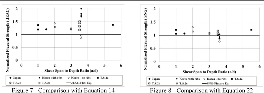
Figure 7 - Comparison with Equation 14 Figure 8 - Comparison with Equation 22
CONCLUSIONS
An experimental database including total of 48 SC beam tests has been compiled and studied to investigate the behavior while subjected to out-of-plane shear loading. The specimens had parameters including; loading configuration, section depth (T), steel plate thickness (ts), shear span-to-depth ratio (a/d), longitudinal reinforcement ratio (2ts/T), inclusion of shear reinforcement, and spacing of shear studs/shear reinforcements.
The shear strength equations in the Japanese and the Korean code overestimates the shear strength of SC beams due to basing the equations to beam shear tests that were tested in low shear span-to-depth ratios where D-region affects were significant to result in a higher bound strength. In the JEAG code the way shear reinforcement is taken into the shear strength is also limited due to the lack of test data. The flexural strength equations recommended in these codes provide a conservative estimate for the most part of the experimental database.
The experimental results indicate that the ACI code equations for reinforced concrete members can be used to estimate the lower bound out-of-plane shear strength of SC beams with or without shear reinforcement. The code equation has shown to be providing a conservative prediction for the big majority of the specimens. The flexural strength also has shown to be underestimating the bending moment capacity but with low accuracy for the specimens with ribs since the attachments are not considered in the flexural strength equations.
REFERENCES
ACI 349 (2006), “Code Requirements for Nuclear Safety-Related Concrete Structures and Commentary,” American Concrete Institute, Farmington Hills, MI.
Hong XX et al., (2009) “Out-of-plane Shear Strength of Steel Plate Concrete Walls Dependent on Bond Behavior”, SMiRT-20, Div-6: Paper ID# 1855, 9-14, Espoo.
JEAC 4618 (2009). “Technical Code for Seismic Design of Steel Plate Reinforced Concrete Structures: Buildings and Structures,” Japanese Electric Association Nuclear Standards Committee, Tokyo, Japan.
Takeuchi, M, Fujita, F., Funakoshi, A., Shohara, R., Akira, S., and Matsumoto, R., (1999). “Experimental Study on Steel Plate Reinforced Concrete Structure, Part 28 Response of SC Members Subjected to Out-of-Plane Load (Outline of the Experimental Program and the Results).” Proceedings of the Annual Conference of Architectural Institute of Japan, (in Japanese), pp 1037- 1038, 1999.