IMPLEMENTATION USING COMPUTER SIMULATION MODEL
(Case study in Body Shop and Metal Finish section of Truck Assembly line)
ARYA WIRABHUANA
A project report submitted in partial fulfillment of the requirements for the award of the degree of
Master of Science (Information Technology – Manufacturing)
Faculty of Computer Science and Information System Universiti Teknologi Malaysia
ABSTRACT
ABSTRAK
TABLE OF CONTENTS
CHAPTER TITLE PAGE
DECLARATION ii
DEDICATION iii
ACKNOWLEDGEMENTS iv
ABSTRACT v
ABSTRAK vi
TABLE OF CONTENTS vii
LIST OF TABLES xiii
LIST OF FIGURES xv
LIST OF APPENDICES xx
LIST OF ABBREVIATION xxii
1 PROJECT OVERVIEW 1
1.1 Introduction 1
1.2 Automotive Industry Environmental Background 2
1.3 Background of the Problem 4
1.4 Statement of the Problem 7
1.5 Project Objectives 7
1.6 Project Scope 8
1.7 Important of the Project 9
1.8 Thesis Organization 10
2 LITERATURE REVIEW 11
2.1 Introduction 11
2.2 Theoretical Background of Simulation System 13
2.2.1 Definition of Simulation 13
2.2.2 Type of Simulation 17
2.2.3 Advantages of Simulation 18
2.2.4 Component in Simulation Study 19 2.2.5 Steps in Simulation Study 21
2.2.6 Input Modeling 24
2.2.7 Experimental Design 25
2.2.8 Output Analysis 25
2.2.9 Verification and Validation 28
2.2.10 Simulation Application Package 29 2.3 Theoretical Background of Line Balancing 31 2.4 Theoretical Background of Manufacturing Facilities
Layout and Planning 33
2.5 Theoretical Background of Automated Production
System 36
2.6 Empirical Issues in Literature 39
2.6.1 Empirical Issues of Manufacturing
Simulation 39 2.6.2 Empirical Issues of Facilities Planning
Simulation 42 2.6.3 Empirical Issues of Simulation in
Automotives Industries 45
2.7 Chapter Summary 48
3 METHODOLOGY 50
3.1 Introduction 50
3.2.3 Step 4: Setting of Objectives and Overall
Project Plan 53
3.2.4 Step 5: Model Conceptualization 53
3.2.5 Step 6: Data Collection 53
3.2.6 Step 7: Data Validation 54
3.2.7 Step 8 and 9: Model Translation and
Running the Program 54
3.2.8 Step 10: Model Verification 54 3.2.9 Step 11: Model Validation 55 3.2.10 Step 12: Experimental Design 55 3.2.11 Step 13 and 14: Output Analysis 56 3.2.12 Step 15: Documentation and Reporting 56
3.2.13 Step 16: Implementation 57
3.3 Data sources 57
3.4 Data Collection Technique 58
3.5 Project Schedule 60
3.6 Chapter Summary 63
4 INITIAL FINDINGS 64
4.1 Introduction 64
4.2 Organizational Analysis 64
4.2.1 Historical Background 66
4.2.2 Core Business 66
4.2.3 Organizational Vision and Mission 68 4.2.4 Problem Statement in Organizational
Context 68 4.3 Analysis of Current Manufacturing Process (as-is
system) 69 4.4 Current System’s Manufacturing Technology 77 4.5 System Modeling and Improvement Framework. 78 4.6 Software and Hardware Requirements 81
5 PRIMARY DATA COLLECTION AND VALIDATION 83
5.1 Introduction 83
5.2 Primary data Collection 84
5.2.1 Facility Layout and Dimension 84
5.2.2 Operation Time 86
5.2.3 Transfer Time 90
5.2.4 Output Standard and Work in Process 91
5.3 Data validation 91
5.3.1 Data Sufficiency Test 92
5.3.2 Data Quality Test 92
5.3.3 Data Probability Distribution Test
( Goodness of Fit Test ) 94
5.4 Chapter Summary 96
6 INITIAL MODEL DEVELOPMENT AND
VERIFICATION 97
6.1 Introduction 97
6.2 Model Development 97
6.2.1 Application Package 98
6.2.2 Interface Design 99
6.2.3 System Modeling 102
6.2.4 Animation Modeling 104
6.2.5 Source Module 106
6.3 Model verification 106
6.3.1 Error Checking 106
6.3.2 Simulation Runs Characterization 106 6.3.3 Warm – up Period and Simulation Length
Determination 108
6.4 Chapter Summary 112
7 INITIAL MODEL OUTPUT ANALYSIS AND
VALIDATION 113
7.2 Simulation Result and Analysis 113 7.2.1 Production Capacity and Input 114 7.2.2 Finish Product Cycle Time 116 7.2.3 Number of Work-in-process in Buffer Area 117
7.2.4 Workstation Utility 118
7.3 Initial Model validation 119
7.3.1 Face Validity 120
7.3.2 Model Assumption Validation 120 7.3.3 Input – Output Transformation Validation 121
7.4 Chapter Summary 124
8 MANUFACTURING PROCESS RE-ENGINERING
SCENARIO DESIGN 125
8.1 Introduction 125
8.2 First Improvement Scenario 126
8.2.1 General Concept 126
8.2.2 Physical Changes 128
8.3 Second Improvement Scenario 129
8.3.1 General Concept 129
8.3.2 Physical Changes 130
8.4 Third Improvement Scenario 131
8.4.1 General Concept 131
8.4.2 Physical Changes 132
8.5 Fourth Improvement Scenario 133
8.5.1 General Concept 134
8.5.2 Physical Changes 135
8.6 Chapter Summary 136
9 MANUFACTURING PROCESS RE-ENGINEERING
MODEL DEVELOPMENT 137
9.1 Introduction 137
9.2 Interface Design 137
9.4 Animation Modeling 141
9.5 Source Module 145
9.6 Chapter Summary 145
10 MANUFACTURING PROCESS RE-ENGINEERING
SCENARIO OUTPUT ANALYSIS AND COMPARISON 146
10.1 Introduction 146
10.2 Simulation Output Result 146
10.3 System Performance Comparison 149
10.3.1 Output Standard 149
10.3.2 Finish Product Cycle Time 150 10.3.3 Manufacturing Line Efficiency 152 10.3.4 Performance Improvement Significance
Determination 152
10.3.5 Other Resources 156
10.4 Chapter Summary 158
11 DISCUSSION AND CONCLUSIONS 160
11.1 Research Summary 160
11.2 Conclusions 163
11.3 Constraint and Challenges 164
11.4 Further and Expansion Suggestions 165
11.5 Chapter Summary 166
REFERENCES 167
LIST OF TABLES
TABLES NO. TITLE PAGE
4.1 Isuzu’s N-Series Body welding operations 73 4.2 Number of component types assembled in each
workstation based on N-Series main body Bill of Materials.
74
4.3 System modeling and improvement framework 78 6.1 Command Module Functionality in modeling the real
system
103
6.2 Entity and resource animation modeling 105
7.1 Initial Model Simulation Result 114
7.2 System element and behavior modeling status 120 9.1 Modeling elements comparison for Initial Model and
Manufacturing Process Re-engineering scenario 140 9.2 Additional Command Module used for Manufacturing
Process Re-engineering scenario modeling 141 9.3 Additional Entity and Resource animation modeling for
Manufacturing Process Re-engineering scenario 142 10.1 First re-engineering scenario simulation result 147 10.2 Second re-engineering scenario simulation result 147 10.3 Third re-engineering scenario simulation result 148 10.4 Fourth re-engineering scenario simulation result 148 10.5 Individual 95 % confidence intervals for all pairwise
comparison x(2−1) for output standard variable
10.6 Individual 95 % confidence intervals for all pairwise comparison x(2−1) for output product cycle time variable
155
10.7 Comparison of whole system characteristic and performance indicator between each re-engineering scenarios and initial model
LIST OF FIGURES
FIGURE NO. TITLE PAGE
1.1 General step of cars assembly line 3
1.2 Isuzu Indonesia’s N-series assembly plant and
commercial truck model 5
1.3 Isuzu N-Series Truck General Assembly Process 6 2.1 Method for System Study (adapted from Law and Kelton,
2000)
15
2.2 A Seven-Step in Conducting Simulation (as stated by Law, 2003)
22
2.3 Type of simulation based to output analysis (adapted from
Law and Kelton, 2000) 26
2.4 Transient and steady-state functions for a particular
stochastic process (adapted from Law and Kelton, 2000) 27 2.5 ARENA interface and hierarchical structure 30 2.6 Manufacturing Plant/Facilities layout type: (a) Product
Layout, (b) Fixed Layout, (c) Group Technology, and (d) Process Layout (adapted from Tompkins, 2003)
35
2.7 Type of departmental facilities and product flow layout; (a) End-to-end, (b) Back-to-back, (c) Front-to-front, (d) Circular, and (e) Odd-angle (adapted from Tompkins, 2003)
36
2.8 Automation Application (Groover, 2001) 37 2.9 Type of Automation (from Pisano & Hayes, 1996) 38 2.10 Flexible manufacturing system cell model by (Farahmand,
2.11 (a) Robotic Simulation Model (Cheng, 2000) and (b) Robotic Workcell Design (by Williams and Chompuming, 2002) 42 2.12 Simulation model in developing a new manufacturing
workcell ( by Shady, et al. 1997) (a) Current system, (b) Final proposed workcell
43
2.13 Boeing manufacturing flow line simulation (Lu and
Sundaran, 2002) 44
2.14 Improvement alternatives in car body shop assembly (by: Ulgen, et al., 1994)
47
2.15 Paint Shop Operation Scheme as stated by Williams and Sadakane (1997)
47
2.16 Paint Shop Line reduction Strategy by Hee-Han et al.
(2002)
48
3.1 Project methodology and flow chart (adapted from simulation study methodology by Banks, 2001 )
51
3.2 Data collection method characteristic (adapted from Dennis et al., 2002)
60
3.3 Project 1 Work’s Breakdown Structure 61
3.4 Project 2 Work’s Breakdown Structure 62
4.1 Pondok Ungu assembly plant layout 65
4.2 Isuzu’s official brand logo and PMI logo 67
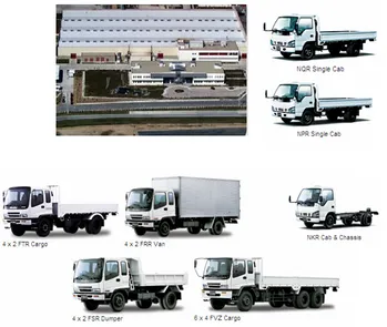
4.3 Isuzu’s Truck product portfolio 67
4.4 General Truck assembly processes 69
4.5 PMI’s Truck flow processes 71
4.6 N-Series Body shop operations 72
4.7 N-Series Body shop manufacturing resources layout 76
5.1 Primary data classification 84
5.2 Current system facilities layout and dimension 85
5.3 Standard time calculation 87
5.5 Example of Standard time calculation 89 5.6 Body Welding and Metal Finish Processes Layout 90
5.7 Transfer time data 91
5.8 Output standard and WIP data 91
5.9 Data quantitative sufficiency test 93
5.10 Example of Workstation’s Standard Time control chart 94 5.11 Example of Statfit’s Auto generated Histogram of the data
Fitted into assigned Probability Distribution
96
6.1 Product assembly process diagram 98
6.2 ARENA Simulation package welcome windows 99
6.3 Main menu description 100
6.4 Simulation Window descriptions 101
6.5 System Performance Indicator Window view 102 6.6 Unanimated real system simulation model 104
6.7 ARENA’s instant model checker 107
6.8 Initial System Simulation Run Characterization 108 6.9 Transient and Steady-State phase identification 109 6.10 Batch Mean Interval Estimation for simulation length
sufficiency test
111
7.1 Daily Output Standard and number of input simulation
result 115
7.2 Finish Product Cycle Time Initial Model Simulation result 116 7.3 Number of Work-in-process (WIP) in Buffer area 117
7.4 Initial Model Workstation Utility 119
8.1 Line balancing approach applied in First improvement
scenario 126
8.2 Proposed Facility Layout for First Improvement Scenario 128 8.3 Parallel operations for second improvement scenario 129 8.4 Proposed Facility Layout for second improvement
scenario 130
8.5 Separated automatic material handling system and process
standardization for third improvement scenario 131 8.6 Proposed Facility Layout for third Improvement Scenario 133 8.7 Full integrated standardized processes with one
non-accumulating automated material handling system
134
8.8 Proposed Facility Layout for fourth improvement scenario 135 9.1 First Manufacturing Re-engineering scenario’s Interfaces 138 9.2 Second Manufacturing Re-engineering scenario’s
Interfaces
138
9.3 Third Manufacturing Re-engineering scenario’s Interfaces 139 9.4 Fourth Manufacturing Re-engineering scenario’s
Interfaces
139
9.5 Animated simulation view for the first Re-engineering scenario
143
9.6 Animated simulation view for the second Re-engineering scenario
143
9.7 Animated simulation view for the third Re-engineering scenario
144
9.8 Animated simulation view for the fourth Re-engineering
scenario 144
10.1 Comparison of output standard for each scenario and
initial model 149
10.2 Comparison of cycle time for each scenario and initial model
151
10.3 Comparison of line efficiency (average resource utility) for each scenario and initial model
10.4 System improvement significance determination using Bonferroni paired-t confidence interval method for output standard variable
154
10.5 System improvement significance determination using Bonferroni paired-t confidence interval method for product cycle time variable
LIST OF APPENDICES
APPENDIX TITLE PAGE
A Thesis Organization 172
B Project’s schedule / Gantt Chart 174
C Isuzu N-Series truck picture and dimension 183 D PT. Pantja Motor organizational chart 184 E PT. Pantja Motor product profile website 185
F Production flow process 186
G Worker layout of N-Series production line 187
H Bill of Material N-Series body 188
I Example of production achievement sheet 192
J Kanban system 193
K Quality control process for N-series body shop 195 L Initial system facility layout and dimension 196 M Standard time data collection result and control chart 197
N Goodness of Fit test summary 224
O Product assembly process diagram 229
P Initial model interface 232
Q Initial model development module and source code 234
R Initial model simulation result 245
S Manufacturing Re-engineering scenario : Facility
layout and dimension 251
T Manufacturing Re-engineering scenario : Interface
U Manufacturing Re-engineering scenario: Source module used
261
V Manufacturing Re-engineering scenario: Simulation
LIST OF ABBREVIATION
BIQ Built-in-quality
BOM Bill of Material
CKD Completely Knock Down
CT Cycle Time
FSKSM Fakulti Sains Komputer dan Sistem Maklumat
FV Face Validity
GOF Goodness-of-Fit
JAD Joint Application Design
LT Load Time
MPV Multi Purpose Vehicle
NT Normal time
PF Performance Rating
PMI PT. Pantja Motor Indonesia PPI Persatuan Pelajar Indonesia
PT Process Time
ST Set-up Time
STT Standard Time
SUV Sport Utility Vehicle UIN Universitas Islam Negeri
UT Un-load Time
UTM Universiti Teknologi Malaysia WBS Work’s Breakdown Structure
WIP Work-in-process
PROJECT OVERVIEW
1.1 Introduction
Along with the rapid growth of technology in last four decades, industrial / manufacturing enterprises confronted in the situation that improvement of the manufacturing performance is the matter which very insist to be certainly achieved. At the other hand, experimental design in existing system will give negative impact for the enterprise. This matter make many companies, finally choose not changed anything to their manufacturing system rather than take a high risk of trial and error processes in experimental design.
Simulation, as a contemporary computer/Information Technology (IT) based technology was raise to minimize that particular risk as mentioned above. In advance to develop a valid simulation model, company can conduct experimental design to get the improvement design of their manufacturing system without disturbing the working system. Computer Simulation model accommodates implementation of various Manufacturing Process Re-engineering Designs into computer based model and simulate it as well as justifying the performances.
Manufacturing and material handling systems provide one of the most important applications of simulation. Simulation has been used successfully as an aid in the design of new production and manufacturing facilities, warehouses, and distribution centers as well as in automotive industries. It has also been used to evaluate suggested improvements to existing systems (Banks et al., 2001). Engineers and analysts using simulation have found it valuable for evaluating the impact of capital investments in equipment and physical facility, and of proposed changes to material handling and layout. They have also found it useful to evaluate staffing and operating rules, and proposed rules and algorithms to be incorporated into warehouse management control software and production control systems. Managers have found simulation useful in providing a "test drive" before making capital investments, without disrupting the existing system with untried changes.
At the other side, as one of the most important sector in manufacturing filed, automotive industries also have been applying Simulation for decision support approach for more than 20 years since the rapid improvement of computer technologies. Many automotive expertises believe that simulation still will be the important decision support approach in Automotive Industries.
1.2 Automotive Industry Environmental Background
Figure 1.1 General step of cars assembly line
An automotive company will typically sequence cars based on several objectives, most dealing with line balancing and material management. In the first and last stages (the body shop and the trim and chassis shop), different cars might require the installation of different components. Such imbalance of the workload at the automotive assembly line can be due to:
1. Different options of the same car model (e.g. one car might have an automatic transmission and sunroof, while another car might have a manual transmission, but no sunroof),
2. Different types of the same model (e.g. sedan vs. wagon), or 3. Different models assembled in the same line.
This project will cover how simulation can be applied into Manufacturing Process Reengineering Design in Automotive industries sub system (which is will explained more detail in the following section) in order to improve their performances using certain manufacturing performance improvement approaches. Manufacturing Process Reengineering will be conducted using simulation based experimental design. Each design will represent the solution alternative that proposed based on particular manufacturing improvement technique.
Later on, as realized, material handling is one of the most important factors regarding to Manufacturing Performance Improvement. Optimal material handling system must drive the manufacturing flow become lean and balance. There are several techniques to increase the material handling performance, whereby one of them is determining the accurate and appropriate facilities layout that can accommodate the criteria of optimum material handling operation.
The other method that will be applied in this project to improve the manufacturing performances is automating the processes. As Groover (2001) stated that Automated Manufacturing had become a popular approach to improve the performances of manufacturing system, especially for the system that produce large number of product with high level of similarities. The common characteristic in automated manufacturing is that the system consists of automated components, such as industrial robot, automated guided vehicles, sensors, and controllers.
1.3 Background of Problem
Figure 1.2 Isuzu Indonesia’s N-series assembly plant and commercial truck model
PMI’s grand total production capacity of whole type is 15000 units per year, whereby the N-Series production is limited only about 6900 unit annually. Since the significant raise of product demand in the past 3 years, so the PMI is facing the problem in improving their production capacity, especially of N-series truck model which is most demanding product.
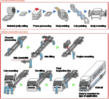
Figure 1.3 Isuzu N-Series Truck General Assembly Process
1.4 Statement of the Problem
Based on the preliminary study and information gathering process through documentary analysis, this project will try to overcome the problems related to the real system. The basic problem of the current manufacturing system is that the production capacity does not meet the future business environment, so the current manufacturing system has to be improved significantly. This general problem also drives several major questions that have to be answered appropriately in order to solve the problem:
1. Does the current manufacturing system is the optimal configuration in terms related to manufacturing system performance?
2. What manufacturing designs may possible significantly improve the current manufacturing / industrial system?
3. How to conduct experimental design to develop scenarios for Manufacturing Performances Improvement without disturbing the real working system?
4. How far the new design can improve the manufacturing performance?
1.5 Project Objective
Based on the case study on PMI’s Body Shop N-series Assembly Line, the project will cover several objectives:
1. To analyze the current Manufacturing or Industrial Performance
2. To study what are the possible manufacturing improvement design which is able to significantly increase its manufacturing performances.
3. To develop/design several improvement alternatives design using Valid Computer Simulation model.
5. To identify the significances of improvement that achieved by implementing those three approach using computer based simulation based.
6. To implement the most valuable manufacturing re-engineering design in the computer simulation model instead of disturbing the real system.
1.6 Project Scope
In case of project coverage area, the following assumption, environmental boundaries, and constraint can be mentioned in determining the project scope:
1. Primary data is collected straightly to the Manufacturing Real system by observation, interviews, sampling methods and time study.
2. Data types that used in this project are the manufacturing variables such as: process time, transfer time, set-up time, standard output, cycle time, number of work-in-process, working time, and other common manufacturing variables.
3. Secondary data are used in case of unavailability of the primary data. 4. Case study is taken from the Job Shop Manufacturing line / Intermittent
Process Industries in Body shop and metal finish of Isuzu N-series Truck assembly line of PT. Pantja Motor, Tbk Indonesia (PMI).
5. Simulation modeling formally will follow Discrete Event Simulation methodology.
6. Simulation model is developed using a Process Oriented Simulation Software which is ARENA version 7.1.
7. Statfit and Microsoft Excel software package will be used for statistical analysis.
8. This project recommendations are only based on manufacturing variable aspect and assume that the real system have no constraint about anything outside the technical manufacturing aspect (e.g financial limitation, land, workforce, and technology).
10.Complexity of the real system, time, and the capability in making computer simulation model will be the most consideration in determining how deep alternative designs will be proposed.
1.7. Importance of Project
Based on what have been illustrated before, generally this project will recommend several scenarios of manufacturing improvement design for the certain case studies. The improvement significances will be determined by a valid simulation model so that the users or clients will more easily justifying the right policies. More detail, the project potential benefits to the organization can be defined as follows:
1. Users can use the initial valid simulation model for analyzing their manufacturing process at particular stages more conveniently and efficient than studying directly through the real system.
2. With the computer based simulation model, the company may conduct the experimental design iteratively to find their best solution regarding to improve manufacturing system accurately and safely rather than do the experiment in their working system whereby definitely disrupting and deal with high risk probability.
3. Simulation model can be capable enough to predict what are the consequences and following effects that might be raised from a certain strategies implementation.
4. The result of the project will contribute the management a valuable input and consideration for supporting their decision making processes.
1.8. Organization of Thesis
This Master Project report is consist of eleven Chapters which are describe about seventeen Project’s steps as attached in Appendix A.
1.9. Chapter Summary
Simulation is one of tools that have been used widely in several manufacturing area and organizations. Using a valid simulation model may possible give several benefit and advantages in creating the better manufacturing design in order to improve the performances. This project is concerning in implementing a computer based simulation model to design scenarios for performances improvement.
Manufacturing process reengineering design will be based on three approaches and principles: minimizing imbalance workloads in assembly line, improving material handling capabilities through facilities re-layout, and automating the manufacturing processes. Meanwhile, Body Shop and Metal Finish department of PMI’s Isuzu N-Series assembly plant will be the base of the project’s case study.
Altinkilinc, M. (2004). Simulation-based layout planning of a production plant. Virginia. Old Dominion University. Proceeding of 2004 Winter Simulation
Conference. 1079-1084.
Banks, J., Carson, J.S., Nelson, B.R., Nicol, D.M. (2001). Discrete Event System
Simulation. New Jersey, Prentice Hall.
Barton, R. R. (2004). Designing simulation experiment. Proceeding of 2004 Winter
Simulation Conference. Pennsylvania. 73-79.
Berger, M. A, Johnston, Vincent F, Hua, Jinyi. (1999). Development of simulation model for an army chemical munitions disposal facility. Proceeding of 1999
Winter Simulation Conference. 790-197.
Carson, J. S. (2004).Introduction to Modeling and Simulation.Proceeding of 2004
Winter Simulation Conference. 9-16.
Cheng, F. S. (2000). A methodology for developing robotic workcell simulation models. Proceeding of 2000 Winter Simulation Conference. 1265-1271.
Cochran, D. S., Duda, J.W., Linck, J. (1998). Simulation and production planning for
manufacturing cells. Massachusetts Institute of Technology: Master Thesis.
Dahl, T. A. and Jacob, B. F. (2000). Confident decision making and improved throughput for cereal manufacturing with simulation. Proceeding of 2000
Winter Simulation. 1329-1332.
Dennis, A., Wixom, B. H., and Tegarden, D. (2002). Systems analysis and design :
an object-oriented approach with UML. New York. John Wiley & Sons.
Farahmand, K. (2000). Using simulation to support implementation of flexible manufacturing cell. Texas A & M University: Ph.D Dissertation.
Fujii, S., Morita, H., and Tanaka, T. (2000). A basic study of autonomous characterization of square array machining cells for agile manufacturing.
Grabau, M. R., Maurer, R. E., and Ott, D. P. (1997).Using a simulation to generate the data to balance an assembly line. Proceeding of 1997 Winter Simulation
Conference. 733-738.
Groover, M. P. (2001). Automation, Production Systems, and Computer-Integrated
Manufacturing. New Jersey. Prentice Hall International, Inc.
Hee-Han, Y., Zou, Chen., Bras, Bret., McGinnis, Leon., Carmichael, Carol. (2002). Paint Line Color Reduction in Automobile Assembly Through Simulation.
Proceeding of 2002 Winter Simulation Conference. 1204-1209.
Ingalls, R. (2002). Introduction to Simulation. Proceeding of 2002 Winter Simulation
Conference. Oklahoma. 7-16.
Kelton, D.W., Sadowski, R. P., and Sturrock, D. T. (2004). Simulation with Arena. Boston: McGraw-hill Higher Education.
Kosfeld, M. A. (1999). Warehouse design through dynamic simulation. Arizona. Intel Corporation. Proceeding of 1999 Winter Simulation Conference. 1049-1053.
Kosfeld, M. A. and Quinn, T. D. (1999). Use of dynamic simulation to analyze storage and retrieval strategies. Arizona. Intel Corporation. Proceeding of 1999
Winter Simulation Conference. 736-741.
Law, A. M. (2003). How to conduct a successful simulation study. Winter
Simulation Conference 2003. Tucson Arizona. 66-70.
Law, A. M. and Kelton, D. W. (2000). Simulation Modeling and Analysis. Boston: McGraw-Hill Higher Education.
Lu, R. F. and Sundaran, S. (2002). Manufacturing process modeling of Boeing 747 moving line concept. Seattle. The Boeing Company. Proceeding of 2002
Winter Simulation Conference. 1041-1045.
Miller, S. and Pegden, D. (2000). Introduction to Manufacturing Simulation. Rockwell Software, Inc.
Mills, M. C. (1988). Using group technology , simulation, and analytical modeling in the design of a cellular manufacturing facility. California. McDonnell Douglas Helicopter Company. Proceeding of 1986 Winter Simulation Conference. 657-659.
Mungwattana, A. (2000). Design of cellular manufacturing system for dynamic and uncertain production requirements with presence of routing flexibility.
Nikoukaran, J. (1999). Software selection for simulation in manufacturing : a review. In Simulation Practice and Theory. Proceeding of 1999 Winter Simulation Conference. 1-14.
Park, Y. H., Matson, J. E., and Miller, D. M. (1998). Simulation and analysis of the Mercedez-Benz Production Facility. Proceeding of 1998 Winter Simulation
Conference. 132-137.
Patel, V., Ashby, J., and Ma, J. (2002). Discrete event simulation in automotive final process. Michigan. General Motors. Proceeding of 2002 Winter Simulation
Conference. 1030-1034.
Piekert, A., Thoma, J, and Brown, S. (1998). A rapid modeling technique for measurable improvements in factory performance. Munich. Siemens AG Germany. Proceeding of 1998 Winter Simulation Conference. 1011-1014. Roser, C., Nakano, M., and Tanaka, M. (2002). Throughput analysis using a single
simulation. Nagakute, Aichi. Toyota Central Resercah and Development Department. Proceeding of 2002 Winter Simulation Conference. 1087-1094. Saand, S. M., Parera, T, and Wickramarachci, R. (2003). Simulation of distributed
manufacturing enterprises : a new approach. Sheffield. Sheffield Hallam University. Proceeding of 2003 Winter Simulation Conference. 1167-1173. Shady, R., Spike, G., and Armstrong, B. (1997). Simulation of new product workcell.
Proceeding of 1997 Winter Simulation Conference. 739-743.
Shannon, R. E. (1975). Systems Simulation – The Art and Science. Prentice-Hall. Silva, L., Ramos, L. A., and Vilarinho, P. M. (2000). Using simulation for
manufacturing process reengineering – a practical study. Aveiro Portugal. Campo Universitario de Santiago Portugal. Proceeding of 2000 Winter
Simulation Conference. 1322-1328.
Springfield, K. G., Hall, J. D., and Bell, G. W. (1999). Analysis of electronic assembly operation : longbow hellfire missile power supply. Proceeding of
1999 Winter Simulation Conference. 689-693.
Stevenson, William J. (2005). Operations Management. McGraw-Hill International Tan, G., Zhau, N., and Taylor, S.J.E. (2003). Automobile manufacturing supply
chain simulation in the grid environment. Proceeding of 2003 Winter
Simulation Conference. 1149-1157.
Ulgen, O., Gunal, A., Grajo, E., and Shore, J. (1994). The Role of Simulation in Design and Operation of Body and Paint Shops in Vehicle Assembly Plants.
Proceedings of The European Simulation Symposium, Society for Computer
Simulation International, 1994.
Walpole, R. E. and Myers, R. H. (1997) Probability and statistic for engineers and
scientists. New York: Macmillan Publisher.
William, E. J. and Sadakane, S. (1997). Simulation of a paint shop power and free line. Michigan. Ford Motor Company. Proceeding of 1997 Winter Simulation
Conference. 727-732.
Williams, C. L. and Chompuming, P. (2002). A simulation study of robotic welding system with parallel and serial processes in the metal fabrication industry. Memphis. University of Memphis. Proceeding of 2002 Winter Simulation
Conference. 1018-1025.
Williams, E. J. and Orlando, D. E. (1998). Simulation applied to final engine drop assembly. Michigan. Ford Motor Company. Proceeding of 1988 Winter