ADOPT: Practical Add-On MIMO Receiver for
Concurrent Transmissions
Sungro Yoon,
†
Bang Chul Jung, Kyunghan Lee and Injong Rhee
North Carolina State University,
†
Gyeongsang National University
{
syoon4, klee8, rhee
}
@ncsu.edu,
†
[email protected]
Abstract—Recent MIMO-based techniques allow concurrent transmissions of packets. With signals received from multiple antennas, a receiver can extract concurrently transmitted packets solving linear equations. While the receiver requires essential physical layer parameters for such MIMO decoding, existing signal processing techniques are not capable of obtaining those parameters from interfered preambles. Thus recent proposals enforce communicating senders and receivers go through non-overlapping training period per each packet transmission. For example, senders precisely schedule transmissions such that preambles of the concurrent packets do not overlap. But this coordination process is not trivial and significantly reduces the efficiency of concurrent transmissions. We present ADOPT, a practical add-on MIMO receiver for decoding concurrent transmissions in the absence of coordination. Using the unique combination of novel signal processing technique, calledFDCM, with existing linear adaptive filters, ADOPT successfully performs packet decodings in uncoordinated transmissions. Using FDCM, ADOPT can obtain the essential physical layer parameters - carrier frequency offset and the start of frames, from overlapped or interfered preambles. The information is then fed into the linear adaptive filter, that in turn extracts each packet successively. As a result, ADOPT builds as a complete black box decoder and increases the link efficiency. We implement ADOPT with 8 USRP2s and test in two of the most common CSMA networks, ZigBee and WiFi. Combined with an aggressive channel access, our extensive experimental evaluations show that the throughput gain becomes up to 231% in WiFi and 319% in ZigBee.
Index Terms—MIMO, Multipacket Reception, Receive Beamforming
✦
1
INTRODUCTION
The proliferation of wireless devices caused the public wireless bands, such as ISM (industrial, scientific and medical), heavily saturated. In such a saturated wireless band, when two or more packets are transmitted simultaneously, which frequently happens because of high contention or hidden terminals, the packets become corrupt and cannot be decoded at receivers. Measurement studies [1], [2] over corporate networks show that about 10% of wireless links can suffer more than 70% throughput loss due to collisions from concurrent packet transmissions.
Recently there have been significant advances in the MIMO-based multi-user communication (MUC) [3], [4], [5]. Even though packets are concurrently transmitted and thus interfere with each other, a receiver can decode the packets by solving linear equations with signal inputs from multiple antennas. Naturally, The link capacity becomes larger with more number of antennas.
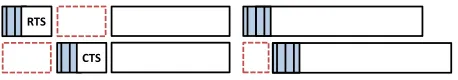
But those techniques have limitations. Essential parameters required for MIMO decoding, such asstarts of frames,carrier frequency offset (CFO) and channel state information (CSI), have been only collected via the non-overlapping, exclusive exchange of known symbol sequences, e.g., packet preambles. The reason is that existing signal processing techniques are mostly designed only for single transmission system and do not consider the cases where the packet preambles are interfered by concurrent transmissions. If a packet preamble is interfered, as Figure 1 (a) shows, a receiver could not
(a) Overlapped preambles in uncoordinated transmissions
RTS
CTS
(b) Non-overlapped preambles in coordinated transmissions
Fig. 1. Shaded regions represent packet preambles. (a) When preambles are partially or fully overlapped, current MUC techniques cannot obtain physical layer parameters. (b) MUC techniques arrange transmissions in such ways that the preambles do not overlap. The region in dotted line is where channel is under-utilized.
preambles are usually transmitted at the lowest link rate and so the relative time portion is quite high [5]. Consequently the channel is under-utilized well below the capacity region of the channel, defined by the degree of freedom (DoF).
Our goal is to design and build a MIMO receiver that enables decoding of uncoordinated packets transmitted concur-rently. To this end, the main challenges lie in how a receiver should (1) extract the essential physical layer parameters and then (2) effectively decode packets, while the packet preambles are overlapped and thus interfered. The difficulty is that the physical layer parameters are tightly coupled. For instances, conventional decoding techniques do not allow a receiver detect CFO using interfered preambles. With the CFO unknown, it is not possible to detect the start of frames and thus to decode the packets. Therefore, our challenges involve simultaneous acquisition of multiple unknown physical layer parameters such as start of frames, CFO and CSI (channel state information) together from interfered preambles.
As an answer, we present a practical MIMO receiver for concurrent transmissions. We call our approach ADOPT, Add-on Decoder for Overlapping Preamble TransmissiAdd-ons. ADOPT detects the CFO and the start of frames simultaneously using a novel signal processing technique called frequency domain correlation and matching (FDCM), which substantially re-duces complexity pertaining to detection of CFO and start of frames by comparing received signals and the known preamble in the frequency domain. Then ADOPT decodes each packet utilizing a linear adaptive filter. The technique, which we call
interference suppression and cancellation, regards overlapping packets as unknown interferences and extracts the packets one by one.
The unique features of ADOPT can be summarized as fol-low. First, ADOPT increases channel utilization. The channel time is saved since now the transmissions of packet pream-bles can be fully overlapped. Second, ADOPT can operate independently from channel access schemes, not requiring supports from upper layer protocols. Thus ADOPT is not exclusive with existing MUC protocols and can work with any of them. In other words, ADOPT builds a complete black box decoder. Just replacing the receiver can improve the network throughput.
We implement ADOPT using 8 USRP2s, well known software defined radio platforms, and evaluate performance in WiFi and ZigBee networks. Our extensive experimental results show that ADOPT can be easily combined with the existing standards. When ADOPT is used with a MAC proto-col allowing aggressive packet transmissions, the throughput increases up to 319% and 231% compared to native 802.11b and 802.15.4 protocols, respectively.
2
MOTIVATION AND
BACKGROUND
In order to perform MIMO decoding, a receiver needs to know channel state information (CSI), starts of packets and carrier frequency offset (CFO). However most existing signal processing techniques, commonly occupied in MIMO-based MUC techniques, are originally designed for a single trans-mission system (e.g., single user MIMO). The challenges can be summarized as follow.
• Acquisition of CSI requires both CFO and start of frames.
• Acquisition of either the CFO or the start of frame requires information of each other.
• When the packet preamble is interfered, both the CFO and the start of frame are unknown.
So MUC proposals require clean (i.e., non-overlapping) preambles to extract physical layer information for MIMO decoding. Enforcing such non-overlapping preamble transmis-sions degrades the channel utilization as coordination overhead is incurred among senders and receivers.
In this work, we aim to propose a MIMO receiver system that is fully capable of decoding packets without coordination. The system thus requires the acquisition of those parameters from interfered preambles. In the following, we entail about each parameter and discuss corresponding challenges more in detail.
Channel state information: Suppose there are two trans-mitters, each equipped with one antenna, and a receiver with two antennas. When both transmitters transmit, their signals are summed up linearly over the air and the following linear equations are derived:
y1 = h11x1+h21x2+w1 (1)
y2 = h12x1+h22x2+w2, (2)
where yj are outputs from receiving antennas, hij is the channel coefficient (i.e. CSI) between a transmitter i and a receiver antenna j, andwj is the noise. Given a receiver has CSI, two linear equations have two unknowns (x1 andx2), so
we can solve them.
The CSI can be obtained via the channel training process, in which a receiver compares an incoming packet preambles with its knowledge. Typically either linear correlator [6] or minimum mean squared error (MMSE) [5] criteria is used.
The conventional channel training method uses an MMSE-based technique where channel coefficients from all trans-mitters are explicitly estimated. To estimate the coefficients, MMSE-based channel estimation uses a short training se-quence (around 5 symbols). Here it is required that the training sequence is sent in a clear channel without any interference. The challenge is that in uncoordinated concurrent transmis-sions, the entirety of the preamble may be overlapped with interfering signals. Unless the interfering signals are explicitly modeled and cancelled from the received signals, we cannot use MMSE. Therefore, most of the existing MUC techniques use interference cancellation to remove the interferences. But the problem is that in many situations, the interfering signal cannot be exactly modeled. And it is the reason why MUC protocols coordinate the senders to avoid preamble overlaps.
Start of frames: When there is only a single transmission, a receiver can immediately know the start of that frame by observing an energy level. In case multiple packets arrive at a receiver concurrently, the starting positions should be accurately detected for measuring CSI as a next step. It is because, the receiver needs to know when to start the training process between incoming signals and its known sequences.
observes similarity between incoming signals and a priori known symbol sequence. For a given known sequence of samples, x = x0, x1, . . . , xp and an input timed series of symbols at time t, yt, yt+1, . . ., correlation multiplies each
component independently and sums them up as follows:
C =
p
X
i=0
xiy′j+i. (3)
Then it shifts the alignment by one sample of the input and obtains another correlation value. The start of a frame is estimated to be the sample index of the first sample that produces a spike, the maximum correlation value (e.g., [6], [5]). As we will see, the correlation does not work well with carrier frequency offsets. Bottom of Figure 5 shows the preamble correlation result when multiple packets overlap. The correlation is performed without CFO compensation. As shown, the correlation does not yield a distinguishable peak if without proper CFO compensation.
There are other techniques for collision detection. SoftPHY [7] detects the increase of sample dispersion in the constella-tion map when a packet is overlapped with another. This tech-nique is effective in detecting the presence of errors incurred by packet collision, but cannot be used to find the collision points of more than two overlapped packets since dispersions from two packet collision are hard to be distinguished from three or more packet collision. It is proposed [8], [9] to use the increase in the amplitude variance within received signals when packet collision occurs. This technique is effective only if signal strength is very strong; otherwise, the amplitude variance is easily influenced by the background noise.
Carrier frequency offset: CFO is caused by (1) natural differences in the carrier frequencies, generated by respective oscillators of a sender and a receiver or (2) doppler shifts due to movements [10], [11]. IEEE 802.11n [12] defines the allow-able CFO range of ±60KHz at 2.4GHz, ±100KHz at 5GHz and 802.15.4 [13] allows ±96KHz at 2.4GHz channel. CFO incurs phase rotations in the received samples. For instance, a sinusoidal wave with a frequencyfT x sampled at a periodic interval 1/fT x will produce the same value. But with CFO, the values sampled at every 1/fRx = 1/(fT x + ∆f), even starting from the exact same phase, will have displacements and eventually produce different values. In order to decode a packet, a receiver should accurately model the CFO.
Correlation is not effective in the presence of CFO. A correlation value at a start of a frame will be given as:
C(t) = h
p−1
X
k=0
|xk|2e2πik∆f T, (4)
where p is the preamble length, xk is the k-th symbol in a preamble, h is the channel coefficient vector, T is the symbol duration and ∆f is the CFO. With the exponential terme2πjk∆f T
, CFO produces a phase rotation of each symbol
xk which cancels each other during the summing process. Finding the correlation peak over the time domain, therefore, must entail cancelling out the exponential term, which is not possible without knowing ∆f.
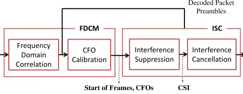
Frequency Domain Correlation
Start of Frames, CFOs Interference Suppression
Interference Cancellation CFO
Calibration
FDCM ISC
Decoded Packet Preambles
CSI
Fig. 2. Block diagram of the ADOPT decoder.
CFO can be obtained via measuring the amount of phase ro-tation per symbol within a known symbol sequence. However in case a receiver receives concurrently transmitted packets, the process is not trivial. While the receiver has to determine the starting position of a packet to compute CFO, the correla-tion technique does not work without compensating for CFO. It has been suggested that CFO is precomputed for all the possible senders when a packet from each is sent alone in a clear channel [6], [3], [14]. The problem is that CFO can be incurred by doppler shifts and in this case precomputed values will be inaccurate. But more fundamentally, when several packets overlap in their preambles, there is no way that the receiver can identify the transmitter of each received packet and thus which CFOs to apply accordingly. A brute force technique is to try all the possible CFOs, but it is too time-consuming and prohibitive in terms of computational power. So this approach might be applicable to a small, static network. Another approach lets all the senders tune their carrier frequency to the respective receiver when they transmit [15], [4], [16], [17]. But the synchronization overhead could be non-negligible. Also in case there could be errors in the synchronization, the receiver still needs the ability to compensate for CFOs.
3
PROPOSED
SYSTEM: ADOPT
ADOPT decodes packets from the overlapped signals using the information obtained from overlapped preambles. The ADOPT architecture mainly consists of two components: frequency-domain correlation and matching (FDCM), and interference suppression and cancellation. FDCM is a novel technique that performs 2-dimensional search to find both (1) CFO and (2) starts of packets from incoming overlapped preambles, with significantly low computational overhead. With these param-eters, we combine interference suppression and cancellation techniques to decode the concurrently transmitted packets. ADOPT is deliberately designed to serve as a black box decoder, that operates independently of upper layer protocols. Figure 2 shows our system design.
3.1 FDCM
FDCM utilizes frequency spectrum of a packet preamble and that of the incoming signals. We have timed input samples
y = y0, y1, y2, . . . and samples from the preamble x =
x0, x1, . . . , xp−1. We takepsamples from both and apply FFT
between frequency spectrum of the two sample sequences. This is a two dimensional search. We find a frequency and time pair(δ, τ), where δis the frequency value that produces a correlation spike and τ is the time instance when δ has been found, respectively. This process is repeated until the end of the received samples by shifting one sample of the input signals at a time to get another psamples.
The intuition behind FDCM is simple: an exponential change in the time domain becomes linear in the frequency domain. This is also known asshift theorem. So the exponen-tial term e2πik∆f T in Eq. (4) becomes a constant frequency shift in the frequency domain. If the frequency spectrum of the preamble sequence has a low autocorrelation in the frequency domain, then the unknown frequency offset ∆f
can be estimated by finding the peak in frequency domain correlation. The intuition is analytically explained by the following.
When DFT (discrete Fourier transform) is applied to a fixed number of received signal samples of a packet, the frequency spectrum at each frequency fk is represented as
Sr(fk) = H(fk)·Sp(fk−∆f), (5)
where Sr(fk), Sp(fk), H(fk) and∆f denote the frequency component of the received signals at frequencyfk, the original frequency of the preamble (i.e., DFT results of the preamble), the k-th frequency response of the wireless channel and the CFO, respectively. Note that fk is a discrete value such that
fk = 2kRN Hz, where k ∈ {0, . . . , N −1}, N is the number of samples used for DFT (i.e., the number of frequency bins) andR is the sampling rate.
By taking correlations between the DFT results of received signal and the known preamble, it is possible to reliably detect both the start of frames and CFOs. The correlation is computed for each δ∈ {f0, . . . , fN−1} as below.
C(δ) =
NX−1
k=0
Sr(fk+δ)·Sp∗(fk) (6)
= NX−1
k=0
H(fk)Sp(fk+δ−∆f)·S∗p(fk),
where S∗
p(fk)is the complex conjugate of thek-th frequency component of the preamble sequence.
Now, suppose a receiver has received packets Pa and
Pb simultaneously, whose frequency spectrum are frequency spectrum Sa and Sb, respectively. Then Sr(fk) is the linear sum of each packet’s frequency components:
Sr(fk) = Ha(fk)·Sp(fk−∆fa) (7)
+ Hb(fk)·Sb(fk−∆fb) +W(fk)
where Ha(fk) and Hb(fk) indicate the k-th frequency re-sponses, ∆fa and∆fb are the CFOs of packets Pa and Pb, respectively.W(fk)represents thek-th frequency response of the background noise at the receiver. We take correlation in frequency domain and from Eq. (6) and Eq. (7), the result at
−1 −0.5 0 0.5 1
x 104 0
2 4 6 8x 10
7
Correlation
Frequency (kHz)
Fig. 3. Autocorrelation of ZigBee preamble in frequency domain.
−4000 −200 0 200 400
1 2 3 4x 10
7
Correlation
Frequency (KHz)
Fig. 4. Two ZigBee packets are transmitted at the same time slot. Each packet has CFO of -55.5KHz and 21KHz, respectively. ADOPT reliably detects perfectly aligned packets and their CFOs.
δ= ∆fa is computed as:
C(∆fa) =
NX−1
k=0
Sr(fk+ ∆fa)·Sp∗(fk) (8)
= NX−1
k=0
[Ha(fk)Sp(fk)·Sp∗(fk)
+ Hb(fk)Sp(fk+ ∆fa−∆fb)·Sb∗(fk) + W(fk+ ∆fa))·S∗p(fk)].
If the preamble has a low autocorrelation and a cross-correlation in the frequency domain, the second and third terms will cancel out and Eq. (8) is simplified as:
C(∆fa) ≃
NX−1
k=0
Ha(fk)· |Sp(fk)|2, (9)
which produces a spike at δ = ∆fa. We argue that our assumption of low autocorrelation and low cross-correlation of preambles in the frequency domain is valid in reality. We have found experimentally that the packet preambles of CSMA standards such as ZigBee and WiFi satisfy the same property in the frequency domain. Figure 3 shows the autocorrelation of the ZigBee preamble in the frequency domain.
Co
rr
ela
tion
Fig. 5. Top: FDCM results of 8 concurrently transmitted ZigBee packets. 8 peaks identify both CFOs (y-axis) and starting positions (x-axis) of 8 packets. Bottom: correlation of the same signal in time domain. No distinct peaks are visible.
spikes at the frequency index of ∆fa and∆fb. As Figure 4 shows, FDCM produces multiple spikes at the start of each packet when the CFOs of the senders are different from each other. This is very likely in reality. After detecting multiple packets and their CFOs, the receiver can start to decode each packet. Our technique of decoding the overlapped packets is explained in Sec. 3.2.
Figure 5 compares the outpus from the proposed FDCM and the conventional time domain correlation. Our test is performed on the received signal dump consisting of eight collided ZigBee packets. In the conventional time domain correlation, the CFOs of collided packets have not been compensated. As Eq. (4) describes, the time domain corre-lation value is substantially distorted and the result does not easily identify any start of packet. On the other hand, FDCM clearly identifies starts of packets as well as CFOs by the
(time, f requency) coordinates of the peaks.
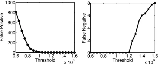
To the best utilization of FDCM, the threshold for detecting the peaks needs to be determined carefully. If the threshold is too low or high, the false positive or negative probability becomes too high. In Section 5, we empirically provide a threshold value which gives very low false negatives while maintaining a reasonable level of false positives.
3.1.1 Complexity Reduction
Despite its efficacy, high complexity of FDCM would make it less practical. For each incoming sample, FDCM computes FFT on N samples and perform correlations. While the FFT takes O(N·logN), the correlation operation compares theN
samples at N different frequencies and thus involvesO(N2)
computation.
Now we propose FFDCM (fast FDCM) that substantially re-duce the complexity and the computational overhead. FFDCM exploits following observation: the frequency spectrum of a packet preamble exhibit high energy only at a few frequency
100 101 102 103
0 2 4 6x 10
7
Number of chosen frequency samples
Correlation value
Fig. 6. The maximum correlation value when the number of chosen frequency samples is varied.
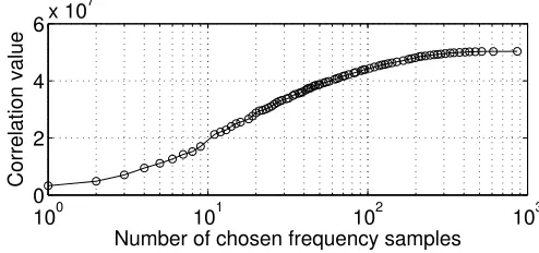
bins. But most of the frequency bins at other frequencies carry energy that almost amounts to zero. This is due to the repetitive nature of symbol patterns in the preamble. For example, ZigBee preamble repeats the same sequence of 32 chips 8 times and WiFi (802.11b) preamble repeats identical 11 chips 192 times. By using only the FFT points with high energy, FFDCM can find the almost the same correlation results while having the significantly reduced computational overhead.
FFDCM computes the correlation in the frequency domain at selected (fi, Sr(fi)) and (fi, Sp(fi)) pairs. fi is chosen such that|Sp(fi)|> thresh. Now Eq 6 rewrites as
C(δ) = XSr(fi+δ)·Sp∗(fi), fi ∈ {f0. . . fk−1}
= XH(fi)Sp(fi+δ−∆f)·Sp∗(fi).
Givenk, the total number of chosen FFT points, FFDCM takes
O(k·N)computations at each incomping signal sample. So the overall complexity is upperbound by FFT, which takes
O(N logN). Figure 6 shows our experimental result from
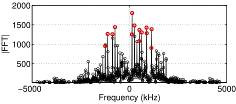
ZigBee testbed, where the the maximum correlation values from FFDCM are shown with the varying number of chosen frequency We see that use of 20 frequency samples still yields around 60% correlation peak compared to the case when all of 1024 samples are used. As an example, in figure 7(a) we take 14 of the most significant FFT points out of total 1024 points. Despite the complexity reduces by 80 folds, figure 7(b) clearly shows that the detection performance is still maintained.
3.1.2 CFO Calibration
The number of samples used for FFT determines the resolution of CFO estimation. However as the length of preamble is fixed and cannot be extended arbitrarily, there always exists a certain range of estimation errors. We call this residual CFO. For example, as for IEEE 802.11b, we have 144×11 = 1584 symbols in the preamble (144 symbols each being spread using 11 chips). If we use 20MHz radio receiver, we can detect CFO with 20M/2/1584 = ±3.16KHz resolution. We can further refine the estimate by increasing the number of frequency bins, for example, using interpolation or oversampling. But it could significantly increase the complexity or the energy consumption in the receiving device.
−5000 0 5000 500
1000 1500 2000
Frequency (kHz)
|FFT|
(a) Frequency spectrum of the ZigBee preamble. Red circles shows total 14 points that have higher amplitudes.
−4000 −200 0 200 400
1 2 3x 10
7
Frequency (kHz)
Correlation
(b) Correlation result of the captured ZigBee signals (SNR = 2dB) and the selected FFT points of ZigBee preamble.
Fig. 7. Using only the significant FFT samples, FFDCM is able to reliably perform correlation in the frequency do-main with substantially reduced computational overhead.
preamble using the coarse CFO estimates and (2) estimate the residual CFO using the decoded preamble. Before attempting to decode data portion of a packet, we apply MIMO decoding only to the preamble and extract the preamble symbols. Since the preamble size is small and the current CFO estimate is obtained using the entirety of that preamble, the coarse CFO is always good enough to decode it. Note that the symbol phase rotation due to the residual CFO error is limited to at most one during that time. With those symbols completely known, the residual CFO can be estimated by measuring the amount of phase rotation between the first and last symbols of the preamble. We extract a preamble using an adaptive filter, which is explained in Sec. 3.2. As the adaptive filter has the linear complexity, it takes O(P)computations whereP is the preamble length.
3.2 Interference Suppression
A typical MIMO receiver requires CSI to solve Eq. (2), for the decoding of concurrent packets. However explicit modeling of CSI is often not feasible in uncoordinated networks where preambles overlap. In order to avoid the explicit estimation of CSI, ADOPT uses a linear adaptive filter. The adaptive filter formsWdirectly from the received signals without explicitly modeling individual CSI [18]. Here W is defined as n×m
Pa
Pb
sa
sb
ea
eb
Oa
Ob> LRLS
Fig. 8. Interference suppression using RLS; RLS can be applied to decodePaandPb.
matrix such that
x = W·y, (10)
wherey is the received symbol vector with lengthmandxis the transmitted symbol vector with lengthn. The main benefit of using the adaptive filter is that it can extract a packet in the presence of unknown interference signals. W converges via an iterative process to produce minimum estimation error, even when the sequence is overlapped with other signals [18]. The adaptive filter has not been actively used for the channel training purposes in the context of concurrent transmissions. It is because of its requirement of a relatively long symbol sequence [19]. However, given that most wireless communi-cation standards (e.g., 802.11 and 802.15.4) have sufficiently long preambles with low autocorrelation, we can make use of adaptive filters for decoding concurrent packets.
Among several different choices (e.g., LMS, Kalman, etc.), we choose recursive least square (RLS) for our implemen-tation and evaluation. RLS has the smallest error in a static environment where the channel state changes relatively slowly (e.g., nodes are stationary)1. RLS uses the following iterative algorithm:
Wi = Wi−1+ (xi−Wi−1yi)yi∗ρi
ρi = λ−1[ρi−1−
λ−1ρ
i−1yiy∗iρi−1 1 +λ−1y∗
iρi−1yi ],
where the initial value of ρi is given as ρ−1 =ǫ−1I with ǫ
being a very small constant.λis a forgetting factor,0≪λ < 1.Wiconverges iteratively with an error feedbackxi−Wi−1yi [20], [18].
3.2.1 Decoding of two packets in overlap
Now consider a scenario where two packets Pa and Pb are overlapped as in Figure 8. We show how packet Pb can be decoded in the presence of Pa. Let LRLS2 be the minimum
preamble length required for training an RLS filter, andOibe the time duration that the preamble of packeti overlaps with the other packet. To simplify the discussion, we assume that starts of packets and CFOs have been already identified via FDCM.
ADOPT always first decodes a packet that has arrived later. The reason is that, in order to remove certain interfering signals from a packet, W should be built upon the preamble
1. We can consider switching to LMS (least meansquares) for a fast time-varying channel, but we leave it as future work.
that is interfered by those signals. In Figure 8, the preamble of Pb fully overlaps with Pa. So RLS can trainW such that it can cancel out the interference of Pa. However if W is trained using the preamble of Pa and if Oa < LRLS, RLS
cannot secure a sufficient number of iterations to obtain the information aboutPb’s interference. Thus decoding of bothPa and Pb will fail. After deciding to decode Pb first, ADOPT adjusts received signals to compensate for the CFO of Pb.
Now denote y as an m-rank vector of received symbol values given that a receiver hasmantennas. Since the number of concurrent transmitters is unknown, we set x to have the same rank as y such that xi = [s1,i, . . . , sm,i]T where sk,i represents the i-th preamble symbol from the k-th transmit-ter. Suppose that Pb is transmitted by a node k. ADOPT treats all the interferences such as Pa as unknown during the decoding process of one packet, Pb. So all the symbols from the other nodes are assumed to be zero. So we have
xi = [0,0, . . . , sk,i,0, . . . ,0]T. Training W over LRLS, we
decodePbfrom the simple operationxˆ=W·y. Note that the later portion of Pb, not overlapped with Pa, can be treated as if Pa is transmitting virtual null signals (denoted by a dotted box in Figure8). This portion does not affect the result of operations. Recall that if a receiver knows about all the coefficients in Eq. (2), it can solve the equation to obtain x2
even when x1 is 0.
This technique is considered as interference suppression
because interfering signals are not explicitly modeled, but instead treated as unknown interferences. RLS filtering can be understood as a receiver side beamforming [21] that ad-justs the antenna gains to suppress the interferences without individually modeling each signal.
AfterPbis successfully decoded, it is possible to cancel out the contribution of Pb from superimposed signals. Of course,
if Oa > LRLS, it is possible to directly apply RLS to decode
Pa. Otherwise ADOPT utilizes the interference cancellation technique [8], [3], [5]. Since Pb is decoded using RLS, it can be subtracted from the mixed signals to expose Pa in a clear channel. As this technique is extensively studied in the literature, we omit the detail.
We considered an example where two packets have been transmitted at different time instances and thus have distinct starting points sa andsb. This is a common colliding pattern for hidden terminals. In this case, RLS could use an identical preamble as training sequences for the two different packets. It is because the preamble has the low autocorrelation property and the packets overlap at different symbol indices.
But what happens if two senders with identical preambles begin transmissions at a same time instance and so the starts of the packets are perfectly aligned? Note that the two packets usually have different CFOs. As ADOPT extracts one packet at a time, say Pb, all the incoming signals are adjusted to compensate for the CFO of Pb. Then as Eq.(4), the preamble of another packet, Pa, will look like a random pattern when seen in the time domain. RLS can decode Pb by considering
Pa as an unknown interference. In an actual network, it is extremely rare that two transmitters have the same CFO and also their packets are received in a completely aligned manner.
p
‰[
s e Decoding Sequence
4
1
2
3
Fig. 9. There is always at least one RLS-decodable packet in any overlapping set. A packet with the latest time interval[p′, p]is always RLS-decodable.
3.2.2 Decoding of three or more packets in overlap
Now we consider cases when more than two packets are over-lapped. Figure 9 shows an examples. We show that interference suppression and cancellation discussed in Section 3.2 can be extended to decode more than two concurrent packets.
We denote the start and end times of a packet Pi to be
si andei, and the time at which its preamble ends to bepi.
So si < pi < ei. We say that two packets Pi and Pj are
directly overlapped if si ≤ sj ≤ ei or vice versa. Pi and
Pj are transitively overlapped if (1) there exists a sequence of packets P1, . . . , Pl such that Px and Px+1 (1 ≤ x < l)
are directly overlapped and (2)Pi andP1, and Pl andPj are directly overlapped respectively. We define anoverlapping set
S to be the set of packets such that any two packets,Pi and
Pj, are directly overlapped or transitively overlapped.
Lemma 3.1: A packetPkin an overlapping setSis decod-able by RLS if there is no directly overlapped packet inSthat starts afterp′
k:=pk−LRLS.
Proof:Here pk is the ending point of the preamble. The lemma can be informally shown as follows. By the definition, all the packets in the overlapping set of S are directly or transitively overlapping withPk. Recall that RLS filtering can train W if the training duration is longer than or equal to
LRLS. As no directly overlapped packet starts afterp′k by the assumption, the RLS filter can be sufficiently trained during a period[p′
k, pk]and successfully decodePk. However, if there is any directly overlapped packet starting afterp′
k, RLS does not have enough training symbols to converge to a good filter that is able to decodePk.
We say that Pk in Lemma 3.1 is RLS-decodable. In any overlapping set, we can prove that there is at least one packet that is RLS-decodable.
Lemma 3.2: In any overlapping set S, there exists at least one RLS-decodable packet.
Proof: We can prove this by contradiction. Suppose that every packet has some directly overlapping packet starting after the time instancep′
k =pk−LRLS. So none of the packets
in S is RLS-decodable. Consider a packet Pl whose ending time el is the last among those in S. By the contradiction hypothesis, there is at least one directly overlapping packet
Pj starting after p′l. Then sincePl finishes last,Pj must end before or at el. Then the length ofPj is less thanPlbecause
Pj starts later thanPland ends beforePl or at the same time with Pl. By the same logic, Pj must have another directly overlapping packet starting afterp′
before or at ej. Again, the length of that packet will be less thanPj. This argument continues to reduce the packet length further, and eventually we will have a packet whose length is less than the length of preamble. This is a contradiction because the length of a packet must be larger than that of preamble.
In general, a packetPk with the latest time interval[p′k, pk] is always RLS-decodable. After the RLS-decodable packets are decoded, we can cancel out their signals from the original signals so that no packets in the residual signals are overlap-ping with the decoded packets. Then we haveS′=S − {Pk}. Lemma 3.2 also applies to S′ and it has at least one RLS-decodable packet. By induction, we can claim that all packets inS can be sequentially decoded. Figure 9 shows examples of overlapping sequences of packets which illustrates the order of RLS-decoding.
3.2.3 Complexity
RLS is a linear filter so it will take O(P)for training where
P is the preamble length. The actual filtering will take O(n) for nsamples in a packet. Interference cancellation also takes
O(n).
4
IMPLEMENTATION AND
SETUP
In this section, we describe our implementation of ADOPT using 8 USRP2s running GNU radio platforms, and the configuration of our test. ADOPT is implemented using 8 USRP2s with GNU radio platform. We test ADOPT in ZigBee (IEEE 802.15.4) and WiFi (IEEE 802.11b). While ADOPT can work with any type of channel access schemes, we choose these two networks to demonstrate the general applicability of ADOPT as they are two of the most common CSMA networks.
4.1 Hardware and Software Setup
An ADOPT receiver consists of eight USRP2, each attached with one RFX2400 daughter board. The system forms an 8 antenna MIMO receiver. Each USRP2 is connected to a PC through a gigabit Ethernet. An USRP2 dumps the incoming digital samples received from its transceiver to the PC. We operate USRP2s at the sampling rate of 25 million samples per second. This signal dump is analyzed offline. Figure 10 (a) shows the ADOPT receiver. Note that we do not necessarily synchronize those USRP2s because it is possible to accurately detect start of each frame in each signal dump using FDCM. To investigate the performance of ADOPT in testbeds, we deployed 18 MICAz nodes each with a CC2420 ZigBee com-pliant transceiver running TinyOS and 40 WiFi nodes running MadWiFi driver over Atheros 802.11b cards. Note that because of its communication overhead with PCs the USRP2 receiver cannot communicate with senders in realtime (e.g., cannot ACK). Instead, clients are associated with a native AP (or sink) which is different from the ADOPT receiver and they directly communicate with that AP. An ADOPT receiver is placed right next to the AP and it passively receives incoming packets. For the simplicity, we do not test multiple AP scenarios, but instead we adjust the carrier sensing thresholds of clients in order to manually create hidden terminals.
The deployment maps of ZigBee and WiFi networks are shown in Figure 10. The received SNR at the AP is between -7dB to 12dB, and 2dB to 35dB for the ZigBee and WiFi testbeds, respectively. ZigBee nodes have CFOs in the range between 55KHz and 40KHz and WiFi nodes have between -40KHz and 25KHz with normal distribution around the center frequency.
4.2 Physical Layer Characteristics
Both ZigBee and WiFi use CSMA/CA for media access control and transmit in the 2.4GHz ISM band. However, they have completely different physical layer characteristics that include physical rate, coding, modulation and preamble length. While CC2420 transmits at a fixed data rate of 250Kbps, IEEE 802.11b can transmit at various data rates ranging from 1Mbps to 11Mbps. We choose 11Mbps for WiFi and disable the rate adaptation.
ZigBee maps every 4 bits into 32 chips of pseudo noise codes. Then every two chips are modulated into one OQPSK symbol by the CC2420 chipset. 11Mbps IEEE 802.11b uses DSSS with CCK of 8 chips per symbol and every two chips are converted into a DQPSK symbol. While DQPSK is a differential modulation/demodulation technique designed for the non-coherent detection, we manually map it to QPSK for the coherent detection.
ZigBee uses a base bandwidth of 5MHz and WiFi (IEEE 802.11b) uses 20MHz. ZigBee typically has higher effective SINR than WiFi 11Mbps because of longer spreading codes. The preamble length is also different between ZigBee and WiFi. They use 256 chips (ZigBee) and 616 chips (802.11b 11Mbps), respectively. As will be shown through experiments, these preamble sizes are sufficiently long for RLS filtering since RLS performs well with a preamble size of 20 chips or longer.
5
EVALUATION
In this section we evaluate the performance of ADOPT using ZigBee and WiFi senders. We first discuss about factors that affect the performance of ADOPT, and see BER and normalized throughput in controlled environments. Then we perform testbed evaluation to show that ADOPT can work with non-cooperative protocols and ADOPT increases the network performance. In all tests, We use native CSMA/CA clients. Unless specified, we use 8 USRP2s for the ADOPT receiver. We use UDP packets of 128 bytes for ZigBee and 1500 bytes for WiFi.
5.1 Performance in Controlled Environments
5.1.1 FDCM threshold
(a) ADOPT receiver
!"#$% !$ &'()*
&'()*
(b) Map of 18 ZigBee nodes
!"#$% !$
&'()* &'()*
(c) Map of 40 WiFi nodes
Fig. 10. ADOPT hardware setup and two testbed networks.
0.6 0.8 1 1.2 1.4 1.6
x 106 0
200 400 600 800 1000
False Positive
Threshold 0.6 0.8 1 1.2 1.4x 101.66
0 2 4 6 8
Threshold
False Negative
(a) False positive and negative for various correlation thresholds
Fig. 11. The detection performance of FDCM for various correlation threshold values.
4 6 8 10 12 14 16 18 20
10−5 10−4 10−3 10−2 10−1 100
LRLS
BER
2 4 6 8
Fig. 12. BER of ADOPT with differentLRLS.
various threshold values. Having too many false positives costs computation while having many false negatives reduces the number of decodable packets. In the figure, the threshold is computed over the signals after AGC (automatic gain control) is applied. We observe that the threshold value around1.1×106
reliably detects CFOs and start of frames. We use this value as the threshold throughout the experiments in this section.
5.1.2 LRLS
Large value of LRLS is required at the receiver when the interference is strong or there are many concurrently trans-mitted packets. But if LRLS is too large, the number of RLS-decodable packets within an overlapping set could de-crease and computational complexity inde-creases. We change
0 2
4 6
101 102 103 104
Calibration Error (Hz)
Residual CFO (KHz)
Fig. 13. ADOPT can reliably decode packet preambles with the coarse CFO estimates if the error is within 4KHz. Then it can reuse the preamble to fine-tune the CFO estimation.
the number of concurrent MICAz packets from 2 to 8, and vary LRLS value to measure the decoding performance. In this test, each packet has 15dB SNR at the receiver. Figure 12 shows that increase in the number of concurrent transmissions requires largerLRLSvalue to achieve the similar level of BER performance. WithLRLS larger than 16, ADOPT decodes 2, 4 and 6 packets reliably. However when 8 packets overlap, the SINR becomes very low and even the large LRLS does not guarantee a sufficient BER performance for decoding packets. We useLRLS of 20 in the rest of our experiments.
5.1.3 CFO calibration
CFO estimation error (i.e., residual CFO) is caused because of limited number of signal samples used for FFT. CFO calibration process fine-tunes the coarse estimates of CFOs obtained via the frequency domain correlation. However if the estimation error is too large, there is a possibility that the following calibration process cannot sufficiently compensate for the error.
0 0.2 0.4 0.6 0
0.2 0.4 0.6
BER, Native
BER, ADOPT
(a) ZigBee
0 0.2 0.4 0.6
0 0.2 0.4 0.6
BER, Native
BER, ADOPT
(b) 802.11b 11Mpbs
Fig. 14. BER of ADOPT and native APs. Two nodes transmit to one AP having two antennas.
error after the calibration process, according to the residual CFO. With the residual CFO less than 4KHz, the estimation error is in the order of 10Hz. Note that the estimation error of FDCM cannot be larger than 4KHz, as the chip rate of CC2420 is 2Mcps and the number of chips within the preamble is 256 (i.e.,2M/256 =±4K). This means that the suggested CFO calibration can accurately estimate and compensate for the CFOs. The test results with WiFi shows larger tolerance to the residual CFOs because of its longer preamble size. We omit the result here.
5.1.4 Bit error rates
We combine the above-mentioned parameters and briefly test the feasibility of ADOPT in the link level. Two nodes con-currently transmit back-to-back UDP packets and an ADOPT receiver decodes them using the signals received from two antennas. The native AP gets only an SNR gain (about 3 dB) from the two antennas. The signal strength of each packet is varied from -5 dB to 10 dB in the receiving SNR. Each data point in the Figure 14 represents the BER for each received frame. The straight line in the figures represents a region where the BER performance of ADOPT and the native AP becomes exactly the same. Thus, if the data points are located below the line, it tells that the BER performance of ADOPT is better. When the native AP experiences up to 40% BER, ADOPT experiences almost zero BER.
5.1.5 Normalized throughput
Normalized throughput is defined as the average number of successfully decoded frames per collision. It does not take MAC layer overheads into account. We measure the normalized throughput of ADOPT and native APs when two nodes transmit to one AP with two antennas. Additionally we compare the performance of SIC [8]. The SIC depends upon the SNR difference among collided packets. If the received SNR of a packet is sufficiently larger than another, the receiver can decode the packet and cancel it out. Then it can decode a packet with weaker SNR.
One node transmits at a fixed SNR of 15dB while the other node varies its power such that its received SNR ranges from -10dB to 65dB. The native AP has a SNR gain of 3 dB from the two antennas. With high SNR differences, SIC performs
−100 0 10 20 30 0.5
1 1.5 2
SNR Difference (dB)
Normalized Throughput
ADOPT SIC
Native
(a) ZigBee
0 20 40
0 0.5 1 1.5 2
SNR Difference (dB)
Normalized Throughput
ADOPT SIC Native
(b) 802.11b 11Mpbs
Fig. 15. Throughput of ADOPT, SIC and native APs with two antennas as we vary the SNR difference of two colliding packets.
as well as ADOPT because of the capture effect – at this SNR regime, the native AP can recover the high SNR packet which also allows SIC to recover another packet with lower SNR as well. But in the other regime, SIC and native APs perform poorly. ADOPT performs well when the SNR difference is larger than 3 dB for ZigBee and 20 dB for WiFi. Below those levels, the performance of ADOPT is rather erratic, especially WiFi. That is because the transmission power of those packets is already very low.
5.1.6 Performance scaling with more antennas
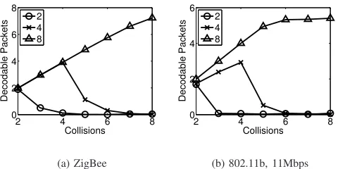
We evaluate the performance of ADOPT as we add more antennas. In the experiment, we use the deployed testbed where two to eight senders continuously transmit to the AP. We measure the average number of decoded packets by the ADOPT receiver for a given number of concurrent packets. We set all nodes to deliver similar receiving SNR to the AP. ZigBee nodes have approximately 10dB and 802.11b nodes have 15dB as SNR values. Figure 16 shows that the collided packets can be decoded with the highest probability when the number of collided packets matches the number of antennas. When it is larger than the number of antennas, the decoding performance drops quickly. With an eight-antenna ZeeBee ADOPT receiver, we can decoded up to 7.2 packets. Note that this high number of decoded packets is partly due to the ZigBee’s reliable coding scheme at the physical layer (e.g., ZigBee uses 8 times redundancy for encoding a packet compared to 802.11b 11Mbps bit rate). However with the WiFi AP, that number stops at 5 packets. This is because WiFi nodes send at 11Mbps and their SNRs are not strong enough to push the number of decoded packets beyond 5.
5.2 Performance in Testbeds
2 4 6 8 0
2 4 6 8
Collisions
Decodable Packets
2 4 8
(a) ZigBee
2 4 6 8
0 2 4 6
Collisions
Decodable Packets
2 4 8
(b) 802.11b, 11Mbps
Fig. 16. The average number of decoded packets. X-axis shows the number of concurrently transmitted packets. Different lines show the number of antennas at the re-ceiver. We vary the number of antennas from two to eight for a given number of collided packets.
Scenario CW size Hidden terminal
1 Auto No
2 Maximum 8 (16) No
3 Auto Yes
4 Maximum 8 (16) Yes
TABLE 1
Testbed evaluation scenarios.
Scenario Total tx. Single tx. Coll. Concur. tx. 1 16,061 12,620 3,441 1.25 2 16,145 9,099 7,046 1.62 3 10,729 5,106 5,623 1.90 4 21,370 1,903 19,476 3.78
TABLE 2
Packet transmission statistics in WiFi testbed during 30 seconds. The average number of collided packet
increases with the scenario index.
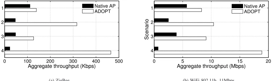
Four different scenarios are tested as follow. In scenario 1, we do not change the medium access. In scenario 2, we manually adjust the maximum size of the contention window (CWmax) to 8 in the ZigBee testbed and 16 in the WiFi testbed such that the packets are transmitted more aggressively. We also differentiate the existence of hidden terminals. In scenario 3, we increase the carrier sense threshold of nodes such that half of the nodes are hidden to the another half. We do not modify contention window in scenario 3. Finally in scenario 4, we both modify the carrier sense threshold and size of the contention window such that the number of concurrent trans-missions is maximized. The scenario setups are summarized in Table 1 and Table 2 presents the packet transmission statistics (obtained in the WiFi testbed). Each column shows the number of total packet transmission attempts, the number of single node transmissions, the number of collisions and the average number of concurrent transmissions per each transmission attempt.
Figure 17 shows the results. In scenario 1, where we do not modify any setting of standard protocols, carrier sensing
prevents nodes to transmit concurrently. ADOPT still achieves about 30% to 46% improvement over the native AP. As we force the senders to transmit more aggressively in scenario 2, more packet collisions are introduced and the performance improvement by ADOPT becomes more significant. ADOPT shows 570% higher throughput in ZigBee testbed and 340% in WiFi testbed. Note that in both scenario 1 and 2, most of the packet preambles are perfectly aligned but ADOPT can reliably decode them.
In scenario 3 and 4 where hidden terminals exist, collisions are much more common. Therefore the performance of the native AP severely degrades. In scenario 3, size of each sender’s contention window is around the maximum because of the repeated collisions. So the transmission attempts are largely discouraged. As we see from Table 2, nodes transmit the least number of packets. But the average number of collided packets per each transmission is still larger than scenario 1 and 2. By reducing theCWmax, we again push the senders to transmit more aggressively in scenario 4. Table 2 shows that the number of concurrent transmissions are doubled compared to scenario 3.
We can interpret scenario 1 and 3 as the general corporate networks. Scenario 2 and 4 are more close to the networks running MUC protocols where concurrent transmissions are largely encouraged. Without any explicit cooperation among the transmitters, ADOPT increases the throughput. It is be-cause ADOPT can decode concurrent transmissions without restriction in their collision patterns. Comparing the through-put of the native AP in scenario 1 with the throughthrough-put of ADOPT in scenario 4, we can claim that ADOPT can achieve up to 319% in ZigBee and 231% in WiFi networks.
6
RELATED
WORK
SIC[8] exploits the capture effect arising in wireless networks to decode collided packets. When two or more packets collide, a receiver first decodes a packet with the strongest signals, subtracts them from the received signals. Then it decodes the weaker ones from the residue. This process is repeated to decode all the collided packets. SIC does not necessarily utilize multiple antennas at the receiver. The biggest limiting factor of SIC is its requirement of significant signal strength differences among overlapped signals. Senet al.[14] argue that from the perspective of MAC design, the gain achievable by SIC is marginal because of the requirement.
ZigZag [6] was designed to solve the hidden-terminal prob-lem. ZigZag exploits a repeated incidence of collision by the same set of packets which can happen through retransmission by hidden terminals. While ZigZag can significantly reduce MAC layer overhead, it requires nretransmissions to decode
npackets.
IAC [3] enables MUC in a network of multiple APs even when the number of senders is larger than the number of re-ceiving antennas at an AP. For this, multiple clients cooperate to align their signals using transmit beamforming so that their transmitted packets are detected as if coming from a single source. IAC can operate even when the number of antennas in each AP can differ from each other. N+
0 100 200 300 400 500 1
2
3
4
Aggregate throughput (Kbps)
Scenario
Native AP ADOPT
(a) ZigBee
0 5 10 15 20
1
2
3
4
Aggregate throughput (Mbps)
Scenario
Native AP ADOPT
(b) WiFi 802.11b, 11Mbps
Fig. 17. Aggregate Throughput of various MUC schemes. (a) no hidden terminal. (b) hidden terminals. The APs have 8 antennas. All nodes in the testbeds are transmitting.
step further and can serve as a general framework for networks where devices having different number of antennas interoper-ate. N+
helps to fully utilize the channel by increasing the number of data streams when additional degrees of freedom are available. Additionally, N+ uses an innovative technique,
lightweight RTS/CTS, that can significantly reduce the channel training overhead. For both IAC and N+, we believe that
ADOPT can further help to improve the efficiency in obtaining the physical layer parameters.
SAM [5] implements MUC using interference nullifying, cancellation and media coordination techniques. SAM mod-ifies CSMA clients to implement a channel access that en-sures that the preamble transmissions of the collided packets are serialized so that any two or more preambles are not overlapped. While the proposed interference nullifying and cancellation is still effective, ADOPT can contribute to reduce the coordination overhead.
Aryafar et al. [22] implement a downlink MUC scheme using MIMO APs, which enables the AP to send multiple packets concurrently, each destined to a different receiver. It provides a practical implementation and an experimentation of zero forcing beamforming. ADOPT is rather an uplink solution while it solves downlink MUC.
Techniques have been suggested [15] that synchronize transmitters such that received signals at a receiver have similar physical layer characteristics (e.g., arrival time, carrier frequency offset or CSI). SourceSync [16] implements such an idea with FPGA hardware programming. This type of sender cooperation can significantly improve the quality of signals received at the receiver. Still, there could be diverse devices that do not support the cooperation and ADOPT can handle them
7
CONCLUSION AND
DISCUSSION
Current WiFi or sensor network performance in a dense net-work suffer from severe packet collisions. Many MIMO based MUC solutions have been proposed to improve the capacity. Still, there is a limitation in the way those solutions obtain es-sential information for the MIMO decoding. The coordination
is necessitated in order for the senders to transmit the packets in a way that the packet preambles are not overlapped with each other. The exclusive transmission not only lowers the channel utilization but reduces the interoperability. ADOPT is a practical solution that can work as an add-on, black box decoder that does not require such an explicit coordination between the senders. Our evaluation shows that ADOPT can achieve about 46% throughput improvement over the current WiFi and ZigBee standards. But when we are allowed to mod-ify medium access and control the contention window sizes, which is easily achieved in the driver (Aethros and TinyOS allow such a control), we can achieve over 319% throughput improvement for ZigBee and 231% for WiFi 11Mbps. ADOPT can work with any kind of MAC schemes irrespective of their ability to coordinate packet transmissions. Further ADOPT could provide a level of flexibility in designing a new MAC protocol for the concurrent transmissions because it is free from such constraints.
There are further issues that we have not discussed so far, but need some attention.
Rate adaptation: A fundamental tradeoff exists between transmission rates and the number of concurrent transmissions. When multiple packets overlap, their decodability is limited by their transmission rates since a higher data rate is more susceptible to channel errors. So, which data rate should a client send when it can also control the number of concurrent transmissions (e.g., by adjusting its contention window sizes)? We can send at a high rate by reducing the concurrency, and also vice versa; as both data rate and concurrency affect throughput, this is a difficult decision. Developing an optimal rate adaptation algorithm for MUC is an area of future research.
(a) Time domain cross corre-lation
(b) Frequency domain corre-lation and matching
Fig. 18. The FDCM technique works well with the OFDM signals (802.11a) packets.
the correlation results in time domain and frequency domain, respectively.
The steps to perform interference suppression and can-cellation over OFDM signals (802.11a/g/n) is fundamentally similar. The only difference is that bits are modulated into frequency domain symbols.
REFERENCES
[1] Y.-C. Cheng, J. Bellardo, P. Benk¨o, A. C. Snoeren, G. M. Voelker, and S. Savage, “Jigsaw: Solving the puzzle of enterprise 802.11 analysis,” inProceedings of ACM SIGCOMM, 2006.
[2] V. Shrivastava, N. Ahmed, S. Rayanchu, S. Banerjee, S. Keshav, K. Papagiannaki, and A. Mishra, “Centaur: Realizing the full potential of centralized wlans through a hybrid data path,” 2009.
[3] S. Gollakota, S. D. Perli, and D. Katabi, “Interference alignment and cancellation,” inProceedings of ACM SIGCOMM, 2009.
[4] K. C.-J. Lin, S. Gollakota, and D. Katabi, “Random access heteroge-neous mimo networks,” inProceedings of ACM SIGCOMM, 2011. [5] K. Tan, H. Liu, J. Fang, W. Wang, J. Zhang, M. Chen, and G. M.
Voellker, “SAM: Enabling practical spatial multiple access in wireless lan,” inProceedings of ACM MOBICOM, 2010.
[6] S. Gollakota and D. Katabi, “ZigZag decoding: Combating hidden terminals in wireless networks,” inProceedings of ACM SIGCOMM, 2008.
[7] K. A. Jamieson, “The softphy abstraction: From packets to symbols in wireless network design,” inPh.D Dissertation, MIT, 2008.
[8] D. Halperin, T. Anderson, and D. Wetherall, “Taking the sting out of carrier sense: Interference cancellation for wireless lans,” inProceedings of ACM MOBICOM, 2008.
[9] S. Katti, S. Gollakota, and D. Katabi, “Embracing wireless interference: Analog network coding,” inProceedings of ACM SIGCOMM, 2007. [10] Y. Zhao and S.-G. Haggman, “Sensitivity to doppler shift and carrier
frequency errors in ofdm systems-the consequences and solutions,” in Vehicular Technology Conference, 1996. ’Mobile Technology for the Human Race’., IEEE 46th, apr-1 may 1996, pp. 1564 –1568 vol.3. [11] P. Moose, “A technique for orthogonal frequency division multiplexing
frequency offset correction,”Communications, IEEE Transactions on, vol. 42, no. 10, pp. 2908 –2914, oct 1994.
[12] “IEEE standard 802.11n,” 2009. [13] “IEEE standard 802.15.4,” 2006.
[14] S. Sen, R. Roy Choudhury, and S. Nelakuditi, “CSMA/CN: Carrier sense multiple access with collision notification,” inProceedings of ACM MOBICOM, 2010.
[15] R. Mudumbai, D. R. Brown, U. Madhow, and H. V. Poor, “Distributed transmit beamforming: Challenges and recent progress,”IEEE Commu-nications Magazine, vol. 47, no. 2, pp. 102 – 110, 2009.
[16] H. Rahul, H. Hassanieh, and D. Katabi, “Sourcesync: A distributed wireless architecture for exploiting sender diversity,” inProceedings of ACM SIGCOMM, 2010.
[17] K. Tan, J. Fang, Y. Zhang, S. Chen, L. Shi, J. Zhang, and Y. Zhang, “Fine-grained channel access in wireless lan,” inProceedings of ACM SIGCOMM, 2010.
[18] S. Haykin,Adaptive Filter Theory, 4th Ed. Prentice Hall, 2001.
[19] R. Rao, S. Lang, and B. Daneshrad, “Overhead optimization in a mimo-ofdm testbed based on mmse mimo decoding,” inProceedings of IEEE VTC, 2004.
[20] I. Barhumi, G. Leus, and M. Moonen, “Optimal training design for mimo ofdm systems in mobile wireless channels,”IEEE Transaction on Signal Processing, vol. 51, no. 6, pp. 1615–1624, June 2003. [21] D. Tse and P. V. Fundamentals, “Fundamentals of wireless
communica-tion, cambridge university press, 2005.” inCambridge University Press, 2005.
[22] E. Aryafar, N. Anand, T. Salonidis, and E. W. Knightly, “Design and experimental evaluation of multi-user beamforming in wireless lans,” in Proceedings of ACM MOBICOM, 2010.

![Fig. 9.There is always at least one RLS-decodablepacket in any overlapping set. A packet with the latest timeinterval [p′, p] is always RLS-decodable.](https://thumb-us.123doks.com/thumbv2/123dok_us/1204038.1151185/7.612.320.557.52.134/fig-rls-decodablepacket-overlapping-packet-latest-timeinterval-decodable.webp)