61200704L2-1B
System Manual
4200704L2#ATM Total Access 544R ATM
1200704L3 Total Access 544R without Power Cord 4200704L8 Total Access 544R with Euro Power Cord
4200704L9 Total Access 544R Total Access 544R with UK Power Cord 4200704L10 Total Access 544R with Australian Power Cord
Trademarks
Any brand names and product names included in this manual are trademarks, registered trademarks, or trade names of their respective holders.
To the Holder of the Manual
The contents of this manual are current as of the date of publication. ADTRAN reserves the right to change the contents without prior notice.
In no event will ADTRAN be liable for any special, incidental, or consequential damages or for commercial losses even if ADTRAN has been advised thereof as a result of issue of this publication.
About this Manual
This manual provides a complete description of the Total Access 544R system and system software. The purpose of this manual is to provide the technician, system administrator, and manager with general and specific information related to the planning, installation, operation, and maintenance of the Total Access 544R. This manual is arranged so that needed information can be quickly and easily found.
901 Explorer Boulevard P.O. Box 140000 Huntsville, AL 35814-4000
Phone: (256) 963-8000
© 2003 ADTRAN, Inc. All Rights Reserved.
Revision History
This is the second issue of this manual.
Conventions
Notes provide additional useful information.
Cautions signify information that could prevent service interruption.
Safety Instructions
When using your telephone equipment, please follow these basic safety precautions to reduce the risk of fire, electrical shock, or personal injury:
1. Do not use this product near water, such as a bathtub, wash bowl, kitchen sink, laundry tub, in a wet basement, or near a swimming pool.
2. Avoid using a telephone (other than a cordless-type) during an electrical storm. There is a remote risk of shock from lightning.
3. Do not use the telephone to report a gas leak in the vicinity of the leak.
4. Use only the power cord, power supply, and/or batteries indicated in the manual. Do not dispose of batteries in a fire. They may explode. Check with local codes for special disposal instructions.
Federal Communications Commission Radio Frequency Interference Statement
This equipment has been tested and found to comply with the limits for a Class A digital device, pursuant to Part 15 of the FCC Rules. These limits are designed to provide reasonable protection against harmful interference when the equipment is operated in a commercial environment. This equipment generates, uses, and can radiate radio frequency energy and, if not installed and used in accordance with the
instruction manual, may cause harmful interference to radio frequencies. Operation of this equipment in a residential area is likely to cause harmful interference in which case the user will be required to correct the interference at his own expense.
Shielded cables must be used with this unit to ensure compliance with Class A FCC limits.
Affidavit Requirements for Connection to Digital Services
• An affidavit is required to be given to the telephone company whenever digital terminal equipment without encoded analog content and billing protection is used to transmit digital signals containing encoded analog content which are intended for eventual conversion into voiceband analog signals and transmitted on the network.
• The affidavit shall affirm that either no encoded analog content or billing information is being transmitted or that the output of the device meets Part 68 encoded analog content or billing protection specifications.
• End user/customer will be responsible for filing an affidavit with the local exchange carrier when connecting unprotected customer premise equipment (CPE) to 1.544 Mbps or subrate digital services. • Until such time as subrate digital terminal equipment is registered for voice applications, the affidavit
Affidavit for Connection of Customer Premises Equipment to 1.544 Mbps and/or Subrate Digital Services
For the work to be performed in the certified territory of ___________________ (telco name) State of ________________
County of ________________
I, _______________________ (name), ____________________________________ (business address), ____________________ (telephone number) being duly sworn, state:
I have responsibility for the operation and maintenance of the terminal equipment to be connected to 1.544 Mbps and/or ________ subrate digital services. The terminal equipment to be connected complies with Part 68 of the FCC rules except for the encoded analog content and billing protection specifications. With respect to encoded analog content and billing protection:
I attest that all operations associated with the establishment, maintenance, and adjustment of the digital CPE with respect to analog content and encoded billing protection information continuously complies with Part 68 of the FCC Rules and Regulations.
The digital CPE does not transmit digital signals containing encoded analog content or billing information which is intended to be decoded within the telecommunications network.
The encoded analog content and billing protection is factory set and is not under the control of the customer.
I attest that the operator(s)/maintainer(s) of the digital CPE responsible for the establishment, maintenance, and adjustment of the encoded analog content and billing information has (have) been trained to perform these functions by successfully having completed one of the following (check appropriate blocks):
A training course provided by the manufacturer/grantee of the equipment used to encode analog signals; or
A training course provided by the customer or authorized representative, using training materials and instructions provided by the manufacturer/grantee of the equipment used to encode analog signals; or
An independent training course (e.g., trade school or technical institution) recognized by the manufacturer/grantee of the equipment used to encode analog signals; or
In lieu of the preceding training requirements, the operator(s)/maintainer(s) is (are) under the control of a supervisor trained in accordance with _________ (circle one) above.
I agree to provide ______________________ (telco’s name) with proper documentation to demonstrate compliance with the information as provided in the preceding paragraph, if so requested.
This ________ day of _______________, _______
_________________________________ Notary Public
My commission expires:
Industry Canada Compliance Information
Notice: The Industry Canada label applied to the product (identified by the Industry Canada logo or the “IC:” in front of the certification/registration number) signifies that the Industry Canada technical specifications were met.
Notice: The Ringer Equivalence Number (REN) for this terminal equipment is supplied in the
documentation or on the product labeling/markings. The REN assigned to each terminal device indicates the maximum number of terminals that can be connected to a telephone interface. The termination on an interface may consist of any combination of devices subject only to the requirement that the sum of the RENs of all the devices should not exceed five (5).
Canadian Emissions Requirements
This digital apparatus does not exceed the Class A limits for radio noise emissions from digital apparatus as set out in the interference-causing equipment standard entitled “Digital Apparatus,” ICES-003 of the Department of Communications.
Product Warranty
ADTRAN will replace or repair this product within the warranty period if it does not meet its published specifications or fails while in service. Warranty information can be found at www.adtran.com/warranty.
Product Registration
Registering your product helps ensure complete customer satisfaction. Please take time to register your products on line at www.adtran.com. Click Service and Support on the top of the page, and then click
Product Registration under Support.
Customer Service, Product Support Information, and Training
ADTRAN will replace or repair this product within the warranty period if it does not meet its published specifications or fails while in service. Warranty information can be found at www.adtran.com/warranty. A return material authorization (RMA) is required prior to returning equipment to ADTRAN. For service, RMA requests, training, or more information, use the contact information given below.
Repair and Return
If you determine that a repair is needed, please contact our Customer and Product Service (CAPS) department to have an RMA number issued. CAPS should also be contacted to obtain information regarding equipment currently in house or possible fees associated with repair.
Identify the RMA number clearly on the package (below address), and return to the following address:
Pre-Sales Inquiries and Applications Support
Your reseller should serve as the first point of contact for support. If additional pre-sales support is needed, the ADTRAN Support web site provides a variety of support services such as a searchable knowledge base, latest product documentation, application briefs, case studies, and a link to submit a question to an Applications Engineer. All of this, and more, is available at:
When needed, further pre-sales assistance is available by calling our Applications Engineering Department.
CaPS Department (256) 963-8722
ADTRAN Customer and Product Service 901 Explorer Blvd. (East Tower)
Huntsville, Alabama 35806 RMA # _____________
http://support.adtran.com
Post-Sale Support
Your reseller should serve as the first point of contact for support. If additional support is needed, the ADTRAN Support web site provides a variety of support services such as a searchable knowledge base, updated firmware releases, latest product documentation, service request ticket generation and
trouble-shooting tools. All of this, and more, is available at:
When needed, further post-sales assistance is available by calling our Technical Support Center. Please have your unit serial number available when you call.
Installation and Maintenance Support
The ADTRAN Custom Extended Services (ACES) program offers multiple types and levels of installation and maintenance services which allow you to choose the kind of assistance you need. This support is available at:
For questions, call the ACES Help Desk.
Training
The Enterprise Network (EN) Technical Training Department offers training on our most popular products. These courses include overviews on product features and functions while covering applications of
ADTRAN's product lines. ADTRAN provides a variety of training options, including customized training and courses taught at our facilities or at your site. For more information about training, please contact your Territory Manager or the Enterprise Training Coordinator.
http://support.adtran.com
Technical Support (888) 4ADTRAN
http://www.adtran.com/aces
ACES Help Desk (888) 874-ACES (2237)
Training Phone (800) 615-1176, ext. 7500 Training Fax (256) 963-6700
Section 1
System Description . . . 15
This section of ADTRAN’s Product System Manual is designed for use by network engineers, planners, and designers for overview information about the Product. It contains general information and describes the L2 protocol support, routing capability, secu-rity, and testing features. This section should be used in conjunction with Section 2, Engineering Guidelines, of this System Manual.
Section 2
Engineering Guidelines . . . 19
Provides equipment dimensions, power requirements, front panel design, rear panel design, LEDs, and at-a-glance specifications.
Section 3
Network Turnup Procedure . . . 25
Provides shipment contents list, grounding instructions, mounting options, and specifics of sup-plying power to the unit.
Section 4
SHDSL RCU ATM User Interface Guide . . . 29
The SHDSL RCU ATM User Interface Guide is designed for use by network administrators and others who will configure and provision the system. This section provides details unique to the SHDSL RCU ATM firmware. It contains an overview, application details, configuration infor-mation, and menu
Section 5
Detail Level Procedures. . . 95
DLP-1 Connecting the Terminal or PC to the CRAFT Port . . . 97
DLP-2 Logging in to the System . . . 101
DLP-3 Adding/Removing Telnet Users and Changing Password Security Levels . . . 105
DLP-4 Setting Ethernet IP Parameters . . . 109
DLP-5 Verifying Communications Over an IP LAN . . . 111
DLP-6 Telnetting to the Unit . . . 115
DLP-7 Upgrading the Firmware Using XMODEM . . . 119
DLP-8 Upgrading the Firmware Using TFTP . . . 121
DLP-9 Saving the Current Configuration Using TFTP . . . 125
DLP-10 Loading the Current Configuration Using TFTP . . . 129
DLP-11 Saving the Current Configuration Using XMODEM . . . 133
DLP-12 Loading the Current Configuration Using XMODEM . . . 135
DLP-13 Saving and Loading Text Configuration Using the Terminal Command Line. . . 137
DLP-14 Unit Installation Using The Auto-Config Feature. . . 141
DLP-15 A.03 to A.04 Firmware Upgrade. . . 145
Section 6
ADTRAN Utilities . . . 149
Provides instructions for configuring and using the ADTRAN Utilities software programs in-cluding Telnet, VT100, Syslog, and TFTP.
Section 7
MIBs. . . 159
This section of ADTRAN’s Product System Manual is designed for use by network engineers, planners, and designers for overview information about the Product.
It contains general information and describes the L2 protocol support, routing capability, security, and testing features. This section should be used in conjunction with Section 2, Engineering Guidelines, of this System Manual.
C
ONTENTSFirmware Updates. . . 16
Terminal Menu . . . 16
Features and Benefits . . . 16
Configuration and Management . . . 16
Software Upgradeable . . . 17
Network Interface . . . 17
LAN Interface . . . 17
Protocol Support . . . 17
ATM Support . . . 18
PPP . . . 18
Routing Capability . . . 18
Security . . . 18
1.
SYSTEM OVERVIEW
The Total Access 544R is a cost-effective SHDSL access router designed for small and medium
businesses, branch offices and campuses. The unit provides up to 2312 kbps for dedicated Internet access or remote office connectivity. With its integrated CSU/DSU, the Total Access 544R provides wide area network access over a standard SHDSL or fractional SHDSL circuit.
Multiple users can share network access over a single SHDSL connection. For simultaneous access to both a corporate network and the public Internet, the unit offers the ability to configure multiple PVCs. In addition, the unit includes NAT/NAPT and IP filtering which provides security from unauthorized access to the user's network.
The Total Access 544R also provides a cost-effective campus connectivity solution. When used with private dry copper, the unit delivers up to 2.3 Mbps to cross-campus network elements. This solution is ideal for extending LAN segments to other buildings.
Other features include a DHCP server, TELNET support, SNMP support, ping utility, and software upgrades via TFTP and XMODEM.
Until now, the Total Access 544R unit has been running firmware version A.00.XX. Recently, D.04.XX has been released. The development of D.04.XX code is a significant step in the evolution of the Total Access product line, as it allows all Total Access family members to share the same base code. This means that features and fixes are more easily implemented and are propagated across the product line. Section 4,
SHDSL ATM User Interface Guide, of this manual represents the D.04 firmware.
Firmware Updates
Firmware can be updated by using XMODEM transfer protocol via the unit’s CRAFT port or by using TFTP from a network server.
Terminal Menu
The terminal menu is the access point to all other operations. Each terminal menu item has several functions and submenus that identify and provide access to specific operations and parameters. These menu selections are described later in this System Manual.
2.
FEATURES AND BENEFITS
Below is a list of unit features and benefits.
Configuration and Management
• VT100 emulation via the CRAFT port • Telnet• SNMP
• LAN and WAN status LEDs
• ICMP Ping utility • Trace route utility
Software Upgradeable
• TFTP download• XMODEM via CRAFT port
Network Interface
G.shdsl: (ITU G.991.2 Compliant)
• Line Rate: 200- 2312 kbps (3-36 DS0s) • Physical Interface: RJ-48C
• Rate Adaptive
• Improved Spectral Compatibility • Echo Cancellation
LAN Interface
• 10/100 BaseT • Half or Full Duplex • RJ-45• Secondary IP address • DHCP server
• IEEE 802.3
Protocol Support
• IP• DNS
• TCP
• RIP V1, V2 and static routes • UDP, UDP Relay
• ICMP
• ARP
• PPP
ATM Support
• 6 PVCs• IP over ATM (RFC 1483)
• RFC 1483 (Multiprotocol Encapsulation over ATM), PPPoA (RFC 2364) • Full Traffic Shaping and QoS Support
• VBR-rt and UBR Support • F5 OAM Loopback Capability
PPP
• LCP, IPCP, BCP, CCP
• Van Jacobson (VJ) header compression
Routing Capability
• Ethernet: 10/100BaseT (RJ-45)
• IEEE 802.3 and 802.1D (MAC Bridging)
• IP Support: TCP, RIP V1, RIP V2, UDP, ICMP, ARP, UDP Relay, SYSLOG • PPP Support: LCP, IPCP, BCP
• DHCP Server to LAN, DHCP from network (NAT)
Security
• PAP, CHAP, EAP, and Radius
• NAT/NAPT
• Packet filtering by source and destination IP address, source and destination port number, MAC address, protocol or pattern
• Multi-layer Password protection
• Telnet security: Access list and password protection
Integrated Components
• IP routerProvides equipment dimensions, power requirements, front panel design, rear panel design, LEDs, and at-a-glance specifications.
C
ONTENTSReviewing the Front Panel Design . . . 20
Front Panel LEDs . . . 20
Reviewing the Rear Panel Design . . . 21
NTWK Connection (RJ-48C). . . 21
CRAFT Port (RJ-48C) . . . 21
10/100BASET Connection (RJ-48C). . . 22
AC Power Connection. . . 22
DB-9 to RJ Adapter . . . 23
F
IGURES Figure 1. Total Access 544R Front Panel Layout . . . 20Figure 2. Total Access 544R Rear Panel . . . 21
T
ABLES Table 1. Total Access 544R Front Panel LEDs . . . 20Table 2. SHDSL NTWK Connection Pinout . . . 21
Table 3. CRAFT Pinout . . . 22
Table 4. 10/100BASET Pinout . . . . 22
Table 5. DB-9 to RJ Adapter Pinout . . . 23
E
QUIPMENTD
IMENSIONS1.
POWER REQUIREMENTS
The Total Access 544R operates with 240 VAC, 50 Hz and a maximum current drain of 300 mA. The Total Access 544R maximum power consumption shall not exceed 10 Watts.
2.
REVIEWING THE FRONT PANEL DESIGN
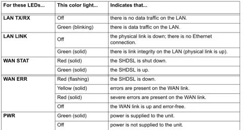
Figure 1. shows the front panel of the Total Access 544R which contains the LAN, WAN, and power LEDs. These LEDs and their functions are described in Table 1.
.
Figure 1. Total Access 544R Front Panel Layout
Front Panel LEDs
The front panel provides five status LEDs to monitor operation and activity. The following table provides LED activity explanations.
Table 1. Total Access 544R Front Panel LEDs For these LEDs... This color light... Indicates that...
LAN TX/RX Off there is no data traffic on the LAN.
Green (blinking) there is data traffic on the LAN.
LAN LINK Off the physical link is down; there is no Ethernet connection.
Green (solid) there is link integrity on the LAN (physical link is up).
WAN STAT Red (solid) the SHDSL is shut down.
Green (solid) the SHDSL is up.
WAN ERR Red (flashing) the SHDSL is down.
Yellow (solid) errors are present on the WAN link. Red (solid) severe errors are present on the WAN link. Off the WAN link is up and error-free.
PWR Green (solid) power is supplied to the unit.
Off power is not supplied to the unit.
3.
REVIEWING THE REAR PANEL DESIGN
The Total Access 544R rear panel is shown in Figure 2..
Figure 2. Total Access 544R Rear Panel
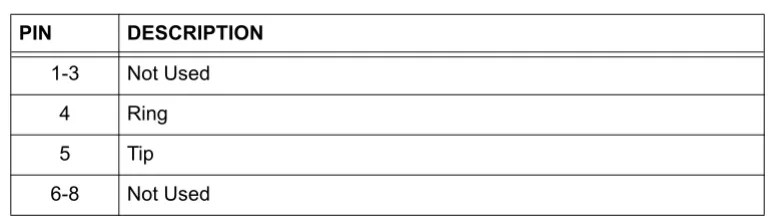
NTWK Connection (RJ-48C)
The NTWKconnection pinout is an SHDSL connection. Table 1 shows the pinout for this connection.
CRAFT Port (RJ-48C)
The CRAFT port connects to a computer or modem. The CRAFT port input provides the following functions:
• Accepts input from a PC or a modem for controlling the unit.
• Operates at 300, 1200, 2400, 4800, 9600, 19200, 38400, 57600, and 115200 bps. • Acts as input for either VT100 or PC control.
• Acts as an interface for flash memory software downloads using XMODEM.
Table 3 shows the CRAFT port pinout.
Connector type RJ-48C
Table 2. SHDSL NTWK Connection Pinout
PIN DESCRIPTION
1-3 Not Used
4 Ring
5 Tip
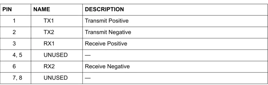
10/100BASET Connection (RJ-48C)
The 10/100BASET port (RJ-48C) provides a 10/100BaseT Ethernet LAN connection, which is used for IP Routing, TFTP, SNMP, and Telnet connections. Table 4 shows the 10/100BASET port pinout.
AC Power Connection
Each unit includes an auto ranging 100-250 VAC, 50/60 Hz power supply with a 3-prong removable cable. Connect the power supply to a standard 120 VAC, 60 Hz electrical outlet for proper operation.
Table 3. CRAFT Pinout
PIN NAME DESCRIPTION
1 GND Ground - connected to unit chassis
2 RTS Request to send - flow control
3 RXDATA Data received by the unit.
4 DTR Data terminal ready
5 TXDATA Data transmitted by the unit.
6 CD Carrier detect
7 UNUSED —
8 CTS Clear to send - flow control
Table 4. 10/100BASET Pinout
PIN NAME DESCRIPTION
1 TX1 Transmit Positive
2 TX2 Transmit Negative
3 RX1 Receive Positive
4, 5 UNUSED —
6 RX2 Receive Negative
4.
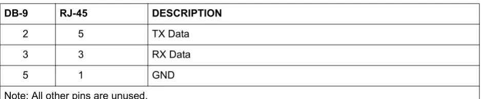
DB-9 TO RJ ADAPTER
The DB-9 to RJ adapter is used to connect a PC or VT100 terminal to the CRAFT port. The adapter pinout is shown in Table 5.
Table 5. DB-9 to RJ Adapter Pinout
DB-9 RJ-45 DESCRIPTION
2 5 TX Data
3 3 RX Data
5 1 GND
Provides shipment contents list, grounding instructions, mounting options, and specifics of supplying power to the unit.
C
ONTENTS1.
INTRODUCTION
This section discusses the unit installation process.
2.
TOOLS REQUIRED
The tools required for unit installation are:
• Screws (customer-provided for wallmount installation) • Screwdriver (for wall or rackmount installation)
3.
UNPACK AND INSPECT THE SYSTEM
Each unit is shipped in its own cardboard shipping carton. Open each carton carefully and avoid deep penetration into the carton with sharp objects.
After unpacking the unit, inspect it for possible shipping damage. If the equipment has been damaged in transit, immediately file a claim with the carrier, and then contact ADTRAN Customer Service (see the contact information in the front of this manual).
Contents of ADTRAN Shipment
Your ADTRAN shipment of the Total Access 544R includes the following items: • Mounting Instructions (P/N 64200600L1#T-19A)
• CD
• Cable Tie (P/N 3292032)
• Silver Satin Cable (P/N 3127004) • Four Rubber Feet (P/N 3270BF003) • Power Cord (P/N 3127009)
• 2 Mounting Brackets (P/N 3265421@C)
To prevent electrical shock, do not install equipment in a wet location or during a lightning storm.
During installation, power should be the last connection made.
• 4 Screws (P/N 3276003003)
• RJ-45 to DB-9 Adapter (P/N 3196ADPT001) • The Total Access 544R base unit
4.
GROUNDING INSTRUCTIONS
The following provides grounding instruction information from the Underwriters’ Laboratory UL60950 Standard for Safety of Information Technology Equipment Including Electrical Business Equipment, Third Edition, of December 1, 2000.
An equipment grounding conductor that is not smaller in size than the ungrounded branch-circuit supply conductors is to be installed as part of the circuit that supplies the product or system. Bare, covered, or insulated grounding conductors are acceptable. Individually covered or insulated equipment grounding conductors shall have a continuous outer finish that is either green, or green with one or more yellow stripes. The equipment grounding conductor is to be connected to ground at the service equipment.
The attachment-plug receptacles in the vicinity of the product or system are all to be of a grounding type, and the equipment grounding conductors serving these receptacles are to be connected to earth ground at the service equipment.
A supplementary equipment grounding conductor shall be installed between the product or system and ground that is in addition to the equipment grounding conductor in the power supply cord.
The supplementary equipment grounding conductor shall not be smaller in size than the ungrounded branch-circuit supply conductors. The supplementary equipment grounding conductor shall be connected to the product at the terminal provided, and shall be connected to ground in a manner that will retain the ground connection when the product is unplugged from the receptacle. The connection to ground of the supplementary equipment grounding conductor shall be in compliance with the rules for terminating bonding jumpers at Part K or Article 250 of the National Electrical Code, ANSI/NFPA 70. Termination of the supplementary equipment grounding conductor is permitted to be made to building steel, to a metal electrical raceway system, or to any grounded item that is permanently and reliably connected to the electrical service equipment ground.
The supplemental grounding conductor shall be connected to the equipment using a number 8 ring terminal and should be fastened to the grounding lug provided on the rear panel of the equipment. The ring terminal should be installed using the appropriate crimping tool (AMP P/N 59250 T-EAD Crimping Tool or equivalent).
Customers must supply the Ethernet cable.
• This unit shall be installed in accordance with Article 400 and 364.8 of the NEC NFPA 70 when installed outside of a Restricted Access Location (i.e., central office, behind a locked door, service personnel only area).
5.
SUPPLYING POWER TO THE UNIT
The AC powered unit comes equipped with a detachable power cord with a 3-prong plug for connecting to a grounded power receptacle. As shipped, the unit is set to factory default conditions. After installing the chassis, the unit is ready for power-up. To power-up the unit, ensure that the unit is properly connected to an appropriate power source.
6.
MOUNTING OPTIONS
The Total Access 544R comes equipped for table top or wallmount use. The unit is shipped with two wall-mount brackets (P/N 326542@C) and four screws (P/N 3276003003) which the customer must attach to the base unit for wallmount use.
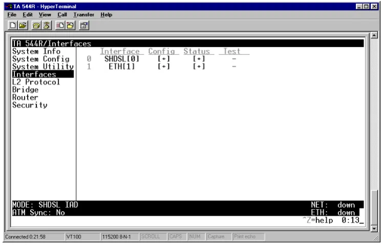
The SHDSL RCU ATM User Interface Guide is designed for use by network administrators and others who will configure and provision the system. This section provides details unique to the SHDSL RCU ATM firmware. It contains an overview, application details, configuration information, and menu
C
ONTENTSSystem Info . . . 30 System Config. . . 32 System Utility . . . 46 Interfaces (SHDSL) . . . 53 Interfaces (ETH) . . . 55 L2 Protocol . . . 56 L2 Protocol (SHDSL). . . 56 L2 Protocol (ETH) . . . 63 Bridge . . . 65 Router . . . 67 Security . . . 83
F
IGURESFigure 1. System Info Menu . . . 30 Figure 2. System Config Menu . . . 32 Figure 3. System Utility Menu . . . 46 Figure 4. Interfaces Menu . . . 53 Figure 5. L2 Protocol Menu . . . 56 Figure 6. Bridge Menu. . . 66 Figure 7. Router Menu . . . 68 Figure 8. Security Menu . . . 83 Figure 9. Application Diagrams . . . 90
T
ABLES1.
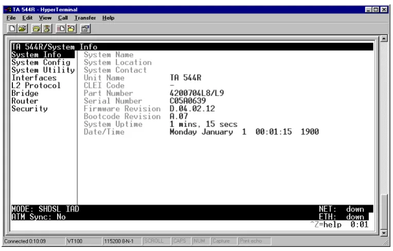
SYSTEM INFO
The System Info menu provides basic information about the unit as well as data fields for editing information. Figure 1 displays the submenus that are available when you select this menu item.
Figure 1. System Info Menu
S
YSTEMI
NFO> S
YSTEMN
AMEProvides a user-configurable text string for the name of the unit. This name can help you distinguish between different installations. You can enter up to 31 alpha-numeric characters in this field, including spaces and special characters (such as an underscore). This name will appear on the top line of all screens. This field is blank by default.
S
YSTEMI
NFO> S
YSTEML
OCATIONProvides a user-configurable text string for the location of the unit. This field is to help you keep track of the actual physical location of the unit. You can enter up to 31 alphanumeric characters in this field, including spaces and special characters (such as an underscore). This field is blank by default.
S
YSTEMI
NFO> S
YSTEMC
ONTACTS
YSTEMI
NFO> U
NITN
AMEProduct-specific name for the unit.
S
YSTEMI
NFO> CLEI C
ODEThe CLEI code for the unit.
S
YSTEMI
NFO> P
ARTN
UMBERADTRAN part number for the unit.
S
YSTEMI
NFO> S
ERIALN
UMBERThe serial number field will reflect serial number located on bottom of the unit’s chassis.
S
YSTEMI
NFO> F
IRMWARER
EVISIONDisplays the current firmware revision level of the unit.
S
YSTEMI
NFO> B
OOTCODER
EVISIONDisplays the bootcode revision.
S
YSTEMI
NFO> S
YSTEMU
PTIMEDisplays the length of time since the last reboot of the unit.
S
YSTEMI
NFO> D
ATE/T
IMEDisplays the current date and time, including seconds. This field can be edited. Enter the time in 24-hour format (such as 23:00:00 for 11:00 pm). Enter the date in mm-dd-yyyy format (for example, 10-30-1998).
S
YSTEMC
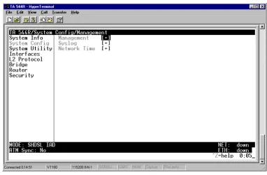
ONFIGSet up the unit’s operational configuration from the SYSTEM CONFIG menu. Figure 3 shows the items included in this menu.
Figure 2. System Config Menu
S
YSTEMC
ONFIG> M
ANAGEMENTSet up the CRAFTPORT, TELNET ACCESS, SNMP MANAGEMENT, and FDL MANAGEMENT from this menu.
S
YSTEMC
ONFIG> M
ANAGEMENT> CRAFT P
ORTSet up the CRAFT PORT parameters from this menu.
S
YSTEMC
ONFIG> M
ANAGEMENT> CRAFT P
ORT> P
ASSWORDP
ROTECTThe unit’s VT100 CRAFT port can be accessed via an RJ-48C connector located on the rear of the unit, or the DB-9 connector on the front of the unit.
When PASSWORD PROTECTis set to NO, the CRAFT port is not password protected. When YES (def), the unit will prompt for a password upon startup.
S
YSTEMC
ONFIG> M
ANAGEMENT> CRAFT P
ORT> P
ASSWORDS
YSTEMC
ONFIG> M
ANAGEMENT> C
RAFTP
ORT> I
DLET
IMEThis option defines the amount of time in minutes user may stay connected without any activity on the
CRAFT port before the user is automatically logged out of the system. A value of 0 disables this inactivity timer function enabling users to stay connected until manually logged out. The value range is 0 (def) to
255 (min).
S
YSTEMC
ONFIG> M
ANAGEMENT> CRAFT P
ORT> B
AUDR
ATEThis is the asynchronous rate that the CRAFT port will run. The possible values are 300, 1200, 2400, 4800,
9600, 19200, 38400, 57600, and 115200. The default value is 9600.
S
YSTEMC
ONFIG> M
ANAGEMENT> CRAFT P
ORT> D
ATAB
ITSThis is the asynchronous bit rate that the CRAFT port will run. The possible values are 7 or 8 (def) bits.
S
YSTEMC
ONFIG> M
ANAGEMENT> CRAFT P
ORT> P
ARITYThis is the asynchronous parity that the CRAFT port will run. The possible values are NONE (def), ODD, or
EVEN.
S
YSTEMC
ONFIG> M
ANAGEMENT> CRAFT P
ORT> S
TOPB
ITSThis is the number of stop bits used for the CRAFT port. The possible values are 1 (def), 1.5 or 2.
S
YSTEMC
ONFIG> M
ANAGEMENT> T
ELNETA
CCESSThe security level for the CRAFT port is always set to FULL. This gives full access to all
menus.
Passwords are case-sensitive and can contain up to 30 alphanumeric characters (including spaces and special characters).
Table 1. Instructions for Changing Passwords
Step Action
1 Select the PASSWORD field—a new PASSWORD field displays.
2 Type the new password in the ENTER field.
S
YSTEMC
ONFIG> M
ANAGEMENT> T
ELNETA
CCESS> A
CCESSSets ACCESS to ON or OFF. The factory default value for this parameter is ON.
S
YSTEMC
ONFIG> M
ANAGEMENT> T
ELNETA
CCESS> A
UTHENM
ETHODSet up the telnet authentication method from this menu. The choices are PASSWORD, RADIUS,
PASSWORD/RADIUS, and RADIUS/PASSWORD. PASSWORD/RADIUS indicates that the unit will try Password Authentication first and if that fails, it will try Radius Authentication. RADIUS/PASSWORD indicates that the unit will try Radius authentication first and if that fails, it will try Password authentication. The default is
PASSWORD.
S
YSTEMC
ONFIG> M
ANAGEMENT> T
ELNETA
CCESS> U
SERL
ISTAdd telnet users and control the telnet access conditions through this menu.
#
Display the index number of the telnet users. Up to four users can be configured for access to the unit. Each user can be assigned a security level and idle time.
NAME
The name is a text string of the user name for this session. You can enter up to 15 characters in this field. The factory default is no entry in the NAME field
PASSWORD
When the authenticating method is password, or password radius, this text string is used for the password. You can enter up to 30 characters in this field. The factory default is no entry in this field.
IDLE TIME (MINS)
This sets the amount of time in minutes you can be idle before you are automatically logged off. The factory default is 10 MINUTES. The range is 1-255 minutes.
LEVEL
S
YSTEMC
ONFIG> M
ANAGEMENT> T
ELNETA
CCESS> IP A
CCESSL
ISTSet up the list of allowed telnet managers.
Table 2. Telnet Security Levels Security
Level Description
Full The user has all access to view and configure all menus (same as logging in to the CRAFT port)
Support The user has read only access to view the SYSTEM INFO menu. The user has
privileges to view and change everything under the SYSTEM CONFIG menu
except for the CRAFT port settings, telnet access lists, and the SNMP management communities. The user has full access to the SYSTEM UTILITY
menu, including the ability to upgrade firmware and reset the unit. The user has full access to the INTERFACES, L2 PROTOCOL, BRIDGE, ROUTER, and DS0 menus.
The user does not have the ability to set RADIUSSERVER settings under the
SECURITY menu.
Config The same privileges as support, except that the user does not have privileges to download firmware or configuration from the SYSTEM UTILITY menu. The user
additionally does not have the privilege to reset the unit remotely, or enter the terminal menu.
Router The user has read only privileges for the SYSTEM INFO menu. There is no access
to the SYSTEM CONFIG menu. The user has PING and TRACEROUTE access from
the SYSTEM UTILITY menu. The user is limited to ethernet configuration and
status from the INTERFACES menu. The user has full access to the BRIDGE and
ROUTER menus. Access is limited to filters only from the SECURITY menu.
Voice The user has read only privileges for the SYSTEM INFO menu. The user has
access to the PING and TRACEROUTE utilities from the SYSTEM UTILITIES menu.
The user has full access to the FXS module from the INTERFACES menu.
Status The user has read access of all menus except for the following: SYSTEM
CONFIG/CRAFT PORT, SYSTEM CONFIG/TELNET ACCESS, SYSTEM CONFIG/SNMP
MANAGEMENT, and SECURITY/ RADIUS SERVER. The user does not have access
to UPGRADE FIRMWARE, UPGRADE CONFIG, PING, or TRACEROUTE menus. The
user cannot reset the unit or enter terminal mode.
NETWORK ADDRESSAND MASK
Enter a network address and subnet mask from which telnet access to the unit is allowed. When a remote unit requests telnet access to the unit, if the access list is empty or the remote’s IP address matches a list entry, remote access is granted. A subnet mask of 0.0.0.0 will allow any host telnet access, regardless of the network address. A network address of 0.0.0.0 with corresponding netmask 255.255.255.255 will not allow any host telnet access.
S
YSTEMC
ONFIG> M
ANAGEMENT> SNMP M
ANAGEMENTAccess the SNMP management and configure the SNMP communities and traps from this menu.
S
YSTEMC
ONFIG> M
ANAGEMENT> SNMP M
ANAGEMENT> A
CCESSWhen set to OFF, SNMP access is denied. When set to ON, the unit will respond to SNMP managers based on the configuration. The factory default is ON.
S
YSTEMC
ONFIG> M
ANAGEMENT> SNMP M
ANAGEMENT>T
RAPD
ELAYTime in seconds that represents the delay inserted between the trap creation and trap transmission. The range is 0 to 600 seconds. The factory default is 0 SEC.
S
YSTEMC
ONFIG> M
ANAGEMENT> SNMP M
ANAGEMENT> C
OMMUNITIESSet up the SNMP communities parameters from this menu.
#
Displays the index number of the SNMP Communities.
This list is used to set up to 8 SNMP communities that the unit will allow.
NAME
This is the text string used to identify the SNMP community. This field is blank by default.
PRIVILEGE
The access for this manager can be assigned three levels. The factory default is NONE.
NONE No access is allowed for this community or manager.
GET Manager can only read items.
GET/SET Manager can read and set items.
MANAGER IP
S
YSTEMC
ONFIG> M
ANAGEMENT> SNMP M
ANAGEMENT> T
RAPSSets up the trap manager name and IP from this menu.
S
YSTEMC
ONFIG> M
ANAGEMENT> FDL M
ANAGEMENTEnables the FDL management and configures mode and IP addresses from this menu.
S
YSTEMC
ONFIG> M
ANAGEMENT> FDL M
ANAGEMENT> M
ODEThis enables the FDL (only in ESF mode) to be used for management. Learning mode can also be enabled so the unit can "learn" its IP configuration to be used for its FDL management. Once it learns this
information from, for example a Total Access 4303, the configuration items populate. The factory default is ON.
S
YSTEMC
ONFIG> M
ANAGEMENT> FDL M
ANAGEMENT> L
INKIP A
DDRESSThis is the local IP address used for FDL management. The FDL uses a separate IP network for
communication, distinct from the customer data that is configured under the Router menus. The factory default is 0.0.0.0.
S
YSTEMC
ONFIG> M
ANAGEMENT> FDL M
ANAGEMENT> IP N
ETMASKThis is the subnet mask defining the IP network used for FDL management. The factory default is 0.0.0.0.
NETMASK
The mask is used to determine which bits of the MANAGER IP are significant. A "0" bit means "don't care." A "1" bit means that the corresponding address bits in the incoming SNMP packet must match the address bit in the defined MANAGER IP. The netmask of 255.255.255.255 defines a single IP as the manager host IP. The default value is 0.0.0.0.
#
Displays the index number in the SNMP traps table.
This list allows up to 20 managers to be listed to receive traps.
MANAGER NAME is the text string describing the name of the entry. It is intended for easy reference and has no bearing on the SNMP trap function. You can enter up to 31 characters in this field. The factory default is no entry in the manager name field.
MANAGER IP
S
YSTEMC
ONFIG> M
ANAGEMENT> FDL M
ANAGEMENT> F
AR-E
NDIP A
DDRESSThis is the far-end IP address used for the FDL management. The FDL is a separate IP network from the customer data that is configured under the Router menus. The factory default is 0.0.0.0.
S
YSTEMC
ONFIG> M
ANAGEMENT> FDL M
ANAGEMENT> L
EARNA
DDRESSWhen set to ON, the destination address on each received packet is assumed to be the FDL interface address. A 255.255.255.252 netmask is used, which determines the far-side address as well (since there can be only two addresses on a subnet with that netmask). When set to OFF, the user must input the IP address assigned to the FDL interface. Default is ON.
S
YSTEMC
ONFIG> M
ANAGEMENT> FDL M
ANAGEMENT> A
CCEPTA
LLSNMP
When set to ON, SNMP gets/sets received over the FDL link are always accepted regardless of the community table. When set to OFF, the community table is searched for valid manager IP addresses and the SNMP traffic is rejected if a match is not found. Default is ON.
S
YSTEMC
ONFIG> M
ANAGEMENT> FDL M
ANAGEMENT> MTU
Maximum Transmit Unit allows the user to set the largest acceptable IP packets that will be transmitted before configuration takes place. The range is 64 to 256 kbps. The default is 256 KBPS.
S
YSTEMC
ONFIG> S
YSLOGConfigure the unit Syslog client for use with a Syslog server (supplied with ADTRAN Utilities or available on most Unix platforms) from this menu.
S
YSTEMC
ONFIG> S
YSLOG> S
YSLOGIP
IP address of the syslog daemon to which log message should be sent. The values must be dotted decimal notation.
S
YSTEMC
ONFIG> S
YSLOG> S
YSLOGF
ORMATThe SYSLOGFORMAT is the format of log messages. "ADTRAN" uses a format that is compatible with Adtran Utilities and forces the Syslog Facility to LOCAL0. UNIX uses the traditional Unix format and reports at the configured facility level.
For additional information, reference RFC3164: The BSD Syslog Protocol.
S
YSTEMC
ONFIG> S
YSLOG> S
YSLOGF
ACILITYThe choices are: LOCAL0, LOCAL1, LOCAL2, LOCAL3, LOCAL4, LOCAL5, LOCAL6, LOCAL7. SYSLOG FACILITY is the facility level for all messages forwarded from the unit to the syslog server. This allows all messages received from the IAD to be filtered by facility level. See RFC3164: The BSD Syslog Protocol.
The remaining Syslog parameters have the following level choices: FATAL (Highest priority)
ALERT CRITICAL ERROR WARNING NOTICE INFO
DEBUG (Lowest priority)
Every log message generated by the IAD has a reporting level priority. If the message priority is lower than the configured priority for the destination log, the message is not forwarded to the syslog daemon. See RFC3164: The BSD Syslog Protocol. The lower the log level, the more messages that will be generated. Setting reporting levels to DEBUG may negatively affect the performance of the IAD, including causing the IAD to reset.
This does not have to correspond to the facility level shown in the terminal mode option. See SYSLOG Facility using Terminal Mode on page 40.
SYSLOG using Terminal Mode
Another option for configuring syslog is using the terminal mode command log dump <logname>. The logname must be all CAPS and be one of the following names:
FATAL ALERT CRITICAL ERROR WARNING NOTICE INFO DEBUG
The command will dump all messages for the indicated log (ALL LEVEL shows all log messages) stored in the internal log buffer to the command line display.
S
YSTEMC
ONFIG> S
YSLOG> ALL L
EVELThis entry allows setting the default reporting level for all log entries. If ALL LEVEL is a lower priority than the individual log entry level, ALL LEVEL overrides the individual log reporting level.
S
YSTEMC
ONFIG> S
YSLOG> KERNEL L
EVELMinimum required level for sending KERNEL log messages.
S
YSTEMC
ONFIG> S
YSLOG> DHCP L
EVELMinimum required level for sending DHCP log messages.
S
YSTEMC
ONFIG> S
YSLOG> NTP L
EVELMinimum required level for sending NTP log messages.
S
YSTEMC
ONFIG> S
YSLOG> TFTP L
EVELMinimum required level for sending TFTP log messages.
S
YSTEMC
ONFIG> S
YSLOG> TELNET L
EVELMinimum required level for sending TELNET log messages.
S
YSTEMC
ONFIG> S
YSLOG> IP L
EVELS
YSTEMC
ONFIG> S
YSLOG> PPP L
EVELMinimum required level for sending PPP log messages.
S
YSTEMC
ONFIG> S
YSLOG> NAT L
EVELMinimum required level for sending NAT log messages.
S
YSTEMC
ONFIG> S
YSLOG> ARP L
EVELMinimum required level for sending ARP log messages.
S
YSTEMC
ONFIG> S
YSLOG> UDP L
EVELMinimum required level for sending UDP log messages.
S
YSTEMC
ONFIG> S
YSLOG> NETWRITE L
EVELThis parameter is for ADTRAN internal use only.
S
YSTEMC
ONFIG> S
YSLOG> TCP L
EVELMinimum required level for sending TCP log messages.
S
YSTEMC
ONFIG> S
YSLOG> COMPSYS L
EVELThis parameter is for ADTRAN internal use only.
S
YSTEMC
ONFIG> S
YSLOG> CONSOLE L
EVELThis parameter is for ADTRAN internal use only.
S
YSTEMC
ONFIG> S
YSLOG> CFGXFER L
EVELMinimum required level for sending configuration transfer log messages.
S
YSTEMC
ONFIG> S
YSLOG> ROUTER L
EVELMinimum required level for sending router log messages.
S
YSTEMC
ONFIG> S
YSLOG> NONVOL L
EVELS
YSTEMC
ONFIG> S
YSLOG> NOKIA L
EVELMinimum required level for sending log messages about communication with the Nokia DSLAM. Messages are only generated for products with an SHDSL WAN interface.
S
YSTEMC
ONFIG> S
YSLOG> AUTOBAUD L
EVELMinimum required level for sending log messages about communication with the Lucent Stinger DSLAM. Messages are only generated for products with an SHDSL WAN interface.
S
YSTEMC
ONFIG> S
YSLOG> TOLLBRG L
EVELMinimum required level for sending log messages about communication with the Tollbridge Voice Gateway. Messages are only generated for ATM products.
S
YSTEMC
ONFIG> S
YSLOG> CMCP L
EVELMinimum required level for sending log messages about communication with the CopperMountain DSLAM. Messages are only generated for ATM products.
S
YSTEMC
ONFIG> S
YSLOG> SHDSL L
EVELThis parameter is for ADTRAN internal use only.
S
YSTEMC
ONFIG> S
YSLOG> L1 L
EVELMinimum required level for sending log messages about WAN physical or Layer 1 connection.
S
YSTEMC
ONFIG> S
YSLOG> ETH L
EVELMinimum required level for sending log messages about Ethernet physical connection.
S
YSTEMC
ONFIG> S
YSLOG> ICMP L
EVELMinimum required level for sending ICMP log messages.
S
YSTEMC
ONFIG> S
YSLOG> CONFIG L
EVELThis parameter is for ADTRAN internal use only.
S
YSTEMC
ONFIG> S
YSLOG>DS0 L
EVELMinimum required level for sending log messages about DSO mapping.
S
YSTEMC
ONFIG> S
YSLOG> SELFTEST L
EVELS
YSTEMC
ONFIG> S
YSLOG> VOICE L
EVELMinimum required level for sending log messages about AAL2 voices services.
Messages are only generated for ATM products.
S
YSTEMC
ONFIG> S
YSLOG> JETSTREAM L
EVELMinimum required level for sending log messages about communication with the JetStream Voice Gateway. Messages are only generated for ATM products.
S
YSTEMC
ONFIG> S
YSLOG> POTS L
EVELMinimum required level for sending log messages about POTS line cards and services.
S
YSTEMC
ONFIG> S
YSLOG> LESCAS L
EVELMinimum required level for sending messages about communication with LESCAS compatible Voice Gateways. Messages are only generated for ATM products.
S
YSTEMC
ONFIG> S
YSLOG> ATM L
EVELMinimum required level for sending ATM log messages. Messages are only generated for ATM products.
S
YSTEMC
ONFIG> S
YSLOG> COPPERCOM L
EVELMinimum required level for sending log messages about communication with the CopperCom Voice Gateway. Messages are only generated for ATM products.
S
YSTEMC
ONFIG> S
YSLOG> VOFR L
EVELMinimum required level for sending voice-over-frame-relay log messages about communication with the CopperMountain DSLAM. Messages are only generated for ATM products.
S
YSTEMC
ONFIG> S
YSLOG> XMODEM L
EVELMinimum required level for sending XMODEM log messages for firmware and configuration transfers.
S
YSTEMC
ONFIG> S
YSLOG> EMWEB L
EVELThis parameter is for ADTRAN internal use only.
S
YSTEMC
ONFIG> S
YSLOG> FRELAY L
EVELS
YSTEMC
ONFIG> S
YSLOG> BRIDGE L
EVELMinimum required level for sending bridge mode log messages.
S
YSTEMC
ONFIG> S
YSLOG> MAINT L
EVELMinimum required level for sending CRAFT port log messages.
S
YSTEMC
ONFIG> S
YSLOG> HDLC L
EVELMinimum required level for sending low level HDLC log messages.
S
YSTEMC
ONFIG> S
YSLOG> VOATM L
EVELMinimum required level for sending Voice-over-ATM log messages.
S
YSTEMC
ONFIG> S
YSLOG> PPPOA L
EVELMinimum required level for sending PPP-over-ATM log messages.
S
YSTEMC
ONFIG> S
YSLOG> FDL L
EVELMinimum required level for sending FDL log messages.
S
YSTEMC
ONFIG> N
ETWORKT
IMEActivate the network time and configure the server type, time zone and various other network time parameters from this menu.
S
YSTEMC
ONFIG> N
ETWORKT
IME> S
ERVERT
YPEThe unit time can be entered manually from the SYSTEM INFO menu, or the unit can receive time from an NTP/SNTP server. The NETWORK TIME menu includes all parameters relating to how the unit
communicates with the time server.
The server type defines the port on which the unit will listen to receive timing information from the time server. The choices are NT TIME and SNTP. When set to NT TIME, the unit will receive time from an NT server running SNTP software on its TIME port. When set to SNTP, the unit will receive time directly from an SNTP server. The factory default is SNTP.
S
YSTEMC
ONFIG> N
ETWORKT
IME> A
CTIVES
YSTEMC
ONFIG> N
ETWORKT
IME> T
IMEZ
ONEAll time zones are based off of Greenwich Mean Time (GMT). The choices are listed below
• GMT
• GMT -5 (EASTERN)
• GMT -6 (CENTRAL)
• GMT -7 (MOUNTAIN)
• GMT -8 (PACIFIC)
• GMT -9 (ALASKA)
• GMT -10 (HAWAII)
The factory default is GMT-6 (CENTRAL).
S
YSTEMC
ONFIG> N
ETWORKT
IME> A
DJUST FORD
AYLIGHTS
AVINGSince some areas of the world use Daylight Savings Time, the unit is designed to adjust the time on the first Sunday in April and the last Sunday in October accordingly if this option is turned on. The factory default is YES.
S
YSTEMC
ONFIG> N
ETWORKT
IME> H
OSTA
DDRESSThis is the IP address of the time server that the unit will request and receive time from. The factory default is no entry in the host address field.
S
YSTEMC
ONFIG> N
ETWORKT
IME> R
EFRESHThis is the interval of time between each request the unit sends out to the time server. A smaller refresh time guarantees that the unit receives the correct time from the server and corrects possible errors more quickly. This may be more taxing on the machine. A range of refresh times is available for the user to decide which is best for their unit. Choices include 5 MINS, 10 MINS, 15 MINS, 20 MINS, 25 MINS, 30 MINS, 35 MINS, 40 MINS, 45 MINS, 50 MINS, 55 MINS, and 60 MINS. The factory default is 60 MINS.
S
YSTEMC
ONFIG> N
ETWORKT
IME> S
TATUSS
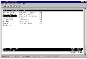
YSTEMU
TILITYUse the SYSTEM UTILITY menu to view and set the system parameters shown in Figure 4.
Figure 3. System Utility Menu
S
YSTEMU
TILITY> U
PGRADEF
IRMWARESelect the firmware upgrade method and perform upgrade from this menu.
S
YSTEMU
TILITY> U
PGRADEF
IRMWARE> T
RANSFERM
ETHODThe customer can update firmware when unit enhancements are released.
The two methods for upgrading are XMODEM and TFTP. (See the DLP section of this manual for more information.) TFTP requires a TFTP server running on the network. The unit starts a TFTP client function which gets the upgrade code from the TFTP server. Selecting XMODEM will load the upgrade code through the CRAFT port using any PC terminal emulator with XMODEM capability. The factory default is
TFTP.
S
YSTEMU
TILITY> U
PGRADEF
IRMWARE> TFTP S
ERVERA
DDRESSS
YSTEMU
TILITY> U
PGRADEF
IRMWARE> TFTP S
ERVERF
ILENAMEThis is required when the transfer method is TFTP. It is the case-sensitive file name which contains the upgrade code. The factory default is no entry in the TFTP SERVER FILENAME field.
S
YSTEMU
TILITY> U
PGRADEF
IRMWARE> T
RANSFERS
TATUSThis appears when TFTP is used. It displays the status of the transfer as it happens. Any error or success message will be displayed here.
S
YSTEMU
TILITY> U
PGRADEF
IRMWARE> S
TARTT
RANSFERThis activator is used when the configurable items in this menu are complete. This will initiate the transfer for either TFTP or XMODEM upgrades.
S
YSTEMU
TILITY> U
PGRADEF
IRMWARE> A
BORTT
RANSFERUse this activator to cancel any TFTP transfer in progress.
S
YSTEMU
TILITY> C
ONFIGT
RANSFERSelect the config transfer method and perform the transfer from this menu.
S
YSTEMU
TILITY> C
ONFIGT
RANSFER> T
RANSFERM
ETHODSends a file containing the unit configuration to a PC connected to the CRAFT port using XMODEM protocol or to a file on a TFTP server using the TFTP protocol.
CONFIG TRANSFER also lets you save the unit configuration as a backup file, so you can use the same configuration with multiple units. In addition, CONFIG TRANSFER can retrieve a configuration file from a TFTP server.
To support these transfers, ADTRAN delivers a TFTP program with the unit called TFTP Server. You can configure any PC running Microsoft Windows with this software, and store a configuration file.
Only one configuration transfer session (upload or download) can be active at a time. XMODEM and TFTP
are supported.
Before using START TRANSFER, the unit should have a valid IP address, subnet mask, and
default gateway (if required). See DLP-2, Setting IP Parameters for the Total Access 544R for more information.
S
YSTEMU
TILITY> C
ONFIGT
RANSFER> TFTP S
ERVERIP A
DDRESSSpecifies the IP address of the TFTP server. Get this number from your system administrator. If using the ADTRAN Utilities TFTP server, this number appears in the TFTP server status window. The factory default value is 0.0.0.0.
S
YSTEMU
TILITY> C
ONFIGT
RANSFER> TFTP S
ERVERF
ILENAMEDefines the name of the configuration file that you transfer to or retrieve from the TFTP server. The default name is ta_iad.cfg, but you can edit this name.
S
YSTEMU
TILITY> C
ONFIGT
RANSFER> C
URRENTT
RANSFERS
TATUSIndicates the current status of the update.
S
YSTEMU
TILITY> C
ONFIGT
RANSFER> P
REVIOUST
RANSFERS
TATUSIndicates the status of the previous update.
S
YSTEMU
TILITY> C
ONFIGT
RANSFER> L
OADA
NDU
SEC
ONFIGRetrieves the configuration file specified in the TFTP Server Filename field from the server. To start this command, enter Y to begin or enter N to cancel.
S
YSTEMU
TILITY> C
ONFIGT
RANSFER> S
AVEC
ONFIGR
EMOTELYSaves the configuration file specified in TFTP Server Filename to the server identified in TFTP Server IP Address. To start this command, enter Y to begin or enter N to cancel.
S
YSTEMU
TILITY> S
YSTEMU
TILIZATIONView the CPU utilization stats from this menu.
S
YSTEMU
TILITY> S
YSTEMU
TILIZATION> P
ERFORMANCEClear the system utilization stats and view the total and current CPU utilization stats from this menu.
If you execute this command, the unit retrieves the configuration file, reboots, then restarts using the new configuration
S
YSTEMU
TILITY> S
YSTEMU
TILIZATION> P
ERFORMANCE> T
OTALA
VGCPU U
TILIZATION TOTAL AVG CPU UTILIZATION is a running total of CPU utilization since the last reset.S
YSTEMU
TILITY> S
YSTEMU
TILIZATION> P
ERFORMANCE> C
URRENTA
VGCPU U
TILIZATION CURRENT AVG CPU UTILIZATION is the running total of CPU utilization since the last clear.S
YSTEMU
TILITY> S
YSTEMU
TILIZATION> P
ERFORMANCE>T
OTALA
VGISR U
TILIZATIONThe Total Avg ISR Utilization is a running total average of the ISR Utilization.
S
YSTEMU
TILITY> S
YSTEMU
TILIZATION> P
ERFORMANCE> C
LEARS
TATSThis activator will clear all the system utilization performance stats.
S
YSTEMU
TILITY> P
INGActivate the ping test and define the ping packet characteristics from this menu.
S
YSTEMU
TILITY> P
ING> S
TART/S
TOPActivator to start and cancel a ping test.
S
YSTEMU
TILITY> P
ING> H
OSTA
DDRESSIP address or domain name (if DNS is configured) of device to receive the ping. This field is left blank by default.
S
YSTEMU
TILITY> P
ING> S
IZE(40-1500)
Total size of the ping to send. Range is 40 to 1500 bytes. The default is 64.
S
YSTEMU
TILITY> P
ING> #
OFP
ACKETSOnly one ping session can be active at a time.
S
YSTEMU
TILITY> P
ING> # T
RANSMITSTotal packets sent (read only).
S
YSTEMU
TILITY> P
ING> # R
ECEIVESTotal packets received (read only).
S
YSTEMU
TILITY> P
ING> % L
OSSPercentage loss based on ping returned from host (read only).
S
YSTEMU
TILITY> T
RACEROUTEUtility program used to trace a data path to a final destination.
S
YSTEMU
TILITY> T
RACEROUTE> T
RACET
ARGETSpecifies the IP address of the remote system to trace the routes to.
S
YSTEMU
TILITY> T
RACEROUTE> M
AXIMUMH
OPSSpecifies the maximum number of router exchanges allowed when traveling to the final destination (specified using the TRACE TARGET field) Range is 1 to 30. Default is 30.
S
YSTEMU
TILITY> T
RACEROUTE> T
IMEOUT(
IN SECS)
Specifies the maximum delay (in milliseconds) given to a host (along a path to the final destination) to respond to the probe datagram sent before considering the packet a failure.
S
YSTEMU
TILITY> T
RACEROUTE> R
ETRIESSpecifies the number of times the probe datagram is sent to each host (along the path to the final destination).
S
YSTEMU
TILITY> T
RACEROUTE> B
EGINT
RACEROUTEActivates the traceroute process by sending a probe datagram with a Time To Live (TTL) value of 1.
S
YSTEMU
TILITY> R
ESETU
NITS
YSTEMU
TILITY> T
ERMINALM
ODESelecting the terminal mode gives the user a command-line prompt to perform utilities such as pings, traceroutes, resets, firmware updates, configuration, and more. TERMINAL MODE can also be accessed by using the shortcut keys CNTRL T from other menu screens. From this command-line prompt, you can: • Perform a reset with the command "reset"
• Perform a factory restore with the command "factory_reset"
• Configure the unit. The unit has the ability to download a text file which contains the configuration of the entire unit. This configuration may then be altered in a text editor, and then uploaded to a unit. • Debug and troubleshoot. This function would be carried out with the assistance of ADTRAN Technical
Support.
• Start and stop the fail-safe timer for the auto-config feature. • Perform a firmware upgrade via TFTP.
upgrade_firmware hostname filename
• Use the save command to write the entire configuration to flash. • Display the unit’s MAC address with the command mac
• Perform a ping or extended ping. Syntax is:
ping hostname/address [repeat xx] [size xx] [timeout xx] [source xx] [noNat]
Options:
repeat <repeat count> Number of pings to send (default 5)
size (datagram size) Range is 40-1500
timeout (seconds) Timeout in seconds (range 1-10)
source (address or name) Source address or interface name to use
noNat Do not NAT the ping packet
Options may be entered in any order and may be truncated. Valid interface names are eth0, fdl0, ppp0, fr0, fr1, etc. Example usage: ping 10.0.0.5 r si 1500 so eth0 n
This will ping with a repeat count of 10. The datagram size is 1500 bytes, and the source address used in the ping packet will be the ethernet IP address. The “noNat” option has been specified, so if NAT is enabled, this packet will NOT be translated.
• Perform a traceroute or extended traceroute. Syntax is: