AT&T System 75
and System 75 XE
Implementation
Release 1 Version 3
Write: AT&T Customer Information Center 2855 North Franklin Road
P.O. Box 19901
Indianapolis, Indiana 46219-1385
While reasonable efforts were made to ensure that the information in this document was complete and accurate at the time of printing, AT&T can assume no responsibility for errors. Changes or
corrections to the information in this document may be incorporated into future reissues.
Published by
The AT&T Documentation Management Organization
Contents
C H A P T E R 1 . I N T R O D U C T I O N O v e r v i e w
O r g a n i z a t i o n How to Use
C H A P T E R 2 . A R S A N D T R U N K S — I N S T R U C T I O N S A N D F O R M S Overview
Automatic Route Selection T r u n k s
C H A P T E R 3 . O P T I O N A L F E A T U R E S
C H A P T E R 4 . C O M M U N I C A T I O N S S U R V E Y Overview
Survey Steps
C H A P T E R 5 . S Y S T E M F E A T U R E S , F U N C T I O N S , A N D S E R V I C E S Overview
AAR/ARS Partitioning Abandoned Call Search A b b r e v i a t e d D i a l i n g A c c e s s T r u n k G r o u p
Advanced Private Line Termination (APLT) Trunk Group A g e n t C a l l H a n d l i n g
Applications Processor (AP) Interface and Assignments (V3) AP Demand Print (V3)
Attendant Console
Attendant Control of Trunk Group Access
Attendant Direct Extension Selection With Busy Lamp Field Attendant Direct Trunk Group Selection
Attendant Display
Automatic Route Selection Automatic Wakeup
Bridged Call Appearance— Multi-Appearance Voice Terminal Business Communications/Personal Terminals
Busy Verification of Terminals and Trunks Call Coverage
Call Forwarding—All Calls
Call Management System (CMS) Interface and Assignments Call Park
Call Pickup
Call Waiting Termination Central Office Trunk Group Centralized Attendant Service Class of Restriction
Class of Service Code Calling Access Consult
Coverage Callback
Coverage Incoming Call Identification
Customer Provided Equipment (CPE) Trunk Group Data Call Setup
Data Hot line Data Modules
Data-Only Off-Premises Extensions Data Privacy
Data Restriction Dial Plan
Digital Multiplexed Interface (DMI) Trunk Group
Direct Department Calling and Uniform Call Distribution Direct Inward Dialing
Direct Outward Dialing
Distinctive Ringing (Alerting)
Distributed Communications System (DCS) DCS Alphanumeric Display for Terminals
DCS Attendant Control of Trunk Group Access DCS Attendant Direct Trunk Group Selection DCS Attendant Display
DCS Automatic Callback
DCS Automatic Circuit Assurance
DCS Busy Verification of Terminals and Trunks DCS Call Forwarding-All Calls
DCS Leave Word Calling
DCS Trunk Group Busy/Warning Indication D o N o t D i s t u r b
DS1 Tie Trunk Service EIA lnterface
Emergency Access to the Attendant Facility Busy Indication
Facility Restriction Levels and Traveling Class Marks Facility Test Calls
Forced Entry of Account Codes Foreign Exchange (FX) Trunk Group G o T o C o v e r
H o l d
Hot Line Service Hunting
Individual Attendant Access
Intraflow and lnterflow Last Number Dialed Leave Word Calling
Loudspeaker Paging Access Manual Message Waiting
Manual Originating Line Service Manual Signaling
“MEGACOM”, “MEGACOM” 800, or “MEGACOM” 800 DNIS Services Modem Pooling
Multi-Appearance Preelection and Preference Multiple Listed Directory Numbers
Music-on-Hold Access Network Access-Private Network Access-Public Night Service—Hunt Group
Night Service-Night Console Service Night Service-Night Station Service
Night Service-Trunk Answer From Any Station Night Service-Trunk Group
Off-Premises Station
Permanent Switched Calls
Personal Central Office Line (PCOL) Personalized Ringing
Priority Calling
Privacy— Attendant Lockout Privacy— Manual Exclusion
Property Management System Interface Queue Status Indications
Recorded Announcements
Recorded Telephone Dictation Access Release Link Trunk Group
Remote Access Remote Administration Restriction—Controlled Restriction—Miscellaneous Terminal Restriction—Miscellaneous Trunk Restriction—Toll/Code Restriction—Voice Terminal—Inward
Restriction—Voice Terminal—Manual Terminating Line Restriction—Voice Terminal—Origination
Restriction—Voice Terminal—Outward Restriction—Voice Terminal—Termination Ringback Queuing
Send All Calls Service Observing
Single-Digit Dialing and Mixed Station Numbering SMDR Account Code Dialing
Station Message Detail Recording (SMDR) Subnet Trunking
Tandem Trunk Group
Terminating Extension Group Tie Trunk Group
Timed Reminder
Trunk Group Busy/Warning Indicators To Attendant Trunk Identification by Attendant
Trunk Groups
Trunk-to-Trunk Transfer Uniform Call Distribution Uniform Dial Plan
Voice Message Retrieval
500 Voice Terminal 510D Personal Terminal
515 Business Communications Terminal (BCT) 2500 Voice Terminal
7101A Voice Terminal 7103A Voice Terminal 7303S Voice Terminal 7305S Voice Terminal 7309H Voice Terminal 7401D Voice Terminal 7403D Voice Terminal 7404D Voice Terminal 7405D Voice Terminal 7406D Voice Terminal 7407D Voice Terminal
Personal Computer (PC) 6300 & 7300/Private Branch Exchange (PBX) Connection
CHAPTER 6. SYSTEM FORMS Overview
Abbreviated Dialing—Enhanced List Abbreviated Dialing—Group List Abbreviated Dialing—Personal List Abbreviated Dialing—System List Abbreviated Dialing—7103A List Allowed Calls List
Attendant Console Authorization Codes
Call Coverage Answer Group
Call Coverage Module Call Coverage Paths Class of Restriction Class of Service Console Parameters Data Line Data Module Dial Plan
Digit Absorption Display Module DS1 Circuit Pack Feature Access Codes Feature Module
Feature Related System Parameters H o p C h a n n e l A s s i g n m e n t s Hospitality-Related System Parameters Hunt Groups
Intercom Groups Interface Data Module Interface Links
Listed Directory Numbers
Inter-Exchange Carrier (IXC) Codes
Loudspeaker Paging and Code Calling Access Modem Pool Group
Modular Processor Data Modules/Modular Trunk Data Modules Netcon Data Module
Permanent Switched Calls Pickup Groups
Processor Channel Assignment Recorded Announcements
30 Multi-Button Electronic (MET) Voice Terminal 500 Voice Terminal
510D Personal Terminal
515 Business Communications Terminal 2500 Voice Terminal
7101A Voice Terminal 7103A Voice Terminal 7303S Voice Terminal 7305S Voice Terminal 7309H Voice Terminal
6-204 6-216 6-221 6-236 6-250 6-255 6-260 6-265 6-277 6-290 7401D Voice Terminal
7403D Voice Terminal 6-312
7404D Voice Terminal 6-325
7405D Voice Terminal 6-341
7406D Voice Terminal 6-357
7407D Voice Terminal 6-373
Personal Computer (PC)/Private Branch Exchange (PBX) Connection 6-390
6-302
C H A P T E R 7 . Abbreviated Abbreviated Abbreviated Abbreviated Abbreviated Abbreviated Abbreviated Abbreviated Abbreviated Abbreviated BLANK FORMS Dialing—Enhanced Dialing—Enhanced Dialing— Enhanced Dialing—Enhanced Dialing— Enhanced Dialing —Enhanced Dialing—Enhanced Dialing—Enhanced Dialing— Enhanced Dialing— Enhanced
List Form 0 List Form l List Form 2 List Form 3 List Form 4 List Form 5 List Form 6 List Form 7 List Form 8 List Form 9
Abbreviated Dialing—Group List Abbreviated Dialing—Personal List Abbreviated Dialing—System List Abbreviated Dialing—7103A List Access Trunk Group
Allowed Calls List A P L T
Attendant Console Authorization Codes
Automatic Route Selection—Foreign Numbering Plan Area (FNPA) Automatic Route Selection—Home Numbering Plan Area (HNPA)
Automatic Route Selection—Remote Home Numbering Plan Area (RHNPA) Automatic Route Selection—Toll Table
Call Coverage Answer Group Call Coverage Module Call Coverage Paths Central Office Trunk Group Class of Restriction Class of Service
Code Restriction FNPA Code Restriction HNPA Console Parameters CPE Trunk Group Data Line Data Module Dial Plan
Digit Absorption Display Module
Direct Inward Dialing Trunk Group
Digital Multiplexed Interface (DMI) Trunk Group DS1 Circuit Pack
Hunt Groups Intercom Groups Interface Data Module Interface Links
Inter-Exchange Carrier (lXC) Codes Listed Directory Numbers
Loudspeaker Paging and Code Calling Access Modem Pool Group
Modular Processor Data Modules/Modular Trunk Data Modules Netcon Data Module
Permanent Switched Calls
Personal Central Office Line Groups (PCOLGS) Pickup Groups
Processor Channel Assignment Recorded Announcements
Recorded Announcement Data Module Release Link Trunk Group
Remote Access
RNX Translation Table Routing Patterns Synchronization Plan Tandem Trunk Group
Terminating Extension Group Tie Trunk Group
Wide Area Telecommunications Service Trunk Group 10 Multi-Button Electronic (MET) Voice Terminal 20 Multi-Button Electronic (MET) Voice Terminal 30 Multi-Button Electronic (MET) Voice Terminal
500 Voice Terminal 5100 Personal Terminal
515 Business Communications Terminal 2500 Voice Terminal
7101A Voice Terminal 7103A Voice Terminal 7303S Voice Terminal 7305S Voice Terminal 7309H Voice Terminal 7401D Voice Terminal 7403D Voice Terminal 7404D Voice Terminal 7405D Voice Terminal 7406D Voice Terminal 7407D Voice Terminal
Personal Computer (PC)/Private Branch Exchange (PBX) Connection
CHAPTER 8. REFERENCES
CHAPTER 9. INDEX
7-156 7-157 7-161 7-163 7-164 7-165 7-166 7-167 7-169 7-170 7-171 7-173 7-176 7-179 7-182 7-186
8-1
Figure 4-2. Figure 4-3. Figure 4-4. Figure 4-5. Figure 4-6. Figure 4-7. Figure 4-8. Figure 4-9. Figure 5-1. Figure 5-2. Figure 5-3. Figure 5-4. Figure 5-5. Figure 5-6. Figure 5-7. Figure 5-8. Figure 5-9. Figure 5-10. Figure 5-11.
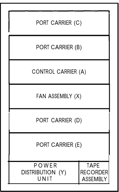
Model 3 Carrier Locations and Designations (Front View) (V3) Models 1 and 2 Carrier Locations and Designations (Front View) (V3)
Port Assignment Record (For up to Eight Ports) Port Assignment Record (For up to 24 Ports)
Control Cabinet and Port Cabinet Circuit Pack Slot Location— Four Cabinet System (Front View) (System 75 XE)
4-21
4-22 4-23 4-24
4-25 Cabinet Locations and Designations—Four Cabinet System (Front
View) (System 75 XE)
Circuit Pack Administration Form (V3)
Circuit Pack Administration Form (System 75 XE)
Applications Processor Connected to a Digital Line Circuit Pack System 75 V3 AUDIX Connections and Assignments
System 75 XEV3 AUDIX Connections and Assignments Located on Back of Control Carrier
AUDIX Used in a Distributed Communications System Example of Interface Data Module Forms Used to Assign AUDIX Interface Links
Example of Interface Links Form Used To Assign and Enable Interface Link 4 for a Small or Medium AUDIX—Used With MPDM (Data Module) Ext. 49005
Example of Interface Links Form Used To Assign and Enable Interface Link 4 for a Large AUDIX—Used With MTDM (Data Module) Ext. 49006
Example of interface Links Form Used To Assign and Enable Interface Link 1 for AUDIX (XEV3 Only)—Used When Audix Is Connected to the PIB Jack on the Control Carrier
Example of Data Module Form Used To Assign a Modular
Processor Data Module To a Small or Medium AUDIX Example of Data Module Form Used To Assign a Modular Trunk Data Module To a Large AUDIX
Example of Processor Channel Assignment Form Used To Assign Processor Channel 59 To AUDIX Using Link 4 (V3)
Figure 5-12. Figure 5-13. Figure 5-14. Figure 5-15. Figure 5-16. Figure 5-17. Figure 5-18. Figure 5-19. Figure 5-20. Figure 5-21. Figure 5-22. Figure 5-23. 5-53 Figure 5-24. Figure 5-25. Figure 5-26. Figure 5-27. Figure 5-28. 5-108 Figure 5-29. Figure 5-30. Figure 5-31. Figure 5-32.
Example of 2500-Type Voice Terminal Form Assigned to AUDIX
Voice Port 5-38
Example of 2500-Type Voice Terminal Form Assigned to AUDIX
Voice Port 5 - 3 8
Example of 2500-Type Voice Terminal Form Assigned to AUDIX
Voice Port 5-39
Example of 2500-Type Voice Terminal Form Assigned to AUDIX
Voice Port 5-40
Example of Hunt Group Form Used To Assign AUDIX Hunt Group
and Associated Voice Ports 5-40
Example of Call Coverage Path Form Used To Assign AUDIX
Hunt Group Extension Number 48123 To Coverage Point 3 5-41 Example of Feature Access Code Form Used To Assign Access
Code 111 To Transfer Into AUDIX Feature 5-41 Recorded Announcement Form Used To Assign an AUDIX
Announcement on the TN750 Announcement Circuit Pack 5-42 System 75 Remote Switch 2 AUDIX Hunt Group Assignments 5-42 System 75 Remote Switch 3 AUDIX Hunt Group Assignments 5-42 Typical ACD Arrangement
Typical CAS Main and Branch Console Parameters and RLT
Forms 5-82
Example of Data Module Connections
Distributed Communications System Using DS1 Facilities 5-122
Dial Platform 5-123
RNX Translation Form 5-125
DCS Voice Tie Trunk Group Number 27 Assignments From
Switch A to Switch B 5-126
DCS Voice Tie Trunk Group Number 48 Assignments From
Switch A to Switch C 5-128
DCS AVD DS1 Signaling Trunk Group Number 28 Assignments
From Switch A to Switch B 5-130
DCS DS1 AVD signaling Trunk Group Number 49 Assignments
From Switch A to Switch C 5-132
Routing Pattern for Trunk Group Number 27 From Switch A to
Figure 5-36. Interface Data Module Form Used to Assign Interface Links 1 and
3 From Switch A To Switches B and C 5-138
Figure 5-37. Interface Links Form Used To Assign DCS Links From Switch A
T o S w i t c h e s B a n d C 5-139
5-140 5-171 Figure 5-38.
Figure 5-39. Figure 5-40.
Processor Channel Assignments for Interface Links 1 and 3 ISN Connection Using TN726 Data Line Circuit Pack Example of Integrated and Combined Modem Pooling
Connections 5-190 5-244 5-245 Figure 5-41. Figure 5-42. Figure 5-43.
Typical SMDR Output Device Connections
S M D R C o n n e c t e d t o A p p l i c a t i o n s P r o c e s s o r PC/PBX Connections Using a 7403D, 7404D, or 7405D Voice
Terminals 5-280
Figure 6-1. Attendant Console Button Assignments—Including Alphanumeric
Display 6-20
Figure 6-2. Optional Selector Console Administrable Hundreds Group Select
Buttons-Attendant Console Form 6-21
Figure 6-3. Attendant Console 24 Administrable Feature Button Number
Assignments—Attendant Console Form 6-28
Figure 6-4. Model 7405D Voice Terminal With Optional Call Coverage Module
and Administrable Button Assignments 6-42
6-47 6-49 6-58 6-75 Figure 6-5. Figure 6-6. Figure 6-7. Figure 6-8. Figure 6-9.
Example of Four Call Coverage Paths and Associated Linkage Example of a Typical Call Coverage Path Assignment Example of DLC Applications
How To Assign Hotel/Motel Features To Voice Terminal Model 7405D Voice Terminal With Optional Digital Display Module
and Administrable Button Assignments 6-85
Figure 6-10. Model 7405D Voice Terminal With Optional Feature Module and
Administrable Button Assignment 6-104
6-191 6-203 6-215 Figure 6-11. Figure 6-12. Figure 6-13.
Figure 6-14. Figure 6-15. Figure 6-16. Figure 6-17. Figure 6-18. Figure 6-19. Figure 6-20. Figure 6-21. Figure 6-22. Figure 6-23. Figure 6-24. Figure 6-25. Figure 6-26. Figure 6-27. Figure 6-28. Table 2-A. Table 4-A. Table 4-B. Table 4-C. Table 4-D. Table 4-E. Table 4-F. Table 5-A. Table 6-A. Table 6-B. Table 6-C. Table 6-D.
500 Voice Terminal
510D Personal Terminal Administrable Screen Button Assignments
515 Business Communications Terminal (BCT) 2500 Voice Terminal
7101A Voice Terminal 7103A Voice Terminal 7303S Voice Terminal 7305S Voice Terminal 7309H Voice Terminal 7401D Voice Terminal 7403D Voice Terminal 7404D Voice Terminal 7405D Voice Terminal 7406D Voice Terminal 7407D Voice Terminal
Tables
6-220 6-235 6-249 6-254 6-259 6-264 6-276 6-289 6-301 6-311 6-324 6-340 6-356 6-372 6-389ARS Routing Table 2-3
System 75 Port Circuit Packs and Associated Carrier Locations 4-4
System 75 Carrier Loading Order 4 - 5
System 75 Port Circuit Pack Loading Order in Carriers 4-6 System 75 XE Port Circuit Packs and Associated Cabinet
Locations 4 - 9
System 75 XE Cabinet Loading Order 4 - 1 0
System 75 XE Port Circuit Pack Loading Order in Carriers 4 - 1 1
ARS Routing Table 5 - 6 2
Attendant Console 24-Button Assignment 6 - 2 2
Attendant Console—ACD Button Assignments 6 - 2 5
Attendant Console—Hospitality Button Assignments 6 - 2 7
Button or Feature Selection for Attendant Display Module Buttons
Table 6-H. Table 6-I. Table 6-J. Table 6-K. Table 6-L. Table 6-M. Table 6-N. Table 6-O. Table 6-P. Table 6-Q. Table 6-R. Table 6-S. Table 6-T. Table 6-U. Table 6-V. Table 6-W. Table 6-X. Table 6-Y. Table 6-Z. Table 6-AA. Table 6-AB. Table 6-AC.
DLDM Form Option Settings for Connection to Data Terminal or Personal Computer
DLDM Form Option Settings for Terminating Connection to Host Computer
DLDM Form Option Settings for Originating Connection from a Host Computer
DLDM Form Option Settings for Outgoing Line to ISN DLDM Form Option Settings for Incoming Line from ISN Display Module Button Assignments
Feature Module Button Assignments
Voice Terminal Button Assignments for 10 MET Voice Terminal Button Assignments for 20 MET Voice Terminal Button Assignments for 30 MET Voice Terminal Button Assignments for 510D Voice Terminal Button Assignments for 515 BCT Voice Terminal Button Assignments for 7303S Voice Terminal Button Assignments for 7305S Voice Terminal Button Assignments for 7309H Voice Terminal Button Assignments for 7401D Voice Terminal Button Assignments for 7403D Voice Terminal Button Assignments for 7404D Voice Terminal Button Assignments for 7405D Voice Terminal Button Assignments for 7406D Voice Terminal Button Assignments for 7407D
Voice Terminal Button Assignments for Personal Computer
CHAPTER 1. INTRODUCTION
CHAPTER 1. INTRODUCTION
Overview
This manual provides the procedures and associated forms for collecting system and voice terminal features. This information is used with AT&T System 75—Administration, 555-200-500, to initialize the AT&T System 75 and System 75 XE using the System Access Terminal.
In the planning process, system requirements were identified by the AT&T Account Team and the customer. Those requirements were converted into orderable system hardware when the Account Team configured the system.
This manual is solely concerned with AT&T System 75 implementation; that is, the completion of paper records and forms that are used to initialize and administer the System 75 Release 1 Version 3 or the System 75 XE.
This manual explains the forms required to implement the various system and voice terminal features. Instructions on how to complete each paper record and form are also provided.
AT&T System 75—Administration, 555-200-500, explains how to use the paper records to
initialize and administer the system.
The chart in Figure 1-1 depicts work activities and relative time frames.
This manual provides the forms and instructions required to implement a System 75 Release 1 Version 3 (RlV3) or a System 75 XE. All forms and features described in this manual apply to a Release 1 Version 3 System 75 and a System 75 XE unless otherwise noted as V3 or System 75 XE.
This manual is being reissued to include the following information.
• Add V3 enhancements
Ž Add information for the Hospitality Parameter Reduction feature
• Add 7309H voice terminal
• Provide detailed information on how to implement AUDIX in a DCS or non-DCS environment.
To complete this manual, you must:
• Have hardware and feature knowledge (consult AT&T System 75—System
Description, 555-200-200, and AT&T System 75—Feature Description, 555-200-201 )
Organization
The other chapters in this manual are:
Chapter 2—ARS and Trunks— Instructions and Forms—Lists the forms required to implement Automatic Route Selection and System 75 trunks.
Chapter 3—Optional Features— Lists the optional features available to System 75 users. These features are not part of the standard system capabilities and must be purchased separately.
Chapter 4—Communications Survey—Describes the Communications Survey. This information is essential to get started with system implementation.
Chapter 5—System Features, Functions, and Services— Provides the instructions required to implement the system and voice terminal features. Included in each feature description is a table listing the feature forms required to implement that feature and the page numbers where they can be found. The blank form page number is also provided.
Chapter 6—System Forms—Contains the feature forms and instructions for completing each field on the forms. The forms in this part provide an accurate representation of the screen forms that are displayed on the System Access Terminal (SAT) during system initialization and on-going administration.
Chapter 7—Blank Forms—Contains a complete set of blank forms. Reproduce these forms as needed to implement the system.
Chapter 8—References— Provides a list of System 75 reference documentation. A brief description of each document is included.
Chapter 9—Index—Contains a permuted index.
The information in Chapters 2, 5, and 6 of this manual is valid for adding and changing features after the system has been initialized. This manual is the only source of a detailed description of the screen forms and a list of the forms that can be completed for a given feature.
To use this manual after initialization, the following items should be followed:
1. Certain identifiers, such as hunt group number, may be part of the administrative command instead of an assignable field. For example, assume hunt group 4 is established (on form for Hunt Group 4) during implementation. The “4” is entered on the form to identify the hunt group. However, when the system is initialized, the command add hunt-group 4 is used to access the appropriate screen form for adding Hunt Group 4. The “4” is already stored in translation for that hunt group. Similarly, the change hunt-group 4 command is used to make changes on hunt group 4. A complete list of administrative commands is given in AT&T System 75—
CHAPTER 1. INTRODUCTION
2. Some of the forms listed in Chapter 5 should not be changed frequently. Specifically, the Dial Plan Record, Feature Related System Parameters, and Feature Access Codes forms normally do not require changes after initialization. When making additions or changes to the system, verify the required forms and/or fields have been completed. Specify the additional data needed to add or change the desired feature.
Many of the forms that appear on the SAT contain dynamic fields. Dynamic fields appear or disappear on the form depending on how another field is assigned. Dynamic fields are identified by implementation notes below the form.
How to Use
The procedural checklist in the following steps should be followed to complete the forms in this manual.
1. Become familiar with the contents of this manual.
2. Conduct a Communications Survey. Instructions for completing a Communications Survey are in Chapter 4.
3. Using Chapter 5 of this manual as a guide for implementing the desired features available to System 75 users, complete the forms as shown in Chapters 2 and 6. Blank forms are in Chapter 7. After these forms have been completed, they should be used with AT&T System 75—Administration, 555-200-500, to initialize the system.
CHAPTER 2. ARS AND TRUNKS—INSTRUCTIONS AND FORMS
CHAPTER 2. ARS AND TRUNKS—INSTRUCTIONS
AND FORMS
Overview
This chapter contains the forms and instructions required to assign Automatic Route Selection (ARS) and System 75 trunks.
The first part of this chapter covers ARS. The second part covers the System 75 trunks. The blank forms for ARS and trunks are in Chapter 7. Reproduce a blank form for the ARS and trunk forms being used.
Automatic Route Selection
ARS routes calls over the public network based on the preferred (normally the least expensive) route available at the time the call is placed. ARS provides a choice of up to six routes from any given public network call. The following types of trunk groups can be accessed by ARS:
• Local central office—Used for local calls and to provide access to long-distance carrier. Access to the long-distance carrier can be provided automatically by the central office or by a carrier access code.
• Foreign exchange—Used to emulate local calling in an area served by the local central office.
• Wide Area Telecommunications Service (WATS)—Used to provide calling to predefine geographic areas at a rate based on expected usage.
• Tie trunks—Used to provide access to an Electronic Tandem Network (ETN), or to an Enhanced Private Switched Communications Service (EPSCS) or Common Control Switching Arrangement (CCSA) office.
The following forms are used to assign ARS features:
Ž ARS Foreign Numbering Plan Area (FNPA) • ARS Home Numbering Plan Area (HNPA)
Ž ARS Remote Home Numbering Plan Area (RHNPA) • ARS Toll Table
Ž Code Restriction HNPA
• Dial Plan
• Feature Access Codes
• RNX Translation Table
ARS—Foreign Numbering Plan Area (FNPA)
Automatic Route Selection—Foreign Numbering Plan Area (FNPA)
Purpose
This form is used to assign the routing pattern associated with each FNPA. The ARS FNPA table points to the appropriate Routing Pattern for each nonlocal NPA or points to a 6-digit translator so the call will be routed on both the NPA and the office code.
Although they are not FNPAs, the codes 00x, 01x, 10x, and 11x (where x is a number 0 through 9) can be assigned for routing calls beginning with these digits.
The system recognizes certain types of dialing patterns on outgoing calls and routes these calls via special entries in the FNPA or HNPA table. Table 2-A lists the special dialing patterns along with the associated FNPA or HNPA table entry through which that type of call is routed.
Table 2-A. ARS Routing Table
CALL TYPE OPERATOR INTERNATIONAL-DIRECT DIAL INTERNATIONAL-OPERATOR ASSIST OPERATOR ASSIST
LONG DISTANCE SERVICE LONG DISTANCE IN NPA LONG DISTANCE-TOLL FREE
LONG DISTANCE-DIRECTORY ASSIST LONG DISTANCE IN HOME NPA LONG DISTANCE OUT SIDE OF NPA LDC-ACCESS CODE
LDC-OPERATOR
LDC-INTERNATIONAL DIRECT DIAL LDC-INTERNATIONAL-OPERATOR ASSIST LDC-OPERATOR ASSIST
LDC-DIRECTORY ASSISTANCE LDC-LOCAL TOLL CALL
LDC-TOLL FREE LONG DISTANCE LDC-TOLL CALL WITHIN HOME NPA LDC-LONG DISTANCE DIRECTORY ASSIST LDC-LONG DISTANCE OUTSIDE OF NPA
Legend: N I X ( ) ROUTES ON O11X...X O1X...X OX...X (1)N11 (1 )NXX-XXXX (1)800-NXX-XXXX (1 )NIX-555-XXXX (1)HNPA-NXX-XXXX (1)NIX-NXX-XXXX 10XXX 10XXX-0 10XXX-011X...X 10XXX-01X...X 10XXX-0X...X 10XXX (1 )555-XXXX 10XXX (1 )NXX-XXXX 10XXX(1)800-NXX-XXXX 10XXX (1 )HNPA-NXX-XXXX 10XXX (1)NIX-555-XXXX 011 010 001 N11 NXX 800 005 NXX NIX 100 100 111 110 101 555 NXX 800 NXX 005 10XXX(1)NIX-NXX-XXXX NIX — any digit 2-9
— digit 0-1 — any digit 0-9 — an optional digit LDC — Long Distance Carrier
TRANSLATOR TABLE FNPA FNPA FNPA FNPA FNPA HNPA FNPA FNPA HNPA FNPA FNPA FNPA FNPA FNPA FNPA HNPA HNPA FNPA HNPA FNPA FNPA
Typical assignments for the FNPA Table are as follows: — "H" —pattern/table assignment for the HNPA
— "R"(1-32)—office code translation of a given NPA and Pattern Numbers
Patterns should be created to accommodate individual customer needs. Careful application of this table permits Automatic Route Selection for all types of calling including IDDD (International Direct Distance Dialing) and carriers other than AT&T.
Instructions
Make assignments as required for the following fields:
• Partitioned Group Number—Enter a group number from 1 through 4.
ARS—Foreign Numbering Plan Area (FNPA)
Page 1 of 1 A R S F N P A T A B L E
P a r t i t i o n e d G r o u p N u m b e r : 1 P a t t e r n C h o i c e A s s i g n m e n t
000-019 100-119 200-219 300-319 400-419
Page 1 of 1 A R S F N P A T A B L E
P a r t i t i o n e d G r o u p N u m b e r : 1 P a t t e r n C h o i c e A s s i g n m e n t s
5 0 0 - 5 1 9 6 0 0 - 6 1 9 7 0 0 - 7 1 9 8 0 0 - 8 1 9 9 0 0 - 9 1 9 0 0 : 2 10:2 00:2 10:2 0 0 : 2 10:2 00:2 10:2 00:2 10:2 01:2 11:2 0 1 : 2 11:2 0 1 : 2 11:2 0 1 : 2 11:2 01:2 11:2 02:2 12:2 02:2 12:2 0 2 : 2 12:2 02:2 12:2 02:2 12:2 0 3 : 2 13:2 0 3 : 2 13:2 03:2 13:2 03:2 13:2 03:2 13:2 0 4 : 2 14:2 04:2 14:2 0 4 : 2 14:2 0 4 : 2 14:2 04:2 14:2 0 5 : 2 15:2 0 5 : 2 15:2 0 5 : 2 15:2 05:2 15:2 05:2 15:2 0 6 : 2 16:2 0 6 : 2 16:2 06:2 16:2 0 6 : 2 16:2 06:2
07:2 17:2 07:2 17:2 07:2 1 7 : 2 07:2 17:2 07:2 08:2 18:2 08:2 18:2 08:2 18:2 08:2 18:2 08:2
ARS—Home Numbering Plan Area (HNPA)
Automatic Route Selection—Home Numbering Plan Area (HNPA)
Purpose
This form is used to assign the routing pattern associated with each of the 800 office codes in the local area code. The ARS HNPA Table points to the appropriate routing pattern for each office code within the home NPA.
The default value for all 800 office codes is pattern 1. Normally, pattern 1 should be used as the HNPA toll pattern because in most NPAs there are more toll offices than local office codes. This will minimize the number of changes required to complete the form.
Instructions
Make assignments, as required, for the following fields:
• OFFICE CODE—Enter a hundreds block; that is, 200-299 through 900-999.
● Partitioned Group Number—Enter a group number from 1 through 4.
A R S H N P A T A B L E O F F I C E C O D E : x00 - x99
P a r t i t i o n e d G r o u p N u m b e r : 1
P a t t e r n C h o i c e A s s i g n m e n t s
00: 1— 10: 1— 20: 1— 30: 1— 40: 1— 50: 1— 60: 1 70: 1. — 80: 1— 90: 1— 01: 1 11: 1 21: 1 31: 1 41: 1 51: 1 61: 1 71: 1 81: 1 91: 1 02: 1 12: 1 22: 1 32: 1 42: 1 52: 1 62: 1 72: 1 82: 1 92: 1 03: 1 13: 1 23: 1 33: 1 43: 1 53: 1 63: 1 73: 1 83: 1 93: 1 04: 1 14: 1 24: 1 34: 1 44: 1 54: 1 64: 1 74: 1 84: 1 94: 1 05: 1 15: 1 25: 1 35: 1 45: 1 55: 1 65: 1 75: 1 85: 1 95: 1 06: 1 16: 1 26: 1 36: 1 46: 1 56: 1 66: 1 76: 1 86: 1 96: 1 07: 1 17: 1 27: 1 37: 1 47: 1 57: 1 67: 1 77: 1 87: 1 97: 1 08: 1 18: 1 28: 1 38: 1 48: 1 58: 1 68: 1 78: 1 88: 1 98: 1 09: 1 19: 1 29: 1 39: 1 49: 1 59: 1 69: 1 79: 1 89: 1 99: 1
ARS—Remote Home Numbering Plan Area (RHNPA)
Automatic Route Selection—Remote Home Numbering Plan Area (RHNPA)
Purpose
This form is used to assign office codes and the associated routing pattern number for 32 selected RHNPAs. One form is required for each block of 100 central office codes. RHNPAs are referenced from the FNPA Table and are commonly referred to as “6-digit translators.”
The RHNPA Table provides a choice of up to 12 routing patterns for each block of 100 central office codes, whereas the HNPA Table provides a choice of 254 routing patterns for each office code.
Instructions
Make assignments as required for the following fields:
• ARS RHNPA TABLE—Enter the applicable table number from 1 through 32. Up to eight forms may be required for each table, one for each hundreds block, 2 through 9.
• OFFICE CODE—Enter the desired hundreds block; that is, 200-299 through 900-999. A separate form is required for each hundreds block.
• Pattern Choices—Enter a pattern number from 1 through 254 representing the Routing Patterns that can be accessed by the RHNPAs identified on this screen form only. Each screen form on each RHNPA table may have 12 different Pattern Choices. Patterns listed on one screen form do not automatically default to the other forms of the same table. If one pattern will be used most often (that is, accessed by the greatest number of office codes in this block), assign that pattern as choice 1. Otherwise, the correlation between Pattern Choice numbers and Patterns is completely arbitrary.
Page 1 of 1 A R S R H N P A T A B L E :
O F F I C E C O D E :x00 - x99 P a t t e r n C h o i c e s
1: 3: 5: 7: 9: 11:
2: 4: 6: 8: 1 0 : 12:
O f f i c e C o d e - P a t t e r n C h o i c e A s s i g n m e n t s ( f r o m 1 - 1 2 a b o v e )
ARS—Toll Table
Automatic Route Selection—Toll Table
Purpose
This form is used to assign the Toll Tables required for ARS. One form is required for each block of 100 office codes.
Instructions
Make assignments as required for the following fields:
Ž ARS TOLL TABLE—Enter the Toll Table number from 1 through 32. Up to eight forms may be required for each table, one for each hundreds block, 2 through 9.
Ž OFFICE CODES—Enter a hundreds block; that is, 200-299 through 900-999. A separate form is required for each hundreds block.
Page 1 of 1 ARS TOLL TABLE: ____
O F F I C E C O D E S : x 0 0 - x 9 9
Code Restriction FNPA
Code Restriction FNPA
Purpose
This form is used to specify the code restriction for FNPA Table entries.
Instructions
The default value for the Grant Access Permission field is “n” for all entries which means that the specified NPA or Service Code is code restricted. Rather than reproduce 800 copies of this form, simply list all Office Codes with access permission granted on a single form and only change the value on those forms.
Make assignments as required for the following fields:
• NPA or Service Code—Enter the area or Service Code that is not to be restricted.
• Grant Access Permission—Enter “v” if access permission is to be allowed (that is, the specified NPA or Service Code is not code restricted).
Page 1 of 1 CODE RESTRICTION FNPA TABLE ENTRY NPA or Service Code:
Code Restriction HNPA
Purpose
This form is used to specify the code restriction for HNPA Table entries.
Instructions
The default value for all entries is “n,” which means that the specified office code is code restricted. Rather than reproduce this form 800 times, simply list all Office Codes to be granted access permission and only change the value on those forms.
Make assignments as required for the following fields:
• Local Office Code—Enter an HNPA Central Office Code (200 through 999) that is not to be restricted.
• Grant Access Permission—Enter “y” if access permission is to be allowed (that is, the specified office code is not code restricted).
Page 1 of 1 CODE RESTRICTION HNPA TABLE ENTRY Local Office Code: ___
Dial Plan
Dial Plan
Purpose
The Dial Plan is the system’s guide to digit translation.
Instructions
Make assignments as required for the following fields:
Ž Area Code—Enter the Home Numbering Plan Area of the PBX,
Ž ARS Prefix 1 Required—Enter “y” if the user is required to dial 1 to indicate a 10-digit toll call. This is required when the PBX is located within an area code that contains a Central Office Code resembling an area code. These are the following:
— 201 in New Jersey
— 212 in New York
— 213 in Los Angeles
— 312 in Chicago
— 706 in Northwest Mexico
— 905 in Mexico City
The following paragraphs show how dialed numbers are interpreted by the system if "y" is assigned to the ARS Prefix 1 Required, field. The number 9 represents the ARS Access Code.
— 9+1+(212)-201-1234 infers a 10-digit toll call.
— 9+(212)-201-1234 infers that 212 is a Central Office Code. The system accepts only the first seven digits following the ARS Access Code. The number 212-2011 is sent to the Central Office.
— 9+201-1234 infers a 7-digit call within the HNPA.
— 9+1+201-1234 infers the first seven digits of a 10-digit toil call and waits for the remaining three digits. The number being outpulsed is (201)-123-4xxx.
If the number being dialed is a toll call within the HNPA and the Central Office Code resembles an area code as in the example above, then the HNPA must also be included in the number dialed (refer to the first example).
• Uniform Dialing Plan— Allows the system to have a Uniform Dialing Plan (UDP). This feature can only be assigned if UDP or DCS is provided. If this feature is activated, the Dial Plan becomes 6 pages. Enter “y” if DCS is used.
• Plan Length—Enter the number of digits in the UDP (valid entries are “4” or “5”). These numbers are used to signify the user of a 4- or 5-digit Dial Plan.
• FIRST DIGIT TABLE—Assign “fac” as the Identification for the Digit 9.
The remaining fields are on pages 2 through 6 of this form.
• CODE—Enter a PBX Code number (1 through 9999) representing the first one, two, three, or four digits of a 4- or 5-digit extension. Each PBX Code will have an associated LCL, RNX, and ID field. Fields are provided for up to 240 PBX Codes. It is possible that the code could be the same as a local extension number. In this case, the UDP PBX Code overrides the extension number at the local switch.
Ž LCL—Enter “y” if the associated PBX Code is local to the System 75 being administered. Enter “n” if it is located on a remote switch or PBX.
Ž RNX—Enter the RNX assigned to the associated PBX. In the System 75 UDP, the PBX code yields the associated RNX and this RNX is then used to select a Routing Pattern for the call.
Dial Plan
Page 1 of 1 D I A L P L A N R E C O R D
Area Code: ___ A R S P r e f i x 1 R e q u i r e d ? y U n i f o r m D i a l i n g P l a n ? n FIRST DIGIT TABLE
Length 4 F i r s t
D i g i t -1- -2- -3- -4- -5- -6.
1: 2: 3: 4: 5: 6: 7: 8: 9:
0 : a t t e n d a n t * :
P a g e 1 o f 6 D I A L P L A N R E C O R D
A r e a C o d e : P r e f i x 1 R e q u i r e d ?
U n i f o r m D i a l i n g P l a n ? P l a n L e n g t h : 4 F I R S T D I G I T T A B L E
Length
F i r s t
Digit -1. -2- -3- -4- -5- - 6
-1: 2: 3: 4: 5: 6: 7: 8: 9: 0: *:
#:
Dial Plan
Page 2 of 6 U N I F O R M D I A L I N G P L A N
CODE LCL RNX ID CODE LCL RNX ID CODE LCL RNX ID CODE LCL RNX ID
Page 3 of 6 U N I F O R M D I A L I N G P L A N
CODE LCL RNX ID CODE LCL RNX ID CODE LCL RNX ID CODE LCL RNX ID
Page 4 of 6 UNIFORM DIALING PLAN
CODE LCL RNX ID CODE LCL RNX ID CODE LCL RNX ID CODE LCL RNX ID
Page 5 of 6 UNIFORM DIALING PLAN
Dial Plan
Page 6 of 6 U N I F O R M D I A L I N G P L A N
Feature Access Codes
Purpose
The field below must be used to assign the ARS Access Code.
RNX Translation Table
RNX Translation Table
Purpose
This form is used to assign routing patterns to up to 640 RNXs.
Instructions
Make assignments as required for the following fields:
• RNX Table—Enter a number within the hundreds group to be accessed. Eight groups are allowed, 220-299 through 920-999.
• Partitioned Group Number—Enter a number from 1 through 4. A partitioned group number consists of those that are grouped together and share the same COR.
• R20 through R99—Enter “h” or “H” for Home RNX, a pattern number (1 through 254), or “r1” through “r32” for a Remote HNPA Table.
Page 1 of 1 R N X T A B L E :
Partitioned Group Number: 1
Routing Patterns
Purpose
This form is used for Automatic Route Selection (ARS) and Automatic Alternate Routing (AAR) to implement up to 254 routing patterns. Each pattern can contain up to six alternate routes.
Instructions
Make assignments as required for the following fields:
• Pattern Number—Enter a Pattern Number from 1 through 254.
Ž Grp. No.—Enter the desired trunk group number from 1 through 99.
• FRL—Enter the Facility Restriction Level (FRL) 0 through 7 (“0” being the least restrictive and “7” being the most restrictive) for this trunk group as it will be used by this pattern only. Trunk group FRLs are changeable from pattern to pattern. The FRL assigned to the trunk group when the class of restriction (COR) is defined is not used on ARS calls.
• NPA—Enter the NPA of the distant end. For WATS trunks, the term NPA is the same as the home NPA. For Tie trunks, the NPA field is Ieft blank.
Ž Prefix Mark—Enter a number from 0 through 3 as indicated below. This determines the outpulsing of the Prefix digit 1.
— 0—indicates that the Prefix digit 1 is never outpulsed.
— 1—indicates that the Prefix digit 1 is outpulsed if and only if the call is a 10-digit call. Prefix Mark 1 should be selected for those HNPAs that require users to dial “1” to indicate a toll call.
— 2—indicates that the Prefix digit 1 is outpulsed for
all
toll calls, 7- and 10-digit.— 3—indicates that the Prefix digit 1 is outpulsed for
all
toll calls. These calls are always outpulsed as 10-digit numbers, even those within the HNPA. Note: Prefix Marks 2 and 3 must refer to a Toll Table (see next entry).• Toll List—Enter a number, 1 through 32, that references the ARS Toll Table assigned to this trunk group. This field must be completed if the Prefix Mark is 2 or 3.
• No. Del Digits—Enter the total number of digits (0 through 11) to be deleted when this trunk group is selected for use within this pattern.
Routing Patterns
ROUTING PATTERN Pattern Number: ___ Pattern Assignments (Enter Up To 6)
1. 2 . 3 . 4 . 5 . 6 .
Grp. FRL NPA P r e f i x T o l l
No. Mark L i s t
No. Del D i g i t s
Trunks
General
This part contains the forms and instructions required to implement the System 75 trunk groups. A blank form for each trunk group is in Part 7. Reproduce a copy of the appropriate blank form for each trunk group to be implemented. Up to 99 trunk groups can be assigned. If the Hospitality Parameter Reduction feature is used, up to fifty trunk groups maximum can be assigned.
The following forms are used to assign the trunk groups.
Ž
Ž
•
Ž
•
Ž
•
•
•
•
•
Ž
Access Trunk Group
APLT Trunk Group
Central Office Trunk Group CPE Trunk Group
Direct Inward Dialing Trunk Group
DMI Trunk Group
Foreign Exchange Trunk Group
Personal Central Office Line Groups (PCOLGS)
Release Link Trunk Group
Tandem Trunk Group Tie Trunk Group
Wide Area Telecommunications Service Trunk Group (WATS)
The following paragraphs provides a reference source for various trunk-related terms. Refer to this material for additional information when using the system’s trunk group forms or when reading associated trunk group field descriptions.
Trunk Characteristics
General
A trunk is further classified as one of the following:
• 1-way incoming trunk— A local trunk that can be selected (seized) by the far-end connected switch.
• 1-way outgoing trunk— A trunk that can be seized by the local switch to call the far-end switch.
• 2-way trunk —A trunk that can be seized at either end of the connected switches.
Transmission of Supervision
One of four types of supervision signaling is used in trunks. These four types are:
• E & M (Ear & Mouth) supervision— A symmetric signaling scheme used on private network trunks in which dc voltage levels are sent over E and M leads. The E and M leads are separate from the transmission path (T & R leads). E & M signals indicate on-/off-hook states of each end of the connection path. E & M signaling is further divided into types (Type I through V). DIMENSION® PBX systems use only Type I and System 75 and System 85 can use Type I or V. Type I is signaling from the trunk interface to the far-end over the M lead using nominal -48 volts for off-hook and local ground for on-hook. Signaling from the far-end is over the E lead using far-end ground for off-hook and open for on-hook. Type V is signaling in both directions by means of open for on-hook and ground for off-hook.
• GS (Ground Start) supervision— A supervisory signaling scheme used on public network trunks in which ground is applied on the Tip (T) lead by the CO, and on the Ring (R) lead by the PBX. For example, the calling PBX on a call to a central office using an outgoing trunk interface seizes the outgoing trunk by placing a ground on the trunk interface R lead. The CO recognizes the trunk seizure as a request for service and grounds the trunk T lead to indicate to the calling PBX that the CO is ready to receive digits.
• LS (Loop Start) supervision—A supervisory signaling scheme used between a voice terminal and a PBX in which the voice terminal completes the loop current path. The loop current path is completed with the addition of battery polarity reversal used for answer supervision and a positive/negative 130-V dc signal applied from ground to both tip and ring conductors.
• RB (Reverse Battery) supervision—A supervisory technique on 1-way trunks that uses open and closure signals from the originating end and reversals of battery and ground from the terminating end (normally used on direct inward dialing trunks).
Transmission of Address
• DP addressing —A means of signaling that consists of regular momentary interruptions of a direct or alternating current at the sending end in which the number of interruptions corresponds to the value of a digit or character (alternating current is not used by PBXs). The interruptions are usually produced by a rotary telephone dial, or may be produced by a sender in a switching system.
Ž DTMF addressing—Signaling arrangements (commonly known as touch-tone) consist of dialing signals of two simultaneous tones. One tone from a low group of four frequencies and the other from a high group of four frequencies correspond to digits, letters, or characters (0 through 9, A through Y, or * and #). One of the tones (1633 Hz) from the high group is a spare.
• MF addressing— Signaling arrangements that make use of two frequencies, and only two, out of six to represent ten decimal digits (0 through 9) and five auxiliary signals. MF signals are used for called number addressing, calling number identification, ringback, and coin control.
Transmission of Alerting
Network trunks operate as automatic, immediate start, dial tone, wink start, or delay dial according to the type of start dial signal (alerting) the switch sends out or expects to receive. The different transmissions of alerting are as follows:
• Automatic—The originating switch sends no digits or start dial signal, expecting the terminating switch to complete the call. The call is usually completed by the attendant or other service such as Centralized Attendant Service (CAS).
• Immediate start-The originating switch sends digits immediately, without waiting for a start dial signal from the terminating switch.
• Dial tone—The terminating switch sends precise dial tone to the originating switch, indicating that the terminating switch is ready to receive digits.
Ž Wink start-The terminating switch sends a wink start (momentary off-hook) signal to the originating switch, indicating that the terminating switch is ready to receive digits. • Delay dial—The terminating switch sends a delay dial signal (an off-hook signal
followed by an on-hook signal) to the originating switch, indicating that the terminating switch is ready to receive digits.
General
In addition to the preceding, refer to the DS1 Circuit Pack coverage (Chapter 5) for trunk-related terms associated with DS1 trunk interfaces.
Private Network Trunks
Priate network trunks are referred to as tie trunks. The tie trunks that interconnect the switches of a private network are “universal” which means that the trunks can be administered with a variety of translation encodes. The originating switch can recognize any start dial signal (precise dial tone, wink start, or delay dial) that the terminating switch sends. If the originating switch does not receive one of these start dial signals, it can be administered to send digits after an administered time-out interval. The time-out interval is the amount of time the originating switch waits before sending digits.
Tie trunks are further classified according to the type of signal (analog or digital) they carry.
Analog Tie Trunks
Analog tie trunks are communications paths that carry voice and voiceband data communication. The term voice implies that sound is transferred into electrical form and transmitted within an approximate voiceband of 300 Hz to 3400 Hz. Voiceband data implies that data is transmitted within the voiceband and requires a conversion resource (modem) at both ends of the connection. The data transmission rate for analog tie trunks depends on the data-handling capability of the modems in the connection. Other factors that affect the data rate are the number of tie trunks in the connection and the technology of any multiplex systems used in the facilities. Generally, for data rates up to 300 bps, a connection can have five tie trunks in tandem. For data rates greater than 300 bps up to 2400 bps, a connection can have up to three tie trunks in tandem. For data rates greater than 2400 bps up to 4800 bps, a connection can have up to two tie trunks in tandem.
Analog tie trunks used in unstitched connections can support up to 9600 bps.
A special type of private network tie trunk is a Release Link Trunk. The Release Link Trunk (RLT) is used between a central or main location and a branch location to provide Centralized Attendant Service (CAS). It functions as a 1-way outgoing circuit from the branch locations and a 1-way incoming to the main location. RLTs participate in the redirection of incoming calls originally directed to the branch location to attendants at the main location and handle call completion back to the branch location.
Digital Tie Trunk (DS1 )
The digital tie trunk is a high-speed and a high-volume trunk interface to T1 carrier. It uses digital signal (DS1 ) on the T1 carrier. By multiplexing twenty-four 64-kbps digital channels onto a single 1.544-Mbps T1 carrier, DS1 offers an economical alternative to the analog tie trunk as well as a high-speed fully digital (without modems) connection between the switches.
The maximum per-channel data rate for DS1 is 64 kbps, and it can carry voice, voiceband data, or high-speed data communications.
The DS1 tie trunk is also used for Digital Multiplexed Interface (DMI). DMI provides high-speed communications over digital transmission facilities between a host computer and System 75 or System 85. The DMI trunk uses the “A” bit for signaling to provide wink-start dial-repeating into the switch and automatic out or 2-way wink start.
Public Network Trunks
Public network trunks are classified according to the type of signal (analog or digital) they carry. Public network trunks are used to connect a private network switch to a public network switch (central office). In reference to a central office, the term “local” applies to a switch within the local exchange area. An exchange area has a single uniform set of charges for telephone service and may be served by more than one central office (CO). Within an exchange area, a call between any two points is a local call.
Public network trunks also function as “special access” to AT&T Communications (AT&T-C) toll network. AT&T-C provides such services as MEGACOM@ service, MEGACOM 800 service, and ACCUNET® digital service.
Analog Trunks
Analog public network trunks are as follows:
• Central Office (CO) Trunk—A 1-way outgoing, 1-way incoming, or 2-way trunk connecting the switch to a CO within the local exchange area.
• Foreign Exchange (FX) Trunk —A 1-way outgoing, 1-way incoming, or 2-way trunk connecting the switch to a CO that is outside the local exchange area. These trunks give a caller direct access to a CO outside the local exchange area without having to use the public network.
• 800 Service Trunk—A 1-way incoming trunk connecting the switch to a CO equipped to handle 800 Service calls (also known as Inward WATS). These trunks allow a customer, for a monthly charge, to receive incoming station-to-station calls from telephones in a defined service area without charge to the caller.
• Direct Inward Dialing (DID) Trunk—A 1-way incoming trunk connecting the switch to a local CO. These trunks allow calls from the public network to complete to terminals (stations) assigned to a private network switch without attendant assistance.
• Direct Outward Dialing (DOD) Trunk—A 1-way outgoing trunk for outgoing calls connecting the switch to a CO. These trunks allow voice terminal (station) users to place calls to a public network CO directly (without attendant assistance).
Digital Trunks
Access Trunk Group
Purpose
This form is used to assign Access Trunk Groups and Trunk Ports. Access trunks allow the System 75 to communicate with another PBX as a main or tandem switch. This trunk group will not transmit or receive Traveling Class Marks (TCMs).
Instructions
Make assignments as required for the following fields:
Ž Group Number—Enter a number from 1 through 99 that identifies the trunk group. For the Hospitality Parameter Reduction feature, enter a trunk group number from 1 through 50.
• Group Type—Enter the type of trunk group, in this case: access.
• SMDR Reports— Enter “y” to provide a detailed recording of calls made on all trunks in the trunk group. Allowable entries are “y” or “n.”
• Group Name—Enter a unique name that identifies the trunk group. Up to 15 characters can be used.
• COR—Enter a class of restriction (COR) number from 0 through 63 that reflects a desired customer restriction.
Ž TAC—Enter the trunk access code (TAC) that must be dialed to access the trunk. A different TAC must be assigned to each trunk group. This TAC must be entered on the form. Allowable entries are TACs that are compatible with the system Dial Plan. SMDR uses the TAC number to identify the trunk group on the associated SMDR reports.
Ž Direction—Identify whether the trunk group is incoming, outgoing, or two-way. If “two-way” or “outgoing” is entered, the Auth Code field may be filled in.
• Outgoing Display—Specify whether or not the trunk group name is displayed on outgoing calls. Allowable entries are “y” or “n.”
• Data Restriction—Use this field to restrict system features from causing overriding tones on a trunk group. This provides permanent protection. Allowable entries are “y” or “n.”
• MIS Measured—Indicate if the System 75 will transmit trunk group data for this trunk group to the Call Management System (CMS). Allowable entries are “y” or “n.” • Dial Access—Indicate if the trunk group can be accessed via a trunk access code.
Allowable entries are “y” or “n.”
Access Trunk Group
• Night Service— Enter the extension number assigned to Night Service. The extension number entered will receive all incoming calls when Night Service is activated. Allowable entries are an extension number, 0 (attendant), or blank.
• Queue Length—Enter a number from 0 through 100 that indicates the number of outgoing calls that can be held waiting. A 0 indicates no calls will be held in queue. Enter 0 for DCS trunks.
• Incoming Destination—Indicate where incoming calls will terminate. Allowable entries are a remote access extension number, 0 (attendant), or blank. If 0 is entered, the call is treated as a Listed Directory Number (LDN) call. This field must be left blank if the trunk is automatic on the incoming side.
Ž Comm Type—Indicate if the trunk is to be used for voice, data, or alternate voice-data calls. Allowable entries are avd, voice, or voice-data.
• Auth Code—Enter “y” if an authorization code must be dialed to complete incoming calls on the trunk group; otherwise, enter “n. ” This field is displayed if “two-way” or “outgoing” is entered in the Direction field on the trunk group.
Ž Trunk Type (in/out)—Identify the physical type of incoming and outgoing trunks. Allowable entries are listed below.
auto/auto auto/delay auto/immed auto/wink
delay/auto delay/delay delay/immed delay/wink
immed/auto immed/delay immed/immed immed/wink
wink/auto wink/delay wink/immed wink/wink
• Incoming Rotary Timeout— Enter the timing interval required by the central office that the System 75 is connected to. If the System 75 is connected to a step-by-step office, 18 or more seconds must be used; if the System 75 is not connected to a step-by-step office, 5 or more seconds may be used. The maximum value is 99 seconds. Allowable entries are 5 through 99.
• Outgoing Dial Type—Identify the type of pulsing required on an outgoing call. Allowable entries are automatic, tone, or rotary.
• Incoming Dial Type— Indicate the type of pulses required on an incoming trunk group. Allowable entries are tone or rotary.
• Disconnect Timing (msec)—Enter the time in milliseconds that is required by the central office to idle its facilities after it ‘receives a disconnect signal from the System 75. The time interval must be in increments of 10 (from 140 to 2550 milliseconds).
• Digit Treatment— Indicate if the digits entered are to be absorbed or inserted. No entry indicates no digit absorption or insertion is done. See Digits. Allowable entries are absorption or insertion. This field must be left blank for auto/auto type trunks. • Digits—Enter the number of digits to be inserted or the number of digits to be
through 5 or the digit string to be inserted.
• Used for DCS?—indicate whether or not the trunk will send and receive messages on a DCS Signaling Link. Allowable entries are “y” or “n. ” If “y” is entered, complete the PBX ID field.
• PBX lD—identify the remote PBX within the network that the trunk will communicate with on a DCS Signaling Link. Allowable entries are 1 through 63.
• ACA Assignment?—Specify whether or not Automatic Circuit Assurance (ACA) measurements will be taken for this trunk group. Allowable entries are “y” or “n. ” If “y” is entered, complete the next three fields.
Ž Long Holding Time (hours)—Enter the length in hours that the system will consider as being a long holding time. If the value entered is “0,” the system will not consider long holding calls. Allowable entries are 0 through 10.
• Short Holding Time (secs.)—Specify the length in seconds that the system will consider as being a short holding time. If this field is “0,” the system will not consider short holding calls. Allowable entries are 0 through 160.
• Short Holding Threshold— Enter the number of times that the system will record a short holding call before an attendant or display-equipped voice terminal user is alerted to the possibility of a faulty trunk. Allowable entries are 0 through 30.
Ž Incoming Dial Tone—Indicate whether or not there is an incoming dial tone. Allowable entries are “y” or “n.”
Ž Maintenance Tests—Indicate if maintenance tests will be performed on an hourly basis for this trunk group. Allowable entries are “y” or “n. ”
• Answer Supervision Timeout— Indicate the amount of time in seconds the system allows before beginning an SMDR record of a call. This interval begins as soon as the outgoing trunk is seized. Allowable entries are 1 through 300 or blank. This time-out accommodates delays in outside stitchings. This time-out does not override network or firmware sent answer supervision.
• Suppress # Outpulsing—Enter “y” to indicate end-to-end signaling begins with (and includes) the “#. ”
Ž Port-Enter one letter and a 4-digit number. A port number must be assigned for each member in the trunk group. Refer to Port Assignment Record. Allowable entries are one letter and four digits.
Access Trunk Group
• Mode—Specify the mode used on Tie Trunks with TN722A, TN722B, or TN760B circuit packs. Allowable entries are “e&m” (interface), “simplex” (phantomed), or “protected.”
Ž Type—Specify the type of trunk used. Allowable entries are “t1 stan” (Type 1 Standard), “t1 comp” (Type 1 Compatible), or “type 5.”
TRUNK GROUP Page 1 of 5 Group Number: ___. Group Type: access SMDR Reports? y
Group Name: OUTSIDE CALL COR: 1— TAC : —
Direction: two-way Outgoing Display? n D a t a R e s t r i c t i o n ? n MIS Measured? n
Dial Access? y Busy Threshold: 6 0 Night Service:
Queue Length: 0 <