AT&T
MERLIN LEGEND™
Communications System
Notice
Every effort was made to ensure that the information in this book was complete and accurate at the time of printing. However, information is subject to change.
Federal Communications Commission (FCC) Information
For important FCC interference, registration, and repair information, see ‘Customer Support Information” in this book.
Trademarks
Accunet is a registered trademark of AT&T. AUDIX is a registered trademark of AT&T. Magic on Hold is a registered trademark of AT&T. Megacom is a registered trademark of AT&T. MERLIN is a registered trademark of AT&T. MERLIN LEGEND is a trademark of AT&T. MERLIN MAIL is a trademark of AT&T.
MLX-10, MLX-10D, MLX-20L, and MLX28D are trademarks of AT&T. MultiQuest is a registered trademark of AT&T.
PagePac is a registered trademark of DRACON, a Division of Harris Corporation. UNIX is a registered trademark of UNIX System Laboratories, inc.
ZoneMate is a trademark of DRACON, a Division of Harris Corporation.
Support Telephone Number
MERLIN LEGEND™
Communications System
PBX
System Planning
555-610-113
Ignore all references to the small processor module. The MERLIN LEGEND™ Communions
System offers only one processor module. This processor module is referred to as a large processor
module in this document.
Page 1-6
Table
1-2, Control Unit Space Requirements: Ignore the reference to a small system. The backboard
dimensions shown for a “small” system are the dimensions needed for a system with a basic carrier or a
system with basic carrierr and one expansion carrier.
Page 2-1
Under
the "Processor Module" bullet:
Ignore the reference to the “small” processor module.
Page2-5
Under “Planning Form
of Processor Module”:
Appendix A - Forms
Instructions”
for PBX System Form 1, System Planning, underthe section “Size
AIways check the box labeled “large.”
Customer Support Information
v i i■ Support Telephone Number v i i
■ FCC/DOC Information v i i
■ Security x i
■ Warranty x i
About This Book
x i i i■ Related Documentation x i v
■ How to Order Books x i v
■ Additional Ordering Information x v
■ Product Safety Labels x v
■ How to Comment on This Book x v
1
Preparation
■ System Components
■ Location of the Control Unit
■ Telephone User Survey
■ Floor Plan
1 - 1 1 - 1 1 - 5 1 - 7 1-11
2
Control Unit
2 - 1■ Modules 2 - 1
■ System Operating Conditions 2 - 9
■ System Numbering 2-12
3
Trunks
3-1■ Trunk Connections 3-1
4
Features
4 - 1Telephone Features 4 - 1
Operator Features 4 - 6
Group Assigned Features 4-14
System Features 4-27
5
Modifications
5-1■ Preparation 5 - 1
■ Adding to the System 5 - 2
A
Forms
A - 11
Preparation
1-1 System Components 1 - 2
1-2 Employee Communication Survey Form 1 - 8
1-3 Floor Plan 1-12
2
Control Unit
2-1 Trunk and Station Modules 2-2
2-2 Sample Control Unit Diagram 2-8
2-3 Two-Digit Numbering Plan 2-21
2-4
Three-Digit Numbering Plan 2-232-5 Set Up Space Numbering Plan 2-25
3
Trunks
3-1 Partially Completed Form 2c, System Numbering — Trunk
Jacks
3 - 53-2 Sample Network Planning Map 3-32
3-3 Factory-Set Assignment, Digital/lSDN (MLX) Telephones 3-45 3-4 Factory-Set Assignment, Analog Multiline Telephones 3-46
3-5 Digital/lSDN (MLX) DLC 3-49
3-6 Analog Multiline DLC 3-49
4
Features
4-1
Completed ARS Worksheet 4-424-2 Example One, PBX System Form 9b 4-47
4-3 Example Two, PBX System Form 9b 4-48
4-4 Subpattern Example 4-51
4-5 Extra Digit Example 4-53
1
Preparation
1-1 Environmental Requirements 1-5
1-2 Control Unit Space Requirements 1-6
1-3 Employee Communication Survey — Sample Analysis 1-10
2
Control Unit
2-1 Module Capacities 2-4
2-2 Station Jack Types 2-13
2-3 Maximum Number of Operator Positions 2-15
3
Trunks
3-1 Trunk Jack Types 3-2
3-2 Coding Trunk Type 3-3
3-3 Services on the DS1 Facility 3-17
3-4 Line Compensation Settings 3-21
3-5 Timers and Counters 3-28
3-6 Guide to DS1 Facilities Ordering 3-35
5
Modifications
5-1 Required Trunk and/or Station Modules 5-3
5-2 Adding New Trunks 5-5
5-3 Adding Auxiliary Equipment 5-5
IMPORTANT SAFETY INSTRUCTIONS
When installing telephone equipment, basic safety precautions should always be followed to reduce the risk of fire, electric shock, and injury to persons, including:
Read and understand all instructions.
Follow all warnings and instructions marked on or packed with the product. Never install telephone wiring during a lightning storm.
Never install telephone jacks in a wet location unless the jack is specifically designed for wet locations.
Never touch uninsulated telephone wires or terminals unless the telephone wiring has been disconnected at the network interface.
Use caution when installing or modifying telephone lines.
Use only AT&T-manufactured MERLIN LEGEND™ circuit modules, carrier assemblies, and power units in the MERLIN LEGEND (511A) control unit.
Use only AT&T-recommended/approved MERLIN LEGEND accessories.
If equipment connected to the analog station modules (008/408/408 GS/LS) or to the MLX telephone module (008 MLX) is to be used for in-range out-of-building (IROB) applications, IROB protectors are required.
Do not install this product near water, for example, in a wet basement location. Do not overload wall outlets as this can result in the risk of fire or electric shock.
The MERLIN LEGEND is equipped with a three-wire grounding-type plug, a plug having a third
(grounding) pin. This
plug will fit only into a grounding-type power outlet. This is a safety feature. If you are unable to insert the plug into the outlet, contact an electrician to replace the obsolete outlet. Do not defeat the safety purpose of the grounding plug.The MERLIN LEGEND system requires a supplementary ground.
Do not attach the power supply cord to building surfaces. Do not allow anything to rest on the power cord. Do not locate this product where the cord will be abused by persons walking on it.
Slots and openings in the module housings are provided for ventilation. To protect this equipment from overheating, do not block these openings.
Never push objects of any kind into this product through module openings or expansion slots, as they may touch dangerous voltage points or short-out parts, which could result in a risk of fire or electric shock. Never spill liquid of any kind on this product.
Support Telephone Number
AT&T provides a toll-free customer Helpline (1-800-628-2888) 24 hours a day (U.S.A. only). Call the Helpline, or your authorized dealer, if you need assistance when installing, programming, or using your system.
Federal Communications Commission (FCC) Electromagnetic Interference Information
This equipment has been tested and found to comply with the limits for a Class A digital device, pursuant to Part 15 of the FCC Rules. These limits are designed to provide reasonable protection against harmful interference when the equipment is operated in a commercial environment. This equipment generates, uses, and can radiate radio frequency energy and, if not installed and used in accordance with the instruction manual, may cause harmful interference to radio communications. Operation of this equipment in a residential area is likely to cause harmful interference, in which case the user will be required to correct the interference at his own expense.
Canadian Department of Communications (DOC) Interference Information
This digital apparatus does not exceed the Class A limits for radio noise emissions set out in the radio interference regulations of the Canadian Department of Communications.
Le Pr6sent Appareil Numerique, n’emet pas de bruits radioelectriques depassant Ies Iimites applicable aux apparails numeriques de la class A prescribes clans Ie reglement sur Ie brouillage radioelectrique edicte par Ie ministere des Communications du Canada.
FCC Notification and Repair Information
This equipment is registered with the FCC in accordance with Part 68 of its rules. In compliance with those rules, you are advised of the following:
■
For connection to off-premises stations, report the FIC OL 13C and SOC 9. OF.
■ If this equipment is to be connected to digital service (1 .544 Mbs), the FIC is 04DU9-B for D4 framing format or 04DU9-C
for extended framing format, and SOC 6.OP.
■ If this equipment is to be connected to DID facilities, the FIC is 02RV2-T, and the SOC is 9. OF.
■ The quantities and USOC numbers of the jacks required.
■ For each jack, provide the sequence in which lines are to be connected: the type lines, the FIC, and REN by position when applicable.
You must also notify your local telephone company if and when this equipment is permanently disconnected from the line(s).
The REN is used to determine the quantity of devices which maybe connected to the telephone line. Excessive REN’s on the telephone line may result in the devices not ringing in response to an incoming call. In most, but not all, areas the sum of the REN’s should not exceed five (5.0). To be certain of the number of devices that maybe connected to the line, as determined by the total REN’s, contact the telephone company to determine the maximum REN for the calling area.
Installation and Operational Procedures
The manuals for your system contain information about installation and operational procedures.
■ Repair Instructions. If YOU experience trouble because your equipment is malfunctioning, the FCC requires that the equipment not be used and that it be disconnected from the network until the problem has been corrected. Repairs to this equipment can be made only by the manufacturers, their authorized agents, or by others who maybe authorized by the FCC. In the event repairs are needed on this equipment, please contact the National Service Assistance Center (NSAC) at 1-600-626-2666, or your authorized AT&T dealer.
■ Rights of the Local Telephone Company. If this equipment causes harm to the telephone network, the local telephone
company may discontinue your service temporarily. If possible, they will notify you in advance. But if advance notice is not practical, you will be notified as soon as possible. You will also be informed of your right to file a complaint with the FCC. Your local telephone company may make changes in its facilities, equipment, operations, or procedures that affect the proper functioning of this equipment. If they do, you will be notified in advance to give you an opportunity to maintain uninterrupted telephone service.
■ Hearing Aid Compatibility. The custom telephone sets for this system are compatible with inductively coupled hearing aids
as prescribed by the FCC.
■ Automatic Dialers. WHEN PROGRAMMING EMERGENCY NUMBERS AND/OR MAKING TEST CALLS TO EMERGENCY
NUMBERS:
■ Remain on the line and briefly explain to the dispatcher the reason for the call.
■ Perform such activities in the off-peak hours, such as early morning or late evening.
DOC Notification and Repair Information
NOTICE: The Canadian Department of Communications (DOC) label identifies certified equipment. This certification means that the equipment meets meets certain telecommunications network protective, operational, and safety requirements. The DOC does not guarantee the equipment will operate to the user’s satisfaction.
Before installing this equipment, users should ensure that it is permissible to connect it to the facilities of the local
telecommunications company. The equipment must also be installed using an acceptable method of connection. In some cases, the company’s inside wiring for single-line individual service may be extended by means of a certified connector assembly (telephone extension cord). The customer should be aware that compliance with the above conditions may not prevent degradation of service in some situations.
Repairs to certified equipment should be made by an authorized Canadian maintenance facility designated by the supplier. Any repairs or alterations made by the user to this equipment, or any equipment malfunctions, may give the telecommunications company cause to request the user to disconnect the equipment.
To prevent overloading, the Load Number (LN) assigned to each terminal device denotes the percentage of the total load to be connected to a telephone loop used by the device. The termination on a loop may consist of any combination of devices subject only to the requirement that the total of the Load Numbers of all the devices does not exceed 100.
DOC Certification No. 230 4095A CSA Certification No. LR 56260 Load No. 6
Renseignements sur la notification du ministere des Communications du Canada et la reparation
AVIS: L’etiquette du ministere des Communications du Canada identifie Ie materiel homologue. Cette etiquette certifie que Ie materiel est conforme a certiaines normes de protection, d’exploitation et de securite des reseaux de telecommunications. Le ministere n’assure toutefois pas que le materiel fonctionnera a la satisfaction de I’utilisateur.
Avant d’installer ce materiel, I’utilisateur doit s’assurer qu’il est permis de Ie raccorder aux installations de I’entreprise locale de telecommunication. Le materiel doit egalement etre installe en suivant une methode acceptee de raccordement. Dans certains cas, Ies fils interieurs de I’enterprise utilises pour un service individual a Iigne unique peuvent etre prolonges au moyen d’un dispositif homologue de raccordement (cordon prolongateur telephonique interne). L’abonne ne doit pas oublier qu’il est possible que la conformite aux conditions enone6es ci-dessus n’empechent pas la degradation du service clans certaines situations. Actuellement, Ies entreprises de telecommunication ne permettent pas que l’on raccorde leur materiel a des jacks d’abonne, sauf dans Ies cas precis prevus par Ies tarifs particuliers de ces entreprises.
Les reparations de materiel homologue doivent etre effectuees par un centre d’entretien canadien autorise designe par Ie fournisseur. La compagnie de telecommunications peut demander a I’utilisateur de debrancher un appareil a la suite de reparations ou de modifications effectutees par I’utilisateur ou a cause de mauvais fonctionnement.
Pour sa propre protection, l’utilisateur doit s’assurer que tous Ies fils de mise a la terre de la source d’energie electrique, des Iignes telephoniques et des canalisations d’eau metalliques, s’il y en a, sent raccordes ensemble. Cette precaution est particulierement importance clans les regions rurales.
AVERTISSEMENT L’utilisateur ne doit pas tenter de faire ces raccordements lui-meme; il doit avoir recours a un service d’inspection des installations electriques, ou a un electrician, selon Ie cas.
L’indite de charge (IC) assigne a chaque dispositif terminal indique, pour eviter toute surchage, Ie pourcentage de la charge totale qui peut etre raccordee a un circuit telephonique boucle utilise par ce dispositif. La terminaison du circuit boucle peut etre constitute de n’importe quelle combinaison de dispositifs, pourvu que la somme des indices de charge de I’ensemble des dispositifs ne depasse pas 100.
Security of Your System—Preventing Toll Fraud
As a customer of a new telephone system, you should be aware that there exists an increasing problem of telephone toll fraud. Telephone toll fraud can occur in many forms, despite the numerous efforts of telephone companies and telephone equipment manufacturers to control it. Some individuals use electronic devices to prevent or falsify records of these calls. Others charge calls to someone else’s number by illegally using lost or stolen calling cards, billing innocent parties, clipping on to someone else’s line, and breaking into someone else’s telephone equipment physically or electronically. In certain instances, unauthorized individuals make connections to the telephone network through the use of remote access features.
The Remote Access feature of your system, if you choose to utilize it, permits off-premises callers to access the system from a remote telephone by using an 800 number or a 7- or 10- digit telephone number. The system returns an acknowledgement signaling the user to key in his or her authorization code, which is selected and administered by the system manager. After the authorization code is accepted, the system returns dial tone to the user. If you do not program specific egress restrictions, the user will be able to place any call normally dialed from a telephone associated with the system. Such an off-premises network call is originated at, and will be billed from, the system location.
The Remote Access feature, as designed, helps the customer, through proper administration, to minimize the ability of unauthorized persons to gain access to the network. Most commonly, phone numbers and codes are compromised when overheard in a public location, through theft of a wallet or purse containing access information, or through carelessness (writing codes on a piece of paper and improperly discarding it). Additionally, hackers may use a computer to “dial” an access code and then publish the information to other hackers. Enormous charges can be run up quickly. It is the customer’s responsibility to take the appropriate steps to properly implement the features, evaluate and administer the various restriction levels, protect access codes, and distribute access codes only to individuals who have been fully advised of the sensitive nature of the access information.
Common carriers are required by law to collect their tariffed charges. While these charges are fraudulent charges made by persons with criminal intent, applicable tariffs state that the customer of record is responsible for payment of all long-distance or other network charges. AT&T cannot be responsible for such charges and will not make any allowance or give any credit for charges that result from unauthorized access.
To minimize the risk of unauthorized access to your communications system:
Use a nonpublished Remote Access number.
Assign authorization codes randomly to users on a “need-to-have” basis, keeping a log of ALL authorized users and assigning one code to one person.
Use random sequence authorization codes, which are less likely to be easily broken.
Deactivate all unassigned codes promptly.
Ensure that Remote Access users are aware of their responsibility to keep the telephone number and any authorization codes secure.
When possible, restrict the off-network capability of off-premises callers, via use of Call Restrictions and Disallowed List capabilities.
When possible, block out-of-hours calling.
Frequently monitor system call detail reports for quicker detection of any unauthorized or abnormal calling patterns.
If you purchased your system directly from AT&T, AT&T will perform warranty repair in accordance with the terms and conditions of the specific type of AT&T maintenance coverage you selected. A written explanation of AT&T’s types of maintenance
coverage may be obtained from AT&T by calling 1-800-247-7000. If you purchased your system from an AT&T authorized reseller, contact your reseller for the details of the maintenance plan applicable to your system.
This AT&T limited warranty covers damage to the system caused by power surges; including power surges due to lightning.
The following will not be deemed to impair the good working order of the system, and AT&T will not be responsible under this limited warranty for damages resulting from
■ failure to follow AT&T’s installation, operation, or maintenance instructions
■ unauthorized system modification, movement, or alteration
■ unauthorized use of common carrier communication services accessed through the system
■ abuse, misuse, or negligent acts or omissions of the customer and persons under the customer’s control
■ acts of third parties and acts of God
AT&T’S OBLIGATION TO REPAIR, REPLACE, OR REFUND AS SET FORTH ABOVE IS YOUR EXCLUSIVE REMEDY
EXCEPT AS SPECIFICALLY SET FORTH ABOVE, AT&T, ITS AFFILIATES, SUPPLIERS, AND AUTHORIZED RESELLERS MAKE NO WARRANTIES, EXPRESS OR IMPLIED, AND SPECIFICALLY DISCLAIM ANY WARRANTIES OF MERCHANTABlLlTY OR FITNESS FOR A PARTICULAR PURPOSE.
LIMITATION OF LIABILITY
EXCEPT FOR PERSONAL INJURY, DIRECT DAMAGES TO TANGIBLE PERSONAL PROPERTY PROXIMATELY CAUSED BY AT&T, AND LIABILlTY OTHERWISE EXPRESSLY ASSUMED IN A WRllTEN AGREEMENT SIGNED BY AT&T, THE LIABILITY OF AT&T, ITS AFFILIATES, SUPPLIERS AND AUTHORIZED RESELLERS FOR ANY CLAlMS, LOSSES, DAMAGES OR EXPENSES FROM ANY CAUSE WHATSOEVER (INCLUDING ACTS OR OMISSIONS OF THIRD PARTIES) REGARDLESS OF THE FORM OF ACTION, WHETHER IN CONTRACT, TORT OR OTHERWISE, SHALL NOT EXCEED AN AMOUNT EQUAL TO THE LESSER OF THE DIRECT DAMAGES PROVEN OR THE PURCHASE PRICE OF THE SYSTEM. IN NO EVENT SHALL AT&T OR ITS
This book tells you how to plan a Hybrid/PBX communications system. It is intended for persons who plan, implement, coordinate, and manage the system (called system managers).
In addition to this book, you will need
■ copies of the PBX System Planning Forms
You will use these forms to
■ outline the decisions you make about how the system should be assembled and programmed—for example, what trunks will be connected to the control unit and in what order.
■ program the system following the form information. These forms are formatted to reflect the order, or sequence, of programming and include the category and entry titles found on the programming screens.
create an external record of your system’s configuration-its equipment, options, and features.
the AT&T list of equipment ordered for the system
■
■ the local telephone company’s and long-distance vendor’s trunk information
lists
■ copies of the Employee Communication Survey form
Related Documentation
The following kinds of documentation are available to help you set up, use, and maintain the communications system:
reference
setup and modification
telephone user support
operator guides
miscellaneous
How to Order Books
The books needed for operating the communications system were supplied with the system. You can order addtional copies of these and other books listed below from the AT&T Customer Information Center:
■ Within the continental United States, call 1-800-432-6600.
■ In Canada, call 1-800-255-1242.
MERLIN LEGEND Book Title Order Number
System Setup and Modification
PBX System Planning 555-610-113
PBX System Planning Forms only 555-610-117
Key System Planning 555-610-112
Key System Planning Forms only 555-610-116
Data Guide 555-610-114
Data Planning Forms only 555-610-118
System Programming 555-610-111
System Reference
System Reference 555-610-110
Telephone User Support
Analog Multiline Telephones User’s Guide 555-610-120 MLX-10D,™ MLX-28D,™ and MLX-20L™ Digits//KDN Display
Telephones User’s Guide 555-610-122
MLX-10™ Digital/ISDN Non-Display Telephone
User’s Guide 555-610-123
MERLIN LEGEND Book Title Order Number
I
Operator Guides
Analog Direct-Line Consoles Operator’s Guide 555-610-131 Digital/ISDN Direct-Line Consoles Operator’s Guide 555-610-132 Digits//lSDN Queued Call Console Operator’s Guide 555-610-133
Miscellaneous
Calling Group Supervisor’s Guide 555-610-130
Additional Ordering Information
For information on ordering replacement parts, accessories, and other equipment that is compatible with the system, see Appendix A in System
Reference.
Product Safety Labels
Throughout this book, hazardous situations are indicated by an exclamation point inside a triangle, along with the word caution or warning:
WARNING
Warning indicates the presence of a hazard that could cause death or severe personal injury if the hazard is not avoided.
CAUTION
Caution indicates the presence of a hazard that will or can cause minor personal injury or property damage if the hazard is not avoided.
How to Comment on This Book
Several actions need to be completed before the system is installed:
■ Review the system’s hardware, features, and operation.
■ Arrange for the location of the control unit. ■ Survey telephone users on their needs. ■ Find or create a floor plan.
System Components
To tailor the system for your company, you must know the number and types of telephones, outside trunks, and adjuncts that were ordered. Review the AT&T Equipment List provided by your AT&T representative or authorized dealer.
If you did not participate in ordering, talk with your management about how the equipment ordered will be used—for example, which employees will get what telephones, which consoles operators will be using, and where adjuncts will be located.
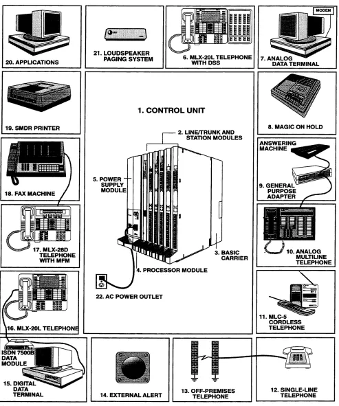
Figure 1-1 shows the components of a typical system. Your system may not have all the components pictured, or it may have additional or different components. The numbered items in the figure correspond to the descriptions that follow.
1 . 2 . 3 . 4 . 5 . 6 . 7 . 8 . 9 . 10. 11.
Control Unit. The backbone of the system, consisting of the basic and expansion carriers, power supply module, processor module, and trunk and station modules. The control unit connects telephone company trunks with stations such as telephones and adjuncts.
Trunk and Station Modules. The components that connect telephone company trunks and terminal equipment such as telephones, external alerts, and fax machines via jacks to the control unit.
Basic Carrier. The component attached to the backboard used to hold the modules needed for system operation. The basic carrier houses the processor module, power supply module, and up to five trunk and station modules. Each expansion carrier houses its own power supply module and up to six additional trunk and/or station modules. One or two expansion carriers can be added.
Processor Module. A miniature computer that controls most of the system’s features and supplies the system’s diagnostics. The processor module provides two jacks, one for Station Message Detail Recording (SMDR) and the other for system programming and maintenance via a personal computer (PC).
Power Supply Module. The component that supplies DC power for the modules and telephones (one power supply unit is needed per carrier). If the system’s power requirements exceed the capacity of the power supply module, an auxiliary power supply unit can be added.
Direct Station Selector (DSS). A console that adds 50 buttons for one-touch extension dialing to the MIX-20L™ or MLX-28D™ telephone and speeds call handling.
Analog Data Terminal. A data terminal such as a PC, printer, or optical reader that connects via a modem (for transmitting and receiving analog signals) to a 012 basic telephone module or a 008 OPT module. A data terminal can also be connected to an MLX telephone using a Multi-Function Module (MFM) or to an analog multiline telephone using a General Purpose Adapter (GPA.)
Magic on Hold®
. Optional equipment that connects to the system through a GS/LS jack programmed for Music-on-Hold. (A customer-provided music source can be connected instead of Magic on Hold.)
General Purpose Adapter (GPA). An adapter used to connect a variety of tip/ring (T/R) adjuncts to an analog multiline telephone (shown here with an answering machine).
Analog Multiline Telephone. A 34-button telephone with built-in
speakerphone that connects to the system via an analog station jack. Other analog multiline telephones compatible with the system include the 22- and 34-button with built-in speakerphone and a one-line, 16-character display and the 10- and 22-button with built-in speakerphone, without display.
13. 14. 15. 16. 17. 18. 19. 20.
Off-Premises Telephone (OPT). A single-line, touch-tone or rotary, industry-standard telephone located in a different building from the control unit.
External Alerts. Alerting devices such as bells, chimes, and strobe lights that connect to a jack on a 012 basic telephone module or a 008 OPT module, or to an MFM or Supplemental Alert Adapter (SAA).
Digital Data Terminal. A data terminal such as a PC, printer, or optical reader that connects via an ISDN 7500B Data Module to a 008 MLX module and that can also include an MLX telephone.
MLX-20L Telephone. A digital/lSDN (MLX) telephone with 20 line buttons and a display with seven lines of 24 characters each. The MLX-20L™ telephone can also be used as a system programming console. Other MLX telephones include:
■ MLX-10™/MLX-10D™ Telephone. A 10-button MLX telephone with or without a two-line, 24-character display.
■ MLX-28D™ Telephone. An MLX telephone with 28 line buttons and a
two-line, 24-character display.
Multi-Function Module (MFM). A circuit board mounted inside an MLX telephone that provides a jack to connect optional equipment such as answering machines, fax machines, external alerts, and modems to the telephone.
Fax machine. Industry-standard fax machines connected to the control unit via a jack on a 012 basic telephone module or a 008 OPT module, an MFM, or a GPA.
SMDR Printer. A printer for Station Message Detail Recording (SMDR) call records, connected via an RS-232 jack on the processor module.
Applications. Software and hardware for the MERLIN LEGEND™ Communi-cations System that can be connected to the control unit to provide more functions: ■ ■ ■ ■ ■ ■
Call Accounting System (CAS) Call Accounting Terminal (CAT) Call Management System (CMS)
MERLIN MAIL™ Voice Messaging System MERLIN® Attendant
Integrated Solution II (IS II)
Location of the Control Unit
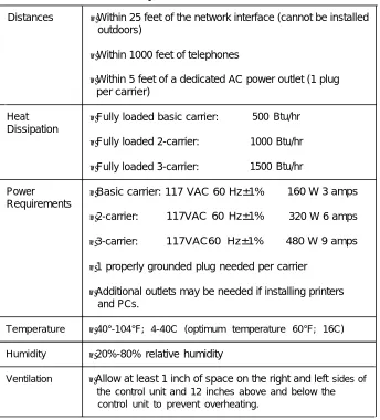
Before installation, choose a room, closet, or other area where the system control unit can be mounted on the wall. The area must meet the environmental requirements in Table 1-1.
Table 1-1 Environmental Requirements
Distances ■ Within 25 feet of the network interface (cannot be installed outdoors)
■ Within 1000 feet of telephones
■ Within 5 feet of a dedicated AC power outlet (1 plug per carrier)
Heat ■ Fully loaded basic carrier: 500 Btu/hr Dissipation
■ Fully loaded 2-carrier: 1000 Btu/hr
■ Fully loaded 3-carrier: 1500 Btu/hr
Power ■ Basic carrier: 117 VAC 60 Hz±1% 160 W 3 amps Requirements
■ 2-carrier: 117VAC 60 Hz±1% 320 W 6 amps
■ 3-carrier: 117VAC60 Hz±1% 480 W 9 amps
■ 1 properly grounded plug needed per carrier
■ Additional outlets may be needed if installing printers and PCs.
Temperature ■ 40°-104°F; 4-40C (optimum temperature 60°F; 16C)
Humidity ■ 20%-80% relative humidity
Ventilation ■ Allow at least 1 inch of space on the right and left sides of the control unit and 12 inches above and below the control unit to prevent overheating.
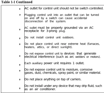
Table 1-1 Continued
■
■
■
■
■
■
■
■
■
■
AC outlet for control unit should not be switch controlled.
Plugging control unit into an outlet that can be turned on and off by a switch can cause accidental
disconnection of the system.
AC outlet must be property grounded via an AC receptacle for 3-prong plug.
Do not install control unit outdoors.
Do not place control unit near extreme heat (furnaces, heaters, attics, or direct sunlight).
Do not expose control unit to devices that generate electrical interference (such as arc welders or motors).
Each auxiliary power unit requires 1 outlet.
Do not expose control unit to moisture, corrosive gases, dust, chemicals, spray paint, or similar material.
Do not place anything on top of carriers.
Do not install under any device that may drip fluid, such as an air conditioner.
In addition, a 3/4-inch plywood backboard is needed to mount the system on the wall. The dimensions depend on the number of carriers, as shown in Table 1-2. in some areas, fire or electrical codes require a flame retardant backboard. Check with the appropriate authorities to ensure that the proper material is provided.
Table 1-2 Control Unit Space Requirements
Carrier Dimensions
Telephone User Survey
The features and calling privileges you assign to each employee’s telephone ensure that employees get the most benefit from the system.
If you were not involved in the planning and decision-making for the system, find out from your management and your AT&T representative or authorized dealer what telecommunications needs were identified.
To determine calling privileges, get answers to the following questions:
■
■
■
■
■
■
Does management want to allow both local and toll calls to be made from every telephone?
If any telephones are restricted, are there any numbers the users should be allowed to call?
Are there any specific numbers (such as 900) that you want to restrict users from calling?
Who, if anyone, will be given personal lines?
Will access to central office trunks (outside lines) be restricted to certain employees?
Do any departments receive frequent special calls (such as sales and service) so that calls should come to them directly, bypassing a system operator?
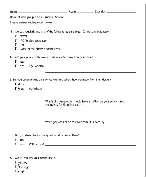
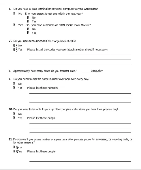
Use the Employee Communication Survey form (see Figure 1-2) to determine each employee’s telecommunications needs. If it is not feasible to have each employee fill out a form, get the information you need from a knowledgeable person in each department, section, or work group. This person should have sufficient information and authority to make decisions about calling features and coverage assignments for others in the department.
Name Room Extension
Name of work group (Sales, Customer Service)
Please answer each question below.
1 .
2.
Do you regularly use any of the following
❑
❑
❑
❑
Are
❑
❑
outside lines? (Check any that apply)
WATS
FX (foreign exchange) Tie
None of the above or don’t know
your phone calls covered when you’re away from your desk?
No
Yes By whom?
3. Do you cover phone calls for co-workers when they are away from their desks?
❑
N o❑
Yes For whom?Which of those people should have a button on your phone used exclusively for his or her calls?
When you are unable to cover calls, it is done by
6.
7 .
8.
9.
Do you have a
❑
❑
Do
❑
❑
No D O
❑
❑
Yes Do
❑
❑
data terminal or personaI computer at your workstation?
you expect to get one within the next year? No
Yes
you have a modem No
Yes
or ISDN 7500B Data Module?
you use account codes for charge-back of calls?
No
Yes Please list all the codes you use (attach another sheet if necessary):
Approximately how many times do you transfer calls? times/day
Do
❑
❑
you need to dial the same number over and over every day?
No
Yes Please list these numbers:
10. Do
❑
❑
you want to be able to pick up other people’s calls when you hear their phones ring?
No
Yes Please list these people:
11. Do you want your phone number to appear on another person’s phone for screening, or covering calls, or for other reasons?
❑
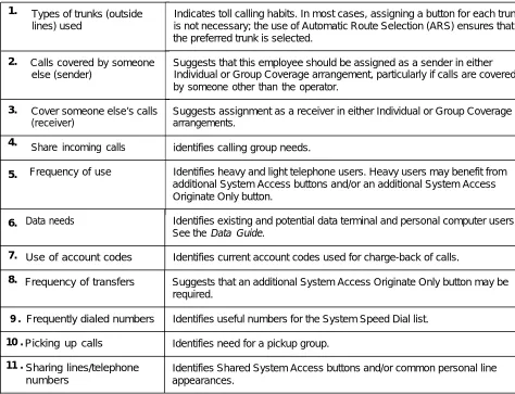
N oUse the information in Table 1-3 to interpret and analyze the results of the employee communication survey.
Table 1-3 Employee Communication Survey — Sample Analysis
1.
2.
3.
4.
5.
6.
7.
8.
Types of trunks (outside lines) used
Calls covered by someone else (sender)
Cover someone else’s calls (receiver)
Indicates toll calling habits. In most cases, assigning a button for each trunk is not necessary; the use of Automatic Route Selection (ARS) ensures that the preferred trunk is selected.
Suggests that this employee should be assigned as a sender in either Individual or Group Coverage arrangement, particularly if calls are covered by someone other than the operator.
Suggests assignment as a receiver in either Individual or Group Coverage arrangements.
Share incoming calls
Frequency of use
identifies calling group needs.
Identifies heavy and light telephone users. Heavy users may benefit from additional System Access buttons and/or an additional System Access Originate Only button.
Data needs Identifies existing and potential data terminal and personal computer users. See the Data Guide.
Use of account codes Identifies current account codes used for charge-back of calls.
9 .
10 .
11 .
Frequency of transfers Suggests that an additional System Access Originate Only button may be required.
Frequently dialed numbers Identifies useful numbers for the System Speed Dial list.
Picking up calls Identifies need for a pickup group.
Sharing lines/telephone Identifies Shared System Access buttons and/or common personal line
Floor Plan
Use a floor plan to make planning more manageable and to ensure that the correct telephone equipment is assigned to each employee.
If your organization is moving to a new location, a floor plan may already be prepared and you may be able to get a copy of it from your management.
Create a floor plan in two phases:
1. Indicate the location and type of telephones, adjuncts (fax, answering machines, etc.), and data terminals.
2. When you assign extension numbers, indicate the assigned numbers on the floor plan.
Note: In this book, telephones and associated adjuncts, such as answering machines or data terminals, or adjuncts connected directly to the control unit, are called stations.
1 .
2 .
3 .
4 .
Planning Instructions
Use a large sheet of paper and sketch your office layout. The location of office walls and other partitions is important when features are assigned to telephones that must be within hearing range of each other. For example, pickup group members must be able to hear each others' telephones rigning.
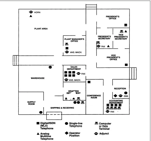
Indicate the location of each employee's telephone, other locations where there will be a telephone (such as in a conference room), and the locations of data terminals, PCs, and host computers. Use the symbols shown in Figure 1-3.
Indicate the tupe of telephone at each location, using an abbreviation that includes the number of programmable buttons. For example, write "MLX-10" at 10-button MLX telephones, "MLX-20L" at 20-button MLX display telephones, "BIS-34" at 34-button analog multiline telephones, and so forth.
Planning the control unit consists of deciding how to place the modules, setting the system operating conditions, and numbering the system.
Modules
Certain modules are required for every system:
■ Processor module contains the memory that controls the system software and features. It also contains the software and firmware that supports built-in system diagnostics and the built-in data modem used for remote
maintenance and system programming. The processor module is offered in two sizes:
■ The small processor module supports a maximum of 24 trunks and/or 56 stations.
■ The large processor module supports a maximum of 80 trunks and/or 144 stations.
■ Power supply module provides power to the processor module and trunk and station modules, and to each telephone and adjunct. Each carrier in the control unit has one power supply module.
■ Trunk and station modules contain the jacks for connecting stations and outside trunks to the control unit. The type of jack on a module determines the type of trunk or station that can be connected to it.
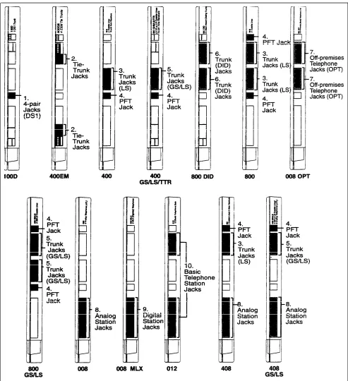
The trunks and stations that can be connected to the jack types shown in Figure 2-1 are described below:
1.
2.
3.
4.
5.
6.
7.
8.
See the Data Guide for more information 9. on data stations
10.
A DS1 trunk jack connects a Digital Signal 1 (DS1) facility provided by the telephone company. The DS1 facility can be set for either T1 or integrated Services Digital Network Primary Rate Interface (ISDN-PRI) operation.
The DS1 facility programmed for T1 operation supplies 24-channel emulation of any combination of ground-start (GS), loop-start (LS), and tie trunks. When programmed for PRI operation, the channels are used to connect ISDN services such as Megacom®
WATS.
Tie-trunk jacks connect private lines from other communications systems.
Trunk jacks (LS) connect loop-start trunks from the telephone company.
(PFT) jacks connect single-line telephones that work during power failures. Analog multiline telephones and digital/lSDN (MLX) telephones cannot be used as power failure telephones.
Trunk jacks (GS/LS) connect loop-start or ground-start trunks from the telephone company.
Trunk (DID) jacks connect Direct Inward Dial (DID) trunks.
Off-premises telephone (OPT) jacks connect off-premises tip/ring equipment such as single-line telephones, fax machines, or answering machines. Tip/ring equipment connects directly to an outside trunk and works on a single pair of wires.
Analog station jacks connect analog multiline telephones and adjuncts.
Digital station jacks connect MLX telephones or data devices such as the ISDN 7500B Data Module.
Basic telephone station jacks connect tip/ring equipment such as single-line telephones, fax machines, or answering machines. Basic telephone station jacks also connect optional applications such as MERLIN Attendant or MERLIN MAIL Voice Messaging System for the MERLIN LEGEND Communication System.
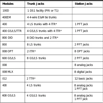
Table 2-1 Module Capacities
Modules
100D
400EM
400
400 GS/LS/TTR
800 DID
800
008 OPT
600 GS/LS
008
008 MLX
012
408
408 GS/LS
Trunk Jacks
1 DS1 facility (PRI or T1)
4 4-wire E&M tie trunks
4 LS trunks with 4 lTR*
4 GS/LS trunks with 4 lTR*
8 DID trunks and 2 lTR*
8 LS trunks
2 ITR*
8 GS/LS trunks
2 TTR*
4 LS trunks
4 GS/LS trunks
Station Jacks
1 PFT jack
1 PFT jack
2 PFT jacks
8 OPT jacks
2 PFT jacks
8 analog jacks
8 digital jacks
12 basic jacks
8 analog jacks 1 PFT jack
8 analog jacks 1 PFT jack
Trunk and Station Capacity
Planning Form Instructions
Under the section "Size of Processor Module," check the box describing the size of the processor module (small or large).
Under the "Trunks" headin in the "Capacity" section:
1 .
2 .
3 .
4 .
Fill in the number of each type of trunk module on the appropriate line.
Add the column and record the result next to the system totals.
Multiply the number of each type of module by the number of trunks it supports. Write the results in the "Total Trunks by Module Type" column.
Add the column and record the total tyrunk capacity of the system.
See "System Numbering” in this chapter for detailed information.
The numbers of jacks in Table 2-1 are the physical jacks on each module. In most cases, the number of physical jacks indicates capacity (the number of trunks and/or stations that can be connected to the module). The exception is the 100D module, with one physical jack, which because of the system’s software capabilities supports 24 trunks.
Use the AT&T Equipment List (supplied with your system) to complete page 1 of PBX System Form 1, System Planning.
Station capacity is the number of stations that can be connected to the control unit, and it equals the number of physical jacks on the trunk and station modules.
One extension number is automatically assigned to each station jack, whether or not equipment is connected to it, except for the 008 Ml-)( and 008 OPT modules:
■ 008 MLX module has two extension numbers assigned to each physical jack, the first for a digital/lSDN (MLX) telephone and the second for any equipment connected to the telephone through an MFM.
■ 008 OPT module has eight physical jacks, which the system reads as 12 jacks and assigns an extension number to each.
Planning Form Instructions
Under the heading "Stations":
1.
2.
3.
Fill in the numbers of each type of station module on the appropriate lines.
Add the column and record the result by System Totals.
To determine the number of extensions assigned:
5.
6.
7.
Multiply the number of physiocal jacks by module type by the number of station extensions the system assigns to each module's jack type.
N O T E : Since the system assigns an additional four extensions to each 008 OPT module you must multiply the number of 008 OPT modules by four and add this subtotal to the result shown in the "Physical Jacks by Module Type" column.
Write the results in the "Total Station Extension Assigned" column.
Add the column and fill in the "System Totals" line.
Module Placement
See “Station Jack Connections” in this chapter for information on QCCs
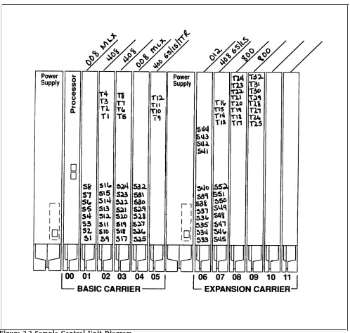
Use the “Control Unit Diagram” on PBX System Form 1 and the following guidelines to plan where the modules are placed in the control unit:
■ Put the power supply module in the far left slot of each carrier.
■ Put the processor module in slot 00 of the basic carrier.
■ Put trunk and station modules in any order in slots 01 through 17, with the following conditions:
Put the modules in each carrier from left to right with no empty slots between modules. (The system does not acknowledge modules in slots that follow an empty slot; slots to the right of the last module can be left empty.)
If the system includes a queued call console (QCC), make the 008 MLX module the first station module (located to the left of any 008, 408, or 408 GS/LS modules).
Put all 012 and 008 OPT modules in the same carrier whenever possible (These modules use a frequency generator.)
Group all 800 DID, 100D, and 400EM modules together according to type, whenever possible, to save time in system programming.
Each physical jack on the control unit is numbered sequentially from left to right and bottom to top:
Notes:
■ Each 100D module is assigned 24 logical IDs even though the module has only one physical trunk jack.
■ The 008 OPT module is assigned 12 logical IDs even though the module has only eight physical station jacks.
■ Power failure transfer (PFT) jacks are not assigned logical IDs.
Planning Form Instructions
Mark the module placement on the "Control Unit Diagram" on the back of Form 1.
1 .
2 .
Note:
■
■
Write the type of module to be installed at the top of each slot. Use the labels listed in Tabvle 2-1 (008 MLX, 408, etc.).
Write the type of jack (S=station, T=trunk) and the associated logical ID for each trunk and station jack on each module.
The "Unit Load" block above the diagram are reserved for occasions when equipment changes or maintenance require the installation technician to manually compute the values. See System Reference for details on computing unit loads.
Logical ID labels for each trunk and station jack are provided with the system. When the control unit is assembled, the labels are attached to the modules.
System Operating Conditions
Record the following system operating conditions:
programming equipment that will be used and its station jack assignment
mode of operation
whether Automatic Maintenance Busy is enabled
a reminder to set the system time and date
Use the “Control Unit Diagram” on PBX System Form 1 as a reference and mark the “System Operating Conditions” section of that form.
Programming Equipment and Station Jack Assignment
Two types of equipment can be used for system programming:
■ an MLX-20L telephone acting as a system programming console. The telephone is the first (lowest) station jack on the first MLX module and is factory set for system programming.
■ a personal computer (PC) with MERLIN LEGEND System Programming and Maintenance (SPM) software. (Both DOS- and UNIX†-based SPM are available.) The PC is connected to the lower jack on the processor module.
Planning Form Instructions
Under the heading, "System Programming Console," on Form 1:
1 .
■
■
2 .
Note:
D o o n e o f t h e f o l l o w i n g :
Check "No" if you are using a PC with SPM to program the system. Go to the "Mode of Operation" instructions.
Enter the Logical ID and Extension Number if you are using a system programming console.
To change the factory-set system programming jack, write in the new logical ID (using the information from the "Control Unit Diagram").
Y o u w i l l f i l l i n t h e e x t e n s i o n n u m b e r o f t h e j a c k l a t e r .
In addition to being factory set for system programming, the first (lowest) station jack on the first MLX module is also factory set as the primary operator position. Since the primary operator position cannot be reassigned to another station jack, you may want to change the system programming assignment to ensure that future programming sessions do not interfere with the operator’s work.
Mode of Operation
See System Reference for more Your system is registered with the FCC to operate as either a Private Branch
information on modes. Exchange (PBX) or Hybrid system. However, you can program the system to
operate in any of three modes:
■ Hybrid/PBX
■ Key (the factory setting)
■ Behind Switch
The mode of operation determines
■ how outside trunks are provided to users
■ the types of operator consoles allowed
■ the features available and how they work
Note: This book applies only to systems in the Hybrid/PBX mode. To plan a system in either the Key or Behind Switch mode, use Key System P/arming.
Hybrid/PBX Mode
See System Reference for information The Hybrid/PBX mode handles large volumes of calls and telephone users, and on trunk types. offers the most flexibility of the three modes. Outside lines, called trunks, can be
loop-start, ground-start, Direct Inward Dial (DID), DS1, or tie. The outside trunks can be grouped in pools for shared use. In addition, outside trunks can also be assigned to line buttons on multiline telephones for users who require a personal line.
Users access inside lines and outside trunks via System Access buttons. To make an outside call, the user enters a dial-out code, usually a 9, and the system automatically selects an available trunk. The Automatic Route Selection feature determines which trunk is used for each type of outgoing call.
Incoming calls can be handled by either a direct-line console (DLC) or a queued call console (QCC), or a combination of both. Calls handled by QCCs are directed to a QCC queue, where they are held until an operator is available.
Planning Form Instructions
Automatic Maintenance Busy
Automatic Maintenance Busy puts a malfunctioning trunk in a “maintenance busy” state, preventing outgoing calls on that trunk. Incoming calls are never blocked. A trunk in maintenance busy is tested by the internal maintenance software to try to put it back into service.
The factory setting for Automatic Maintenance Busy is “disabled,” which means that faulty trunks are not automatically put in a maintenance busy state. If you `pIan to group trunks into pools, enable Automatic Maintenance Busy for optimum system performance.
Planning Form Instructions
Under the "Automatic Maintenance Busy" heading of Form 1:
1 .
2 .
Check "Disable" to keep the factory setting.
Check the second box to enable Automatice Maintenance Busy.
System Date and Time
See “System Features” in Chapter 4 for The system date and time is the month, day, year, and time shown on display information on SMDR. telephones and Station Message Detail Recording (SMDR) reports. The system
date and time is also shown on error reports used by AT&T or an authorized representative for maintenance.
Planning Form Instructions
System Numbering
System numbering is the process of assigning extension numbers to stations (telephones and adjuncts), calling groups, paging groups, park zones, and remote access.
The instructions in this chapter deal only with assigning extension numbers to stations.
Number the stations in two stages:
Stage One. Decide in what order to connect the telephones and other equipment to the control unit. To do this, identify station jack types and match individual components with the jacks that support them.
When the system is turned on, it identifies the type of module installed in each control unit slot and automatically assigns extension numbers to the
components in exactly the same order in which they are connected to the control unit. As you plan connections, therefore, you should be aware of the relationship between the jack’s logical ID and the extension number the system assigns.
The stations are assigned 2-digit extension numbers starting with extension 10 at the station jack with the logical ID of 1. If a user needs a specific extension number, it is simpler (in terms of programming) to connect that user’s telephone to the station jack that is automatically assigned the requested extension number.
Stage Two. Decide if the system-assigned extension numbers are appropriate or if you should renumber all, or some, of the extensions assigned. to the stations.
The system offers three predetermined numbering plans. In addition, you have the option of creating your own unique numbering plan with extensions of one to four digits.
Planning Form Instructions
Station Jack Connections
Planning station jack connections consists of identifying the jack types and matching the telephones and other equipment to the jacks that support them. Determine the station jack types in the control unit and plan connections in the following order:
primary operator position
additional operator positions
Voice Announce to Busy and/or Simultaneous Voice and Data
digits!/lSDN (MIX) telephones
analog multiline telephones
tip/ring equipment
applications
Station Jack Types
Station jack type is determined by the module type. The station jack types and the equipment that can be connected to these jacks are listed in Table 2-2.Use the completed “Control Unit Diagram” (Form 1) and Table 2-2 for reference and mark the station jack types on Form 2a.
Table 2-2 Station Jack Types
Station Jack Type Analog Module Type 008 408 408 GS/LS
Digital 008 MLX
Basic 012
Telephone
Used to Correct
Analog multiline telephones Call Management System (CMS)
Digital/lSDN (MLX) telephones
Digital data devices, such as ISDN 7500B Data Modules
Tip/ring equipment: Single-line telephones
Adjuncts, such as answering or fax machines
Analog data devices, such as modems Optional applications:
MERLIN Attendant
MERLIN MAIL Voice Messaging System AUDIX Voice Power—lS II
Planning Form Instructions
In the "Jack Type" column of Form 2a, indicate the type of each station jack next to its logical ID.
1 . Check "A" if the jack is analog, "D" if digital, or "B" if basic telephone. 2. The system reserves 12 logical IDs for the 008 OPT module even though
only 8 are used. Cross off the last 4 logical IDs (they cannot be used).
Jacks for Primary Operator
Position
The factory setting for the primary operator position is the lowest station jack on the first 008 MLX module. If the system doesn’t have an Ml-x module, it’s the lowest station jack on the first module with analog station jacks. The factory setting for the primary operator position cannot be changed.
Two types of operator consoles can be used in the primary operator position:
■
■
Direct-Line Console (DLC). Trunks are assigned on individual buttons; the console can have several calls ringing simultaneously. DLCs can be assigned to either a digital or analog station jack.
Queued Call Console (QCC). Incoming calls are held in a queue and are directed to each QCC in sequence, one at a time. QCCs can be assigned only to digital station jacks, and the MLX-20L is the only phone that can be used as a QCC.
If the system includes QCCs, the primary operator position must be a QCC.
Planning Form Instructions
M a r k j a c k a s s i g n m e n t s o n F o r m 2 a .
If the system does not include a system programming console, go to step 4.
1 . See the "System Operating Conditions" section on the back Form 1 for the logical ID of the station jack for the system programming console.
2 . Mark the "Logical ID" column of Form 2a by writing "SPC" beside the preprinted logical ID for the system programming console station jack.
Planning Form instructions - Continued
If the system includes only DLCs.
6 . Locate the first station jack showing a "D" (digital) or "A" (analog) type. Write "DLC" beside the preprinted logical ID to indicate the primary DLC operator position.
7 . Write the name or location of the primary DLC operator in the "Person, Location, or Function" column.
Jacks for Additional Operator Positions
Use these instructions only if the system has more than one operator position.
The maximum numbers of both types of operator position are shown in Table 2-3.
Table 2-3 Maxim
Positon Type
Q C C
DLC
DLC
DLC
um Number of Operator Positions
Telephone Processor Maximum
Type Module Size Positions
MLX-20L Small or Large 4
MLX-20L Small 6
MLX-28D
MLX-20L Large 8
MLX-28D
Analog multiline Small or Large 8 telephones
Any combination of operator positions can be assigned as long as no more than four are QCCs and the total combined number is no more than six for a small processor module or eight for a large processor module. For example, a system with a small processor can have a combination that consists of four QCCs and two DLCs. Or, a system with a large processor can have a combination that consists of four QCCs, two digital/lSDN DLCs, and two analog DLCs.
Operator positions can be assigned as follows:
Assign QCC positions to only the first and fifth station jacks on a digital module.
Assign DLCs to only the first and fifth station jacks on a digital or analog module. This includes DLC positions used for calling group supervisors and for the optional Call Management System (CMS).
Planning Form Instructions
Use the "Control Unit Diagram" on Form 1 to determine which station jacks can be used as operator positions:
1 . Circle the first and fifth station jacks on each digital or analog module on the "Control Unit Diagram" until you have reached the maximym eaight positions.
2 . Mark the station jacks to be used as additional operator positions on Form 2a.
If the system does not have QCCs, go to step 5.
3 . Write the "QCC" beside the preprinted logical ID for each additional QCC position. Be sure to assign QCCs to only the first and fifth station jacks on each digital module.
4 . Write the name or location of each additional QCC operator in the "Person, Location, or Function" column.
5 . Write "DLC" beside the preprinted logical ID for each additional DLC position. Be sure to assign DLCs to only the first and fifth station jacks on each digital or analog module.
6. Write the name or location of each additional DLC operator in the "Person, Location, or Function" column.
7 . If the system includes Call Management System(s), write "CMS" in the "Person, Location, or Function" column next to the logical ID for the two DLC positions assigned for each CMS.
Station Jack Pairs
Use these instructions only if the system has analog multiline telephones.Two of the optional features for analog multiline telephones require an additional station jack:
Voice Announce to Busy. A user whose telephone has this feature can hear an announcement through the speaker even though he or she is on a call. (MLX telephones can also use this feature but do not need an additional station jack. Single-line telephones cannot use this feature since they do not have speakers.)
Planning Form Instructions
On Form 2a, mark the pairs of jacks for analog multiline telephones that have the Voice Announce to Busy or Simultaneous Vioce and Data feature.
1 . In the "Logical ID" column, draw a box around the pair of station jack numbers that you plan to assign to each analog multiline station with either feature.
2 . In the "Person, Location, or Function" column, next to the first (odd) number of each boxed pair, identify the station by person or location.
3 . In the "Person, Location, or Function" column, next to the second (even) number of each boxed pair, write "voice/voice" for the Voice Announce to Busy feature or "voice/data" for the Simultaneous Voice and Data feature.
Jacks for Digital/ISDN
(MLX) Telephones
Use the instructions in the Data Guide to plan connections for digital data equipment.
The system assigns individual extension numbers to each of the jacks for either the Voice Announce to Busy or the Simultaneous Voice and Data feature. The extension number associated with the first (odd-numbered) station jack in the pair is the telephone’s extension number. Calls cannot be placed to the extension number associated with the even-numbered station jack.
You can assign either of these features to any of the analog multiline telephones in the system, but you cannot assign both to the same telephone.
Use these instructions only if the system has non-operator MLX telephones to assign to digital station jacks on 008 MLX modules.
Although only one logical ID is assigned to each digital station jack, the system assigns two extension numbers. The extension number on Form 2a is the extension number automatically assigned to an MLX telephone connected to the digital station jack. The second extension number is reserved for an adjunct such as an answering machine that may be connected to the MLX telephone via a Multi-Function Module (MFM) or for an ISDN 7500B Data Module used to connect a data terminal.
The system automatically assigns both extension numbers whether or not the station includes an MFM or data module. Calls can be placed to both extension numbers independently.
Planning Form Instructions
Use the Floor Plan and AT&T Equipment List to verify that you have located all remaining MLX telephones and adjunts connected to them.
On Form 2a, mark the station jack assignments for the remaining MLX telephones.
1. In the "Jack Type" column, make sure there is a "D" checked next to the
2. In the "Person, Location, or Function: column, identify each MLX
Use the information from Form 2a as you mark the difital station adjuncts on PBX System Form 2b, System Numbering - Digital/ISDN Station
A d j u n c t s .
3. In the "Logical ID" column, write the logical ID of each digital station jack (D jack type).
Note: You will fill in the "Factory-Set Extension No." column later.
Complete the "MFM" and "7500B" columns.
4 . If the jack does not have an adjunct connected, write "None" across the columns.
5 . If an adjunct is connected to the MLX telephone:
■ Check "SAA" or "T/R" in the "MFM" column to show how the MFM connects the adjunct.
■ Check the "7500B" column if the station includes the data module.
6. Complete the last column.
7. Identify each adjunct or data module by type and by person, location, or function.
Jacks for Analog Multiline Telephones
Use these instructions only if the system includes the 408,408 GS/LS, or 008 modules.
Jacks for Tip/Ring Equipment and Applications
See System Reference for more information on applications.
Use these instructions only if the system includes 012 or 008 OPT modules.
Assign the basic telephone jacks on the 012 or 008 OPT modules to any tip/ring equipment such as single-line telephones, fax machines, or answering
machines. Tip/ring equipment connects directly to an outside trunk and works on a single pair of wires. When connected to a 008 OPT module, the tip/ring equipment can be located off premises.
Several optional applications, if used with the system, require a basic jack on a 012 module: MERLIN MAIL Voice Messaging System, MERLIN Attendant, AUDIX Voice Power—lS II, and Integrated Voice Power Automated Attendant— IS Il.
Up to four applications can be connected to the system using the same 012 module. If there are four applications, the module must be used exclusively for this equipment. If you have fewer than four applications connected to a 012 module, some tip/ring devices can also be connected. If possible, the module should be used only for the application equipment.
Note: The applications discussed here do not work properly with 012 modules manufactured for older MERLIN®
II systems. These applications must be connected to 012 modules with the code 517C13 or 517D13 on the label on the top of the module. Modules with the code 517A13 or 517B13 can be used to connect only single-line telephones and do not provide the disconnect signal required by answering machines and applications.
Planning Form Instructions
On Form 2a, mark the station jack assignments on the 012 and 008 OPT modules:
1 . In the "Jack Type" column, make sure there is a "B" checked next to the logical ID for each basic telephone jack.
2. In the "Person, Location, or Function" column, identify each tip/ring device by person or location and by type, such as single-line telephone, fax, or answering machine.
3 . If the system includes optional applications, indicate the type of application in the "Person, Location, or Function" column:
■ Write "Mail" to idicate MERLIN MAIL Voice Messaging System.
■ Write "MERLIN A" to indicate MERLIN Attendant.
■ Write "AVP" to indicate AUDIX Voice Power-IS II.
System Renumbering
Use these instructions to decide whether to keep the factory-set extension numbers or change them to numbers tailored to your company—for example, extension numbers that match room numbers.
The system offers three numbering plans, as shown on Form 2a, System Numbering — Station Jacks. Each plan allows you to renumber all or selected extensions:
Two-Digit- designed for systems with fewer than 50 stations at businesses that do not anticipate growth to more than 50 stations in the next one or two years. The two-digit numbering plan is the factory setting.
Three-Digit- designed for businesses with more than 50 stations.
Set Up Space- designed for businesses that want to customize numbering and assign 1- to 4-digit extensions that are more convenient for users. As an example, hotels and motels may want to renumber extensions to match room numbers and to renumber services numbers (such as Housekeeping or Room Service) to 1-digit extension numbers.
When you reassign extension numbers, keep the following in mind:
Extension numbers can c