Analysis on the Buckling Behavior of the Spacer Grid Structure for the P W R Fuel
Assembly
K. H. Yoonl), K. N. Songl)
1) Advanced Reactor Development Division, Korea Atomic Energy Research Institute, Taejon, Korea
ABSTRACT
The objective of this research is to propose the methodology that could predict the buckling behavior on the spacer grid structure for the PWR(P_ressurized Water Reactor) fuel assembly. To perform this objective, the two kinds of approach are used in this work. First, in order to obtain the test data on the dynamic buckling behavior of the spacer grid, the impact test is performed with the 5x5 cell size partial grid specimen, which is made of Zircaloy-4 thin plate. Second, a finite element analysis method for predicting the buckling behavior on the spacer grid structure is established by a commercial finite element code ABAQUS/Explicit. In this FE analysis method, appropriate boundary conditions and impact loading conditions are applied to simulate the actual test conditions. From the impact test, the dynamic buckling phenomenon depends on the weakest layer cell, which is so called local buckling of the metal structure. In addition, the finite element analysis model is in good agreement with the impact test results, therefore this finite element model and the analysis procedure will be used aa a good tool for predicting the dynamic buckling behavior of the grid structure.
INTRODUCTON
The fuel assembly is mainly composed of a top-end piece, a bottom-end piece, lots of fuel rods, several guide thimbles and several spacer grids[ 1 ]. Among them, the spacer grid is a structural component which is designed to provide important functions such as supporting the fuel rods, guiding cooling water, resist against the external dynamic impact loading, and so on. Therefore, for secure operation abrasion on fuel rods and flow-induced vibration have to be considered when designing the grids. Furthermore, one of the most important roles of the spacer grid is to protect the fuel assembly from the unexpected extreme load caused by dynamic external load for example, an earthquake. It is necessary to have sufficient strength against buckling loads, of course the longer the spacer grid strip height, the stronger the critical strength of the grid. However, the longer the spacer grid strip height is caused the excessive pressure drop in the core. It is an important cause for power drop because the excessive pressure drop is decline the design margin of the DNB(Departure of N__uclear Boiling). Therefore, the optimized strip height is necessary to have the sufficient impact strength and to increase the DNB margin in design. The spacer grid is composed of straps, which are crossed to form an egg-crate like structure. It constitutes the skeleton of the fuel assembly together with guide thimbles, top and bottom end pieces. The structural grid assemblies provide both lateral and vertical support for the fuel rods. The pitch of the fuel rods in the core is a carefully selected parameter, which has a major effect on the nuclear and thermal/hydraulic performance of the core. The spacer grid is an interconnected array of slotted grid straps welded at the intersections. The fuel assembly incorporates from seven to eleven spacer grids. The spacer grid outer straps constitute the contact surfaces that can transmit possible seismic loads between the fuel assemblies. The principal design concern with regard to grid strap buckling is that the fuel rods should maintain a coolable geometry and that the control rods should be inserted. The design practice is to adopt the incipient buckling load as a failure criterion for the grid. The diagonal axis of the grid assembly has the lowest impact strength. Sustained loads applied along the diagonal axis, however, are not credible because slipping between grid assemblies causes diagonal loads to be applied to the grids in normal directions only. Consequently, the limiting loads imposed upon the grid assembly are the result of impacts due to lateral seismic accelerations, lateral LOCA (Loss Of Coolant Accident) blowdown forces, and shipping and handling loads. The ability of the grid to resist lateral loads is characterized in terms of its dynamic and static crush strengths. These quantities and the grid dynamic stiffness are required for fuel assembly seismic and LOCA blowdown analyses to verify that the coolable grid geometry is maintained.
In this paper, the pendulum type impact test is performed on several partial spacer grids, which are made of Zircaloy-4 sheet material and composed of the 5x5 cell size. In this test, the test data are acquisited the impact force, impact acceleration versus initial angle of the impact hammer. These test data are acquisited from the sensors, which attached the impact hammer, such force transducer and accelerometer. The impact force is decreased after the critical initial impact angle in spite of the increase the hammer angle. It is decided the critical value of the specimen. This critical value is variated as specimen
SMiRT 16, Washington DC, August 2001 Paper # 1538
condition, such that the grid manufacturing, welding condition, and test error, and so on. Therefore, the critical value is an average of these test data as specimens.
In addition to this impact test, the finite element method is applied for predicting the critical impact velocity, impact force and buckling shape. The finite element model is produced the pre-processor, I-DEAS master series Ver. 7m112], and solved the dynamic problem using the commercial finite element analysis code, ABAQUS/Explicit Ver. 5.8[3]. This FE analysis model is created using the 4-node shell element for structure, and the 4-node rigid element for impact hammer. The total analysis time is 40 milli seconds for considering the impact event The applied boundary condition is considered the actual boundary for the impact test, the impact force is calculated from the summation and the reaction forces of the displacement constrained edge.
IMPACT TEST
Test Apparatus Setup
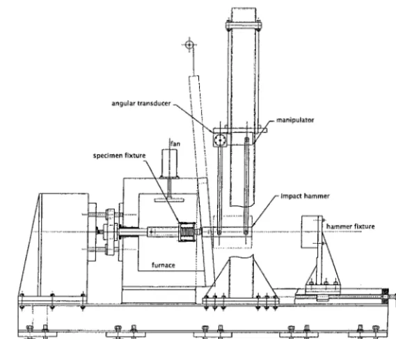
A pendulum type shock machine, as shown in Figure 1, is used to perform the impact test of the partial spacer grid structure. It is intended to simulate the type of load and impact velocities anticipated under a seismic disturbance. This shock machine is composed of a structural body, impact hammer, data acquisition system and furnace. The impact hammer is composed a sphere type impact tip for dynamic loading, two sensors for gathering the dynamic data, which are two force transducers(PCB 202B) and one accelerometer(PCB 353B03). An angular transducer is attached at the hinge point of the impact hammer. That is for detecting the initial angle of the hammer and continuous data on angle of it. The data acquisition system consists of a magnetic controller, two dynamic signal amplifiers, a temperature controller. The impact hammer moves with the guidance of the four guide rods. The impact hammer is made of mild steel, which mass corresponds to the mass of one span of the partial spacer grid. The manipulator at the hinge point of the impact hammer is made for accurate impact point regardless of specimen size. The general test setup consists of the floor, hammer weight, force transducer, dynamic accelerometer, and mounting fixtures. The total moving mass is 13.4 kg, which contains the dummy weight, four connecting rods, force transducer and dynamic accelerometer. A furnace is for impact testing under the room temperature and high temperature condition, which correspond to the operating temperature in the core. This furnace is able to ascend over the operating temperature of the core. And the temperature deviation of the furnace inside is controlled within 5 degree Celsius. The grids are rigidly clamped to the holding plate that is also placed by clamping fixture in the furnace. The initial impact angle of the impact hammer is 10 degrees. The increment drop angle is one degree till decreasing the impact force and acceleration. The impacting tests were performed on 5×5 cell array grids. The grids are fixed to the holding fixture by two screws. The impact hammer is held by a magnetic holder and releases the hammer as release signal on the controller is activated.
Test Specimen
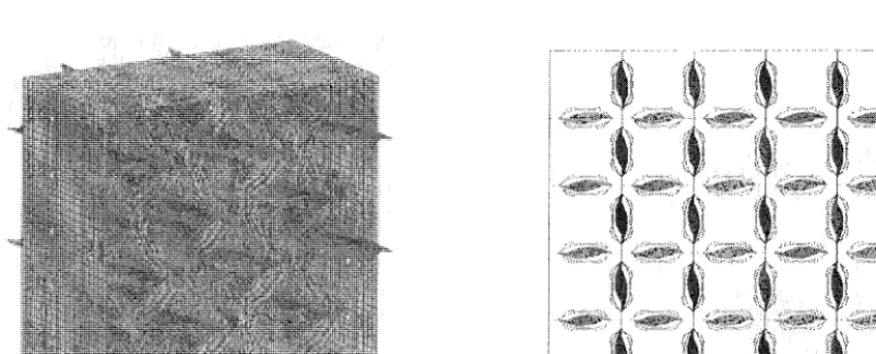
The 5x5 cell array grid size for PWR fuel assembly is manufactured with Zircaloy-4 thin plate, which thickness of the inner and outer strip is 0.457 mm and 0.664 mm, respectively. The unit plates are inserted in each other and welded at the cross-point and contact surface to compose the grid cell using the laser welding procedure. A photograph of the 5x5 cell partial grid structure is shown in Figure 2.
Impact Test Results
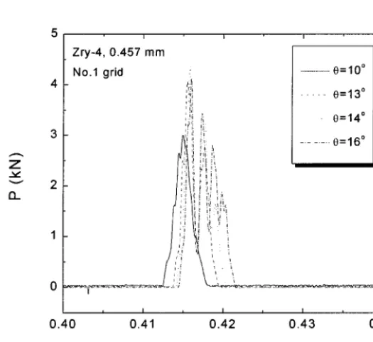
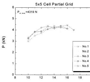
The impact force and acceleration during the test is a half sine signal in the time domain. The test data, initial hammer angle, impact velocity and acceleration of the hammer are shown in Fig. 3. In this figure, the hammer angle variation shows the trace for the impact event. The peak impact acceleration and impact velocity displayed at the zero degree of the hammer. The duration time for impact loading is extremely short. That is about 6 milli seconds. After the first impact, the secondary impact loading appeared about 0.6 seconds after primary impact. However, this secondary impact load is smaller than that of primary impact. Therefore, this secondary impact force and acceleration is a negligible value. The time-history data is obtained from the impact test and shown in Figure 4. If some grid cells experience local buckling, the duration time is longer than before the buckling state. This means that the stiffness of the grid structure after buckling is much smaller than before the buckling phenomena. As a test result, the normal duration time is about 6 milli seconds as the geometry of the specimen. The impact force range of the 5x5 cell grid specimen at the buckling point is from 4148 N to 4419 N and the impact acceleration range is from 33.85 g to 37.81 g. These variations were caused by the difference of the geometrical dimension and residual stress by welding as the specimen and non-uniform contact surface between impact hammer and top surface of
,:1
J
the specimen. The average values are 4319 N and 34.94 g, respectively. The results of the test are summarized in Figure 5.
angular transducer
specimen fixture If an
manipulator
furnace
h a m m e r
hammer fixture
' 'L i'i ' ' liJ ' ' lJl
Fig. 1 A Pendulum Type Shock Machine
:~ ... ... ... ,, .... 9i~.:,~i I:. '~ !:4 .... ... . ... ...
'~i,i:~d i:ii i'~i!i:~!i:,~
. . .
:,s!::
'~i
~ /
' ::.: ~::::~(i::i:f~i:::. ~ ::~ :~;ii::i~iiiii ~~!i~iiiii u:: ;~: :i: .i :!:i:: i:Y'
N:i:,i',? ii',iii~ ...
Fig. 2 Photograph of a 5x5 cell partial spacer grid assembly
NONLINEAR DYNAMIC IMPACT ANALYSIS
Finite Element Analysis Model and Boundary Conditions
¢xl (/)
E
v
E
v >
E I )
(1) " o v C3:)
30
20
10
N o . 1 g r i d . . II
. . . . - - A n g l e I I
Z r y - 4 0 . 4 5 7 m m I J
' " ... A c c e l e r a t i o n I1
- - - V e l o c i t y I I
0.0 0.5 1.0 1.5
t ( s e c )
Fig. 3 Test Raw Data ; Hammer Angle, Impact Velocity and Acceleration at Initial Impact Angle 10 Degree from Impact Test
z
v
a..
Z r y - 4 , 0 . 4 5 7 m m
N o . 1 grid
'!,i '!~) ,.'. ,iJ 'i 'i
:'ii/
~ e = l O °
. . . e = 1 3 °
,, e = 1 4 0
iJ:
i i, ... 0_ ,o
~',i: !i
i-" l: Ji
!~! i . ~i! i!! i.~ ill
a I , I , I ,
0.40 0.41 0.42 0.43 0.44
t (sec)
Z
v
5x5 Cell Partial Grid
' I ' I ' I ' I
P~, ~w.=4319 N
/ ) : C_.."
. ¢ " e J "
f;'j
. . . . ~::> . . . . No.1
No.2 - - = - No.3 .... ~ - No.4 .... ~ .... N o . 5
0 ~ I , I , I , I , I ,
8 1 0 1 2 1 4 1 6 1 8 2 0
O (deg.)
Fig. 5 Impact Force Variation Versus Initial Hammer Angle from Impact Test Results of 5x5 Cell Partial Grid Assembly
I
Table 1. Material properties for dynamic impact analysis model
i ! . . . 5 5 6 9 . . . 0 0 i
105 5 556 9 6550 0 294 739"0 0 192
[ ,:~,/, i,~i~ i,~i~,.i,/: i : I • . . . .
Initial Velocity "v o
~ m a s s rigid surface
spacer grid
/ )
I I Ubase,y = 0
U l ,x,y,z = O
U 15oo,x = 0
Fig. 6 Applied boundary and loading conditions for FE analysis
... . .. . . ,~. ~ ! l ~ : - ; ~ ~ i . ~ i ... ; " ~ " ~ ; ; ~ " ~ < ~ ~ ~. ~<~!~ ~ ~ ~ @ ~ " ' ~ - ~ r # ~,~*~ ~ " ~ ' .!
-:,4 ~: i~i ~i ! ~ . ,i ~:. !
i !i ~ • " <.."~
...
I
Fig. 7 Finite element model of 5x5 cell partial grid for dynamic impact analysis
Finite Element Analysis Results
~2
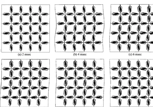
to design a lacing system so that its members are just strong enough to carry the shearing forces, which arise when a deflection reaches the magnitude at which the chord on the concave side of the bent plate begins to yield. The highest stressed parts of the grid will then yield or collapse simultaneously. The deformed shape is very similar to the test results, which are shown in Figure 8. The deformed shape in the elastic region tends to return to the original shape by strain localization. The elastic unloading phenomenon is shown well in this Figure. In Table 2, the analysis results are compared with the test results.
Table 2. Comparison between the test and analysis results
5.26 %
(a) 2 msec
ii I!i "~iil I¢ ...
J
t
(d) 8 msec
1
l
- -
i
(b) 4 msec
"i]il = ] i] ELii--'
; d
(c) 6 msec
(e) 10 msec (f) 12 msec
Fig. 8 Deformed shape at Vo = 0.36 m/sec from finite element analysis
S U M M A R Y C O N C L U S I O N
G
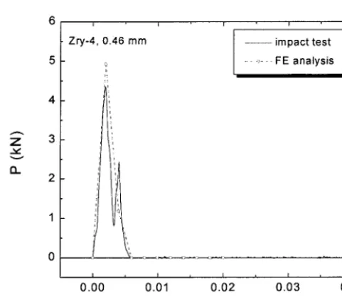
those of the impact test. The reason for local buckling is considered to be the strain localization of the plastic hinge, which is located in the vicinity of the welding nugget. If there is plastic deformation, the stiffness of the material at the plastic region should be locally much lower. The nonlinear dynamic impact analysis for the spacer grid is conducted and the intrinsic boundary condition of the grid structure is checked. The importance of the boundary conditions is apparently verified by using several boundary conditions. It seems that the difference is caused by the geometry of each specimen. Comparing the analysis results with the test results defines the boundary conditions finally applied. The analysis results correspond well with the test results and can predict the critical buckling strength and impact velocity as Figure 9. Therefore, this FE model and analysis procedure will be used as a tool for predicting the nonlinear buckling behavior of the grid structures. The drop test shows some of the grid's the interesting buckling. The deviation bounds of the impact force and acceleration by the test are within +4 % only. The buckling behavior of the 5x5 cell array grid structure by nonlinear dynamic impact analysis is in good agreement with the test result.
Z
v
Q.
i t
Z r y - 4 , 0 . 4 6 m m ~ i m p a c t t e s t
.~ ... F E a n a l y s i s
I , I I , I ,
0.00 0.01 0.02 0.03 0.04
t (sec)
Fig. 9 Comparison of the Impact Force Time-History between Impact Test and FE Analysis
ACKNOWLEDGEMENT
This project has been carried out under the nuclear R&D program by MOST.
REFERENCES
1. Song, K. N. et al., "Development Status and Research Directions on the Structural Components of the Fuel Assembly,"
KAERI Report, TR-865/97, 1997.
2. I-DEAS Master Series rM User's Manual, Version 7ml, Structural Dynamics Research Corporation, 1999. 3. ABAQUS User's Manual, Version 5.7, Hibbit, Karlsson & Sorenssen, Inc. 1998.
4. ASTM E8M-99, "Standard Test Methods for Tension Testing of Metallic Materials", 1999.