555-231-109
Comcode 108596974
Issue 1
April 2000
Issue 6
Every effort was made to ensure that the information in this book was complete and accurate at the time of printing. However, information is subject to change.
Your Responsibility for Your System’s Security
Toll fraud is the unauthorized use of your telecommunications system by an unauthorized party, for example, persons other than your com-pany’s employees, agents, subcontractors, or persons working on your company’s behalf. Note that there may be a risk of toll fraud associated with your telecommunications system and, if toll fraud occurs, it can result in substantial additional charges for your telecommunications services.
You and your system manager are responsible for the security of your system, such as programming and configuring your equipment to pre-vent unauthorized use. The system manager is also responsible for reading all installation, instruction, and system administration docu-ments provided with this product in order to fully understand the fea-tures that can introduce risk of toll fraud and the steps that can be taken to reduce that risk. Lucent Technologies does not warrant that this product is immune from or will prevent unauthorized use of com-mon-carrier telecommunication services or facilities accessed through or connected to it. Lucent Technologies will not be responsible for any charges that result from such unauthorized use.
Lucent Technologies Fraud Intervention
If you suspect that you are being victimized by toll fraud and you need technical support or assistance, call the BCS Technical Service Center Toll Fraud Intervention Hotline at 1-800-643-2353. Outside the conti-nental United States, contact your local Lucent Technologies autho-rized representative.
Federal Communications Commission Statement
Part 15: Class A Statement. This equipment has been tested and found to comply with the limits for a Class A digital device, pursuant to Part 15 of the FCC Rules. These limits are designed to provide reason-able protection against harmful interference when the equipment is operated in a commercial environment. This equipment generates, uses, and can radiate radio frequency energy and, if not installed and used in accordance with the instruction manual, may cause harmful interference to radio communications. Operation of this equipment in a residential area is likely to cause harmful interference, in which case the user will be required to correct the interference at his own expense. Part 68: Network Registration Number. This equipment is registered with the FCC in accordance with Part 68 of the FCC Rules. It is identi-fied by FCC registration number AS593M-13283-MF-E.
Canadian Department of Communications (DOC) Interference Information
This digital apparatus does not exceed the Class A limits for radio noise emissions set out in the radio interference regulations of the Canadian Department of Communications.
Le Présent Appareil Nomérique n’émet pas de bruits radioélectriques dépassant les limites applicables aux appareils numériques de la class A préscrites dans le reglement sur le brouillage radioélectrique édicté par le ministére des Communications du Canada.
Trademarks
AUDIX, DEFINITY, and GuestWorks are registered trademarks of Lucent Technologies.
Comsphere is a registered trademark of Paradyne Corp.
Xiox is a trademark of Xiox Corporation. Ordering Information
Call: Lucent Technologies Publications Center U.S. Voice: 1 888 582 3688
U.S. Fax: 1 800 566 9568 Canada Voice: +1 317 322 6619
Europe, Middle East, Africa Voice: +1 317 322 6416 Asia, China, Pacific Region, Caribbean,
Latin America Voice: +1 317 322 6411 Non-U.S. Fax: +1 317 322 6699 Write: Lucent Technologies Publications Center
2855 N. Franklin Road Indianapolis, IN 46219 U.S.A.
Order: Document No. 555-231-109 Comcode 108596974 1, April 2000
For more information about Lucent Technologies documents, refer to the section entitled “Related Documents” in “About This Handbook.” You can be placed on a Standing Order list for this and other BCS doc-uments you may need. Standing Order will enable you to automatically receive updated versions of individual documents or document sets, billed to account information that you provide. For more information on Standing Orders, or to be put on a list to receive future issues of this document, please contact the Lucent Technologies BCS Publications Center.
GuestWorks Support
To receive support on GuestWorks, call 1-800-242-2121. Outside the continental United States, contact your local Lucent Technologies authorized representative.
European Union Declaration of Conformity
The “CE” mark affixed to the equipment described in this book indi-cates that the equipment conforms to the following European Union (EU) Directives:
• Electromagnetic Compatibility (89/336/EEC) • Low Voltage (73/23/EEC)
• Telecommunications Terminal Equipment (TTE) i-CTR3 BRI and i-CTR4 PRI
For more information on standards compliance, contact your local dis-tributor.
Comments
To comment on this document, return the comment form. Lucent Technologies Web Page
The World Wide Web home page for Lucent Technologies is http://www.lucent.com
Acknowledgment
Contents
Contents iii
About This Handbook 1
■ Suggested Training 1
■ Reasons for Issue 1
■ Conventions 2
■ Related Documents 3
■ GuestWorks Features 6
Installing the System 9
■ Overview 9
■ Installation Checklist 10
■ Upgrade Issues 11
■ Additional Parts and Test Equipment 11 ■ Planning and Preparing the Site 12
■ Unpacking the Equipment 16
■ Installing and Connecting the Equipment 16 ■ Installing Telecommunications Cabling 17 ■ Installing the Management Terminal 17 Connecting a PC to the Switch 18
Parts List 18
Cabling Diagram 18
■ Activating the Systems 19
■ Setting Up the Initial Options 20 ■ Connecting the Hospitality Adjuncts 22 Overall GuestWorks Connectivity 24
Switch-to-INTUITY Admin Link (TCP/IP) 26
Parts List 26
Distance Limits 26
Cabling Diagram 27
Crossover Wiring 28
Switch-to-INTUITY Admin Link (X.25) 29
Parts List 29
Distance Limits 30
Switch-to-INTUITY Admin Link (Mode Code
Integration) 31
Switch-to-INTUITY Voice Port Connections 32
Parts List 32
Distance Limits 33
Cabling Diagram 36
INTUITY Lodging-to-PMS Link 37
Parts List 37
Distance Limits 37
Cabling Diagram 38
Test Procedure 39
Switch-to-Call Accounting Link (with
Co-Resident INTUITY Lodging Call Accounting) 41
Parts List 41
Distance Limits 41
Cabling Diagram 42
Test Procedure 42
Switch-to-Call Accounting Link (Xiox Call
Accounting System) 44
Parts List 44
Distance Limits 44
Cabling Diagram 45
Test Procedure 45
Switch-to-Call Accounting Link (Stand-alone Call
Accounting Systems) 47
Parts List 47
Distance Limits 47
Cabling Diagram 47
Test Procedure 48
Switch-to-Call Accounting Link using DCP
Data Modules 50
Parts List 50
Distance Limits 51
Cabling Diagram 51
8400B Options 52
7400A Options 53
INTUITY Lodging Call Accounting-to-PMS Link 55
Parts List 55
Distance Limits 55
Cabling Diagram 56
Xiox Call Accounting-to-PMS Link 57
Parts List 57
Distance Limits 57
Cabling Diagram 57
Switch-to-PMS Link 58
Parts List 58
Distance Limits 58
Cabling Diagram 59
8400B Options 60
7400A Options 61
7400B Options 62
Test Procedure 62
Journal/PMS Log or System Printer Connections
on the Switch 64
Parts List 64
Distance Limits 64
Cabling Diagram 65
8400B Options 66
7400A Options 67
7400B Options 68
Okidata Model ML321T Journal/PMS Log
Printer Options 69
Okidata Model ML321T System Printer Options 70
Test Procedure 72
Printer Connection on the INTUITY 74
Parts List 74
Cabling Diagram 74
Switch-to-INADS Connections 75
Parts List 75
SCC and MCC 75
CMC 75
INADS Registration 77
MAP Remote Access Connections 78
Parts List 78
Cabling Diagram 79
INADS Alarm Origination Download 80
Translations and Testing 81
■ Checklist 82
■ Miscellaneous Translations 83
Time of Day and Date (INTUITY) 84
Dial by Name Special Application (Switch) 85
Dial Plan (Switch) 86
Dial Plan (INTUITY) 87
Feature Access Codes (Switch) 88
Class of Service (Switch) 91
Class of Restriction (Switch) 93
Class of Service (INTUITY) 100
System Parameters (INTUITY) 101
Fax Parameters (Switch and INTUITY) 103
Billing Considerations When Forwarding Faxes 104
Abbreviated Dialing Lists (Switch) 105
Listed Directory Numbers (Switch) 106
Attendant Console (Switch) 107
Attendant Console Button Layouts (Switch) 108
Attendant Backup (Switch) 112
Office Staff, Front Desk, and Guest Services
Telephones (Switch) 114
Backup Telephone Button Layouts (Switch) 117
Mailboxes for AUDIX Subscribers (INTUITY) 120
Guest Room Telephones (Switch) 121
Administering Analog Caller ID (Switch) 124
Administering Caller ID 124
Administering Caller ID Station Options 125
Suite Telephones (Switch) 126
Enabling Suite Check-In 127
Administering Station Hunt Before Coverage 128
Considerations 129
Mailboxes for Guest Rooms (INTUITY) 131
Recorded Announcements (Switch) 132
Emergency Access to Attendant (Switch) 136
Crisis Alert (Switch) 137
Trunk Groups (Switch) 141
Automatic Selection of DID Numbers (Switch) 142
Enabling Automatic Selection of DID Numbers 143
Assigning the DID Numbers 143
Assigning a DID View Button 144
Considerations 144
Automatic Wakeup Options (Switch) 145
Call Vectoring (Switch) 146
Dial by Name (Switch) 148
Trunk-to-Trunk Transfer (Switch) 151
■ Switch-to-INTUITY Translations 152 Switch-to-INTUITY Messaging Link 152
TCP/IP Signaling 153
TCP/IP Link (Switch) 153
TCP/IP Link (INTUITY) 160
Testing the TCP/IP Link 164
X.25 Signaling 169
X.25 Link (Switch) 169
X.25 Link (INTUITY) 172
Testing the X.25 Link 174
Mode Code Signaling 176
Mode Code Integration Link (Switch) 176
Mode Code Integration (INTUITY) 177
INTUITY AUDIX Voice Ports (Switch) 178
Hunt Groups for INTUITY AUDIX
Voice Ports (Switch) 181
Extensions for Guest Message Retrieval (Switch) 183
Call Coverage Path (Switch) 184
INTUITY AUDIX Voice Ports (INTUITY) 185
Attendant and Administrator Passwords (INTUITY) 188
Testing the Switch-to-INTUITY Voice Ports 189
■ INTUITY Lodging-to-PMS Translations 190 PMS Interface for GuestWorks 191
Stand-alone Interface Link 193
Testing the INTUITY Lodging-to-PMS Link 196
■ Switch-to-Call Accounting Translations 200
Link Parameters (INTUITY) 200
CDR Parameters (Switch) 200
Testing the Switch-to-Call Accounting Link 201
■ INTUITY Lodging Call Accounting-to-PMS Translations 202 Testing the INTUITY Lodging Call
Accounting-to-PMS Link 202
■ Switch-to-PMS Link Translations 203 Network Control (Netcon) Data Module 203
Data Modules 204
Hospitality Parameters 204
Housekeeping Status 207
Controlled Restrictions 209
Testing the Switch-to-PMS Link 210
Switch-to-PMS Link Testing with the
RS232 Mini-Tester 211
Netcon and Data Module Testing 213
PMS Testing and Status 214
Database Swap Testing 215
Check-In and Check-Out Testing 216
Message Waiting Testing 217
Controlled Restrictions Testing 220
Housekeeping Status Testing 221
■ Journal/PMS Log and System Printer
Translations (Switch) 222
Testing the Journal/PMS Log or System Printer 225
■ Parallel Printer Translations (INTUITY) 227
■ Customer Logins (Switch) 227
■ Customer Logins (INTUITY) 227
■ Save Translations (Switch) 229
■ Create Backup (INTUITY) 229
Continuing with the Switch Installation 231
■ Testing the Switch 231
■ Installing and Wiring Telephones and Other Equipment 231 ■ Testing Telephones and Other Equipment 232
■ Customer Turnover 232
■ Maintenance 233
Appendixes 235
■ Appendix A — Parts List 236
■ Appendix B — Connector Pinouts 238 ■ Appendix C — List PMS Down Events 239 ■ Appendix D — Homisco Call Record Format 242 ■ Appendix E — Xiox Call Accounting
Posting Interface and Format 243
About This Handbook
This handbook provides instructions for installing the GuestWorks® switch and all
adjuncts offered as part of the GuestWorks Issue 6 solution. The information pro-vided in this handbook includes information about preparing the site, unpacking and installing the cabinets, connecting cabling and adjuncts, translating the switch and adjuncts, and activating and testing the switch.
Suggested Training
It is suggested that technicians installing this equipment receive training on
Guest-Works and the DEFINITY® Enterprise Communications Server (ECS) Release 8
(R8), before installing this equipment. Except for connectivity of hospitality adjuncts and translations of those adjuncts, this handbook contains high-level reminders of the tasks required to install the switch, and is not intended to replace normal switch training or standard switch installation documents.
Reasons for Issue
This document replaces the GuestWorks Issue 5 Technicians Handbook
(555-231-108) that is still valid on GuestWorks Issue 5 systems. This document supports GuestWorks Issue 6, and is issued for the following reasons:
■ To update all information related to Issue 6 of the GuestWorks product.
GuestWorks Issue 6 is based on the latest DEFINITY ECS R8 software.
■ To update information about the Transmission Control Protocol/Internet
Protocol (TCP/IP) messaging connectivity between the switch and the INTUITY™ voice messaging system.
■ To add information about the 7400B data module, which can be used in
place of the 7400A data module.
■ To add information about new features, including:
— Translation Copy Protection
— Analog Station Caller ID
— Suite Check-In
— Automatic Selection of Direct Inward Dialing (DID) Numbers
— Station Self-Display.
Conventions
The following conventions are used in this handbook:
■ The GuestWorks system can consist of the switch, the INTUITY platform
(usually the MAP/5P), and a Property Management System (PMS). In this handbook, the term “switch” refers to the telephone switching equipment, the term “INTUITY” refers to the voice messaging or call accounting plat-form, and the term “PMS” refers to the property management system pro-vided by the customer.
■ All screens shown in this handbook are approximations of how the actual
screens appear. Depending on the system options, the screens may vary.
■ The terms “attendant console” and “backup telephone” are used in this
document. The attendant console is the model 302B or 302C that is usually found at the front desk. The preferred backup telephone is the model 6424 or 8434 telephone with attendant-type feature buttons. The model 6408 or 8410 can be used as a secondary backup to the model 6424 or 8434.
■ For most GuestWorks installations, the MAP/5P is the voice messaging
platform of choice. For very large installations that require more voice ports or message storage, the MAP/40P or MAP/100 may be used. Unless other-wise noted, the term “MAP” refers to any of the different platforms. Any dif-ferences between the platforms (other than capacities) will be noted in this handbook.
■ With GuestWorks Issue 6, two versions of the INTUITY system will be
available — Release 4.4 (R4.4) and Release 5 (R5). Unless otherwise specified, all connectivity and administration applies to either release.
■ Administration command paths and options you enter in the administration
fields are shown as follows:
change system-parameters hospitality
Some administration command paths have additional actions available (such as change, list, add, and display). In this document, only the sug-gested action is shown in the administration sections.
■ Field names referring to the administration screens are shown as follows:
Queue Length
■ GuestWorks hardware is offered on the compact modular cabinet (CMC), the single-carrier cabinet (SCC), or the multi-carrier cabinet (MCC) plat-forms. Specific cabinet models will not be mentioned except when neces-sary. Refer to the installation document for the cabinet type you are installing.
■ Switch software is packaged for csi, si, or r systems. The csi system uses
CMC hardware, the si system uses SCC or MCC hardware, and the r
sys-tem uses MCC hardware.
Related Documents
The following documents will be useful when installing the GuestWorks system. Most of these documents are included on the Documentation Library CDs shipped with the system.
■ 555-015-201 — DEFINITY® Terminals and Adjuncts Reference
■ 555-020-706 — 7400A Data Module User Guide
■ 555-020-707 — 7400B Data Module User Guide
■ 555-020-709 — 8400B Plus Data Module User’s Guide
■ 555-025-600 — BCS Products Security Handbook
■ 555-230-700 — DEFINITY® ECS Release 8 Console Operations
■ 555-230-755 — GuideBuilder™ Software for DEFINITY® Telephones
■ 555-230-890 — DEFINITY® ECS Release 8 Console Operations Quick
Reference
■ 555-231-104 — GuestWorks® server Technician Connectivity Training
(video tape)
■ 555-231-205 — GuestWorks® server INTUITY™ Lodging Call Accounting
User’s Guide
■ 555-231-208 — DEFINITY® Business Communications System and
GuestWorks® Issue 6 Overview
■ 555-231-601 — DEFINITY® ECS and GuestWorks® Property Management
System Interface Specifications
■ 555-231-785 — DEFINITY® Business Communications System and
GuestWorks® Issue 6 Call Vectoring Guide
■ 555-233-114 — DEFINITY® ECS Release 8 Installation and Test for
Multi-Carrier Cabinets
■ 555-233-115 — DEFINITY® ECS Release 8 Upgrades and Additions for
■ 555-233-116 — DEFINITY® ECS Release 8 Installation for Adjuncts and Peripherals
■ 555-233-117 — DEFINITY® ECS Release 8 Maintenance for R8r
■ 555-233-118 — DEFINITY® ECS Release 8 Installation, Upgrades and
Additions for Compact Modular Cabinets
■ 555-233-119 — DEFINITY® ECS Release 8 Maintenance for R8csi
■ 555-233-120 — DEFINITY® ECS Release 8 Installation and Test for
Sin-gle-Carrier Cabinets
■ 555-233-122 — DEFINITY® ECS Release 8 Upgrades and Additions for
R8si
■ 555-233-123 — DEFINITY® ECS Release 8 Maintenance for R8si
■ 555-233-200 — DEFINITY® ECS Release 8 System Description
■ 555-233-411 — DEFINITY® ECS Release 8.1 Change Description
■ 555-233-506 — DEFINITY® ECS Release 8 Administrator’s Guide
■ 555-233-705 — Using the New Abbreviated Dialing Program Feature
■ 555-233-755 — GuestWorks® and DEFINITY® ECS Release 8 Hospitality
Operations
■ 555-233-756 — DEFINITY® System’s Little Instruction Book for Basic
Administration
■ 555-233-757 — DEFINITY® System’s Little Instruction Book for Advanced
Administration
■ 555-233-758 — DEFINITY® System’s Little Instruction Book for Basic
Diagnostics
■ 555-233-813 — DEFINITY® ECS Release 8 Documentation Library (CD)
■ 585-310-169 — INTUITY™ Messaging Solutions Release 4 MAP/40 and
MAP/40s System Installation
■ 585-310-170 — INTUITY™ Messaging Solutions Release 4 System
Installation Worksheets
■ 585-310-171 — INTUITY™ Messaging Solutions Release 4 MAP/40
Maintenance
■ 585-310-173 — INTUITY™ Messaging Solutions Release 4 MAP/100
System Installation
■ 585-310-174 — INTUITY™ Messaging Solutions Release 4 MAP/100
Maintenance
■ 585-310-185 — INTUITY™ Messaging Solutions Release 4 MAP/5P
■ 585-310-186 — INTUITY™ Messaging Solutions Release 4 MAP/5P Maintenance
■ 585-310-196 — INTUITY™ Messaging Solutions Release 4 MAP/40P
System Installation
■ 585-310-197 — INTUITY™ Messaging Solutions Release 4 MAP/40P
Maintenance
■ 585-310-234 — INTUITY™ Lodging Property Management Specifications
■ 585-310-257 — INTUITY™ Messaging Solutions Integration with
System 75, DEFINITY® Generics 1 & 3, and R5/6
■ 585-310-564 — INTUITY™ Messaging Solutions Release 4 Administration
■ 585-310-577 — INTUITY™ Lodging Release 4 Administration
■ 585-310-745 — GuideBuilder™ Software for AUDIX System
■ 585-313-401 — INTUITY™ Messaging Solutions Release 4 Supplement
for Technicians
■ 585-313-602 — INTUITY™ Messaging Solutions Release 4 Using a LAN
to Integrate with DEFINITY® ECS
■ 585-313-604 — INTUITY™ Messaging Solutions Release 5 Using a LAN
to Integrate with DEFINITY® ECS
■ 585-313-807 — INTUITY™ Messaging Solutions Release 5
GuestWorks Features
DEFINITY now allows different offer categories for customers. Offer Category A contains all possible DEFINITY features and is used by the DEFINITY ECS and ProLogix™ products. Offer Category B contains a subset of Offer Category A fea-tures used by the GuestWorks and DEFINITY Business Communications System (BCS) products. The following is an abbreviated list of the GuestWorks features most related to hospitality:
■ Analog Station Caller ID (new for Issue 6)
■ Answer Detection
■ ASCII Data Over the Switch-to-Property Management System (PMS) Link
■ Attendant Backup
■ Attendant Split Swap
■ Authorization Codes
■ Automated Attendant
■ Automatic Alternate Routing (AAR)
■ Automatic Route Selection (ARS)
■ Automatic Selection of DID Numbers (new for Issue 6)
■ Attendant-activated Automatic Wakeup Service
■ Attendant-activated Do Not Disturb
■ Basic Call Management System (BCMS)
■ Busy Verification
■ Call Vectoring (requires the TN750C circuit pack when using Call Vectoring
for the Automated Attendant feature)
■ Check-in/Check-out
■ Controlled Restrictions (the Toll Restriction option requires activation by
Lucent Technologies technical support)
■ Crisis Alert to attendant console, display station, or digital pager (alerting a
pager is new for Issue 6)
■ Daily Wakeup
■ Dial by Name (activation controlled by Lucent Technologies technical
sup-port)
■ Dual Wakeup
■ Emergency Access to the Attendant
■ Guest-activated Automatic Wakeup (requires a speech synthesizer circuit
■ Guest-activated Do Not Disturb (requires a speech synthesizer circuit pack)
■ Integrated Services Digital Network (ISDN) access using Primary Rate
Interface (PRI) and Basic Rate Interface (BRI) telephones and adjuncts
■ Maid Status
■ Message Waiting Lamps, either light-emitting diode (LED) or neon on guest
room telephones
■ Names Registration
■ PMS Interface
■ Recorded Announcements (requires the TN750C circuit pack)
■ Room Status
■ Station Self-Display (new for Issue 6)
■ Suite Check-In (new for Issue 6)
■ Switch/INTUITY/PMS Link Integration
NOTE:
If your installation is using the Mode Code Integration feature, the Switch/INTUITY/PMS Link Integration feature is not an option.
■ Terminal Translation Initialization
■ Trunk Identification
■ VIP Wakeup
■ Wakeup Activation via Tones
NOTE:
If Wakeup Activation via Tones is enabled, the wakeup feature provided by a Speech Synthesizer circuit pack is disabled from service.
Installing the System
This section describes the procedures you must use to install the components of a GuestWorks system.
Overview
Before you connect the switch to the hospitality adjuncts (see “Connecting the
Hospitality Adjuncts” on Page 22), you must first install the basic switch equipment and, if purchased, install the INTUITY voice messaging system. Use the following documents when installing the switch and voice messaging equipment:
■ DEFINITY ECS Release 8 Installation, Upgrades and Additions for
Com-pact Modular Cabinets
■ DEFINITY ECS Release 8 Installation and Test for Single-Carrier Cabinets
■ DEFINITY ECS Release 8 Installation and Test for Multi-Carrier Cabinets
■ DEFINITY ECS Release 8 Change Description
■ DEFINITY ECS Release 8 Installation for Adjuncts and Peripherals
■ INTUITY Messaging Solutions Release 4 MAP/5P System Installation
■ INTUITY Messaging Solutions Release 4 MAP/40P System Installation
■ INTUITY Messaging Solutions Release 4 MAP/40 and MAP/40s System
Installation
■ INTUITY Messaging Solutions Release 4 MAP/100 System Installation
Installation Checklist
The following is a brief checklist of the tasks required to install and translate a GuestWorks system.
Table 1. Installation Checklist
✔
Procedure
Begins
on...
Determine upgrade issues Page 11
Verify parts and test equipment Page 11
Plan and prepare the site Page 12
Unpack the equipment Page 16
Install and connect the equipment Page 16
Install telecommunications cabling Page 17
Install the management interface Page 17
Activate the systems Page 19
Set up the initial options Page 20
Connect and test the hospitality adjuncts Page 22
Miscellaneous translations and testing Page 83
Switch-to-INTUITY translations and testing Page 152
INTUITY Lodging-to-PMS translations and testing Page 190
Switch-to-Call Accounting translations and testing Page 200
INTUITY Lodging Call Accounting-to-PMS translations and testing
Page 202
Switch-to-PMS link translations and testing Page 203
Printer translations and testing Page 222
Logins, security, and backups Page 227
General switch testing Page 231
Install and wire telephones and other equipment Page 231
Test telephones and other equipment Page 232
Upgrade Issues
Upgrades are treated differently depending on the release the system is upgraded from.
If you are upgrading a GuestWorks Issue 1, 2, or 3 system to Issue 6, you must record all of the existing switch translations, perform the upgrade, and re-translate the switch. Adjunct translations may not have to change, but you should check them for accuracy. Contact your project manager for more information.
If you are upgrading a GuestWorks Issue 4 or Issue 5 system to Issue 6, certain preliminary translation work must be done before you can upgrade the switch. Contact your project manager to confirm that all upgrade issues have been resolved before you begin the upgrade. In many cases, you will not need to reinstall any of the cabling between the switch and the adjuncts. However, you will have to verify that the connections are still required. Similarly, you will not need to readminister all of the switch and adjunct translations, but you will have to verify that the translations are still accurate.
Additional Parts and Test Equipment
Other than the tools and test equipment noted in the installation manuals, you should also have the following items available on-site:
■ RS232 mini-tester (comcode 407515139)
NOTE:
The mini-tester shows positive voltage with a green LED and negative voltage with a red LED. This can be verified by connect-ing the mini-tester to a printer’s EIA port, addconnect-ing power to the printer, and then putting the printer on-line. The Data Terminal Ready (DTR) lamp should then light with a positive (green) volt-age. You may already have your own mini-tester that shows pos-itive voltage as red and negative voltage as green. If this is true at your installation, the mini-tester result diagrams shown in this handbook must be read from an “opposite” perspective; that is, if the book shows that DTR should be green, and you have a mini-tester that operates in an “opposite” mode, your mini-mini-tester will show DTR being red. This change in perspective should be true for all data leads.
!
CAUTION:
■ RS232 gender changers and M25A or M25B RS232 cables
■ Analog line used to place test calls.
See “Appendix A — Parts List” on Page 236 for a list of the parts used in this installation. Part numbers are provided if replacements must be ordered.
Planning and Preparing the Site
See Chapter 1 in the DEFINITY ECS and INTUITY installation documents for more information about the tasks in this section.
1. Inventory the equipment delivered to the customer site and verify that it
matches the customer’s order. If the equipment does not match the cus-tomer’s order, follow the appropriate claims process or report the discrep-ancies to your Lucent Technologies representative. If this is a dealer-installed site, report the discrepancies to the dealer.
The equipment may include the following:
■ Switch cabinets and circuit packs
!
DANGER:
Check your system for TN793 and TN2793 analog line circuit packs. If the TN793 is vintage 5 or earlier, or if the TN2793 is vin-tage 3 or earlier, do not use these circuit packs with telephones requiring neon message waiting lamps. Request a remediation update for those circuit packs. Contact your Lucent representa-tive and request information about replacing these older circuit packs via QPPCN 1126D (TN793) and QPPCN 1127B (TN2793).
■ Default translation card
Unless instructed otherwise, always use the default translation card.
!
CAUTION:
■ DEFINITY Site Administration (DSA) software for a PC, or a 715 management terminal
■ Multi-Application Platform (MAP) for INTUITY Lodging Voice
Mes-saging, INTUITY AUDIX Voice MesMes-saging, and INTUITY Lodging Call Accounting
When using the INTUITY Lodging Call Accounting from Homisco,
share “Appendix D — Homisco Call Record Format” on Page 242
with the PMS vendor before or during the switch integration.
■ Xiox™ call accounting equipment, which will be software, a buffer
box, and a PC
Call Xiox technical support at +1-480-970-9015, +1-602-970-9015, +1-603-624-4424, or +1-650-548-5200 if any issues arise about their call accounting equipment or installation support.
■ Attendant console (Model 302B or 302C)
■ Multiappearance telephones (usually the 6400-series
or 8400-series; a 6424 or 8434 is recommended as the primary attendant backup telephone)
■ Guest room telephones
If custom room telephones and faceplates are being ordered, coor-dinate the translations on the switch with any special feature access buttons being programmed by the vendor. If programming is done ahead of time, this could save time at installation.
■ Modems
■ Printers
The Okidata® Models 320 and 321 are often used for GuestWorks,
but be aware that other printers may be delivered on site.
■ Customer documentation
■ Miscellaneous equipment.
NOTE:
If the INTUITY Lodging Call Accounting co-resident application from Homisco has been ordered, part of the miscellaneous equipment is a set of adapters, cables, and user documentation used with the INTUITY system. This equipment is packaged in a separate box with the INTUITY equipment and is labeled “Hold for Homisco Technicians - Do Not Discard!” Save this equipment for the Homisco technicians.
2. Locate the equipment room and lay out the equipment room floor plan. If
possible, use standard floor plans as described in DEFINITY ECS
Release 8 System Description. When laying out the equipment locations, consider the following:
■ The switch-to-MAP link distance limitations depend on whether you
are using Transmission Control Protocol/Internet Protocol (TCP/IP), X.25, or Mode Code signaling:
— The TCP/IP link using the crossover cord is 328 feet (100 meters). This is the default configuration for GuestWorks.
— The TCP/IP link using a 10base-T hub or router is 656 feet (200 meters). This can be 328 feet (100 meters) on either side of the hub or router.
— The Isolating Data Interface (IDI) X.25 link must be 200 feet (61 meters) or less. This link is used only on upgrades to
Issue 6 when TCP/IP is not used. Duplicated si systems must
use data modules instead of IDI, so the distance limit is not an issue.
— The Mode Code link is done over the same analog voice ports connected between the switch and the voice messaging adjunct. The analog ports have a distance limit of 20000 feet (6100 meters). This connection is limited to upgraded sys-tems; the default configuration for Issue 6 is TCP/IP.
■ The link between the switch and the INTUITY Lodging Call
Account-ing on the MAP is limited to 50 feet (15.2 meters) unless you use DCP data modules to extend the distance. When using a
stand-alone call accounting system, there is still the 50 foot (15.2 meter) limit that can be extended with DCP data modules.
■ For the call accounting link, the MAP hardware must be within 50
Figure 2 on Page 24 illustrates an overall view of the GuestWorks connec-tions.
Additional equipment that you must consider when laying out the floor plan include the following:
— A customer-provided PC with DSA, or a 715 management terminal
— Cross-connect fields
— Space requirements and room layout
— Cable slack manager.
3. Lay out and ensure appropriate power for the switch and the management
terminal in the equipment room, and arrange for an electrician to install.
4. Lay out and ensure appropriate grounding in the equipment room,
includ-ing provisions for a coupled bondinclud-ing conductor (CBC).
5. Determine the location of equipment closets where feeder cables can be
terminated.
6. Determine where external trunk lines come into the building and where
external trunk converters and adapters will be installed.
7. Determine an appropriate available port circuit on the switch for each
tele-phone, trunk, and peripheral connection needed and create a provisioning plan based on standard procedures.
8. Have the customer contact the PMS vendor and, if not using the INTUITY
Lodging Call Accounting, the call accounting system vendor to find out if there are any special connections required to interface with their equip-ment. It is highly recommended that the customer schedule the vendors to be on-site when the connections are made and the testing is done for the PMS and the call accounting. If the vendors cannot be on-site, they should at least be available by telephone.
9. If this is an upgrade from an existing system, remind the customer that
Unpacking the Equipment
!
CAUTION:
Lifting and moving the switch cabinets may require two people. The average weight of a CMC is 50 pounds (23 kilograms), an SCC is 125 pounds (60 kilograms), and the MCC is 800 pounds (268 kilograms). Use caution to avoid injury.
See Chapter 1 in the DEFINITY ECS installation documents and Chapter 2 in the INTUITY installation documents for more information about the tasks in this sec-tion.
1. Unpack the equipment.
2. Inspect the equipment for any damage. Report any damages according to
local procedures.
3. Ensure that all circuit packs are fully inserted into the proper slots
accord-ing to the Customer Service Document (CSD). Report any discrepancies to your Lucent Technologies representative or authorized dealer.
Installing and Connecting the
Equipment
See the appropriate installation document for information about installing and con-necting the equipment:
■ For CMC installations, see Chapter 1 of DEFINITY ECS Release 8
Installa-tion, Upgrades and Additions for Compact Modular Cabinets.
■ For SCC installations, see Chapter 1 of DEFINITY ECS Release 8
Installa-tion and Test for Single-Carrier Cabinets.
■ For MCC installations, see Chapter 1 of DEFINITY ECS Release 8
Installa-tion and Test for Multi-Carrier Cabinets.
■ For installations with an INTUITY system, see Chapters 2 through 4 in the
Installing Telecommunications
Cabling
See the appropriate installation document for information about installing telecom-munications cabling:
■ For CMC installations, see Chapter 1 of DEFINITY ECS Release 8
Installa-tion, Upgrades and Additions for Compact Modular Cabinets.
■ For SCC installations, see Chapter 2 of DEFINITY ECS Release 8
Installa-tion and Test for Single-Carrier Cabinets.
■ For MCC installations, see Chapter 2 of DEFINITY ECS Release 8
Installa-tion and Test for Multi-Carrier Cabinets.
Installing the Management Terminal
The management terminal for administration on either the switch or the INTUITY system can be either a PC loaded with the DSA software or a dedicated manage-ment terminal (must be purchased separately). The customer is supposed to set up his or her customer-provided PC with DSA, but the technicians are responsible for connecting and setting up the 715 management terminal if it was purchased for the system. Use the customer’s PC or your own laptop PC to access the switch for administration during the installation.
See the appropriate installation document for information about installing the management terminal:
■ For CMC installations, see Chapter 1 of DEFINITY ECS Release 8
Installa-tion, Upgrades and Additions for Compact Modular Cabinets.
■ For SCC installations, see Chapter 3 of DEFINITY ECS Release 8
Installa-tion and Test for Single-Carrier Cabinets.
■ For MCC installations, see Chapter 3 of DEFINITY ECS Release 8
Installa-tion and Test for Multi-Carrier Cabinets.
■ For installations with an INTUITY system, see Chapter 4 in the INTUITY
installation documents.
Connecting a PC to the Switch
Use the on-line help for DSA to set the communication options on the PC.
Parts List
■ PC with keyboard and monitor
■ One M25A or M25B RS232 cable (or equivalent 25-pin straight-through
cable); see “Appendix A — Parts List” on Page 236
■ One 9-pin to 25-pin transition cable (if using a 9-pin COM port)
(comcode 847106945)
■ Gender changers, as needed.
Cabling Diagram
Activating the Systems
See the appropriate installation document for information about activating the switch and the INTUITY system:
■ For CMC installations, see Chapter 1 of DEFINITY ECS Release 8
Installa-tion, Upgrades and Additions for Compact Modular Cabinets.
■ For SCC installations, see Chapter 3 of DEFINITY ECS Release 8
Installa-tion and Test for Single-Carrier Cabinets.
■ For MCC installations, see Chapter 3 of DEFINITY ECS Release 8
Installa-tion and Test for Multi-Carrier Cabinets.
■ For installations with an INTUITY system, see Chapter 4 in the INTUITY
installation documents.
Unless instructed otherwise, always activate your system using the default
translation card.
!
CAUTION:
Setting Up the Initial Options
After activating the systems, there are some initial administration options you must set up. In addition to the procedures given in this section, see the appropriate installation document for information about setting up the initial options:
■ For CMC installations, see Chapter 1 of DEFINITY ECS Release 8
Installa-tion, Upgrades and Additions for Compact Modular Cabinets.
■ For SCC installations, see Chapter 3 of DEFINITY ECS Release 8
Installa-tion and Test for Single-Carrier Cabinets.
■ For MCC installations, see Chapter 3 of DEFINITY ECS Release 8
Installa-tion and Test for Multi-Carrier Cabinets.
■ For installations with an INTUITY system, see Chapter 5 in the INTUITY
installation documents.
NOTE:
Before setting any options, ensure that the default translation card is being used.
Do the following to set up the initial options:
1. After the switch powers up, log on to the switch using the craft login ID
and the crftpw password. Distributors should use the dadmin login ID.
2. Before you do any administration, verify that the default translation card is
activated for Offer Category B (GuestWorks and DEFINITY BCS offers). Check this by using the display system-parameters offer-options com-mand.
NOTE:
If the Offer Category is not set to B and activated, contact the technical support group or your regional Center of Excellence (COE). The switch must be set to Offer Category B, the transla-tions must be saved, and the switch must be reset before you can do any translations.
3. Set the required country options using the change system-parameters
country-options command.
4. Set the daylight savings time rules using the change
daylight-savings-rules command.
5. Set the date and the time using the set time command. This includes
6. Set the switch maintenance parameters using the change
system-param-eters maintenance command. For csi systems that have a C-LAN (TN799B) circuit pack, use Page 2 of this screen to verify that the Bus Bridge Packet Interface 2 has been enabled for the C-LAN circuit pack. If it is not already assigned, enter the C-LAN circuit pack equipment location, and use the defaults for the Timeslot Port fields as shown below.
7. Verify that the hospitality customer options have been enabled by checking
the display system-parameters customer-options screen. On Page 3, the following options must be enabled:
■ Hospitality (Basic)
■ Hospitality (G3V3 Enhancements)
These options can be enabled only with the init login ID. Contact technical
support or your COE if you do not have permission to make this change.
8. Change the craft password using the change password craft command.
!
CAUTION:
After the craft password is changed, the new password must be safeguarded to prevent unauthorized administration changes. This password MUST NOT BE REVEALED to the customer.
9. Save these initial translations. Use the save translation command. Label
the translation card with the current date and switch name.
!
CAUTION:
It is recommended that you save your translations regularly dur-ing the installation process. If a power failure occurs, all transla-tions since the last save are lost and must be readministered.
change system-parameter maintenance Page 2 of 3
MAINTENANCE-RELATED SYSTEM PARAMETERS
MINIMUM MAINTENANCE THRESHOLDS ( Before Notification ) TTRs: 4 CPTRs: 1 Call Classifier Ports:
MMIs: 0 VCs:
TERMINATING TRUNK TRANSMISSION TEST (Extension)
Test Type 100: Test Type 102: Test Type 105:
ISDN MAINTENANCE
ISDN-PRI TEST CALL Extension: ISDN BRI Service SPID:
DS1 MAINTENANCE
DSO Loop-Around Test Call Extension:
SPE OPTIONAL BOARDS
Packet Intf1? y Packet Intf2? y
Connecting the Hospitality Adjuncts
The hospitality adjuncts include the following:
■ INTUITY Lodging Voice Messaging
INTUITY Lodging Voice Messaging is an optional adjunct that resides on the MAP. INTUITY Lodging is used for the guest access to voice sages, and INTUITY AUDIX is used for the office staff to access voice mes-saging.
■ INTUITY Lodging Call Accounting
INTUITY Lodging Call Accounting is a co-resident application from Homisco that resides on the MAP. It is based on a product from the Homisco Corporation. At most installations, you can expect a technician from Homisco to be on site to install the software and hardware for the call accounting portion of the product. The Homisco technician will assist you in making the call accounting system interface to the switch.
For installations that include INTUITY Lodging Voice Messaging and INTU-ITY Lodging Call Accounting, all connections are shown in complete detail.
■ Stand-alone Call Accounting
Stand-alone call accounting systems (such as Xiox) can be installed if the call record format is compatible with GuestWorks. Two typical formats are
printer and Teleseer.
For installations that include voice mail or call accounting from another ven-dor, the connections are shown up to a definable demarcation point. Con-nections beyond that demarcation point must be coordinated with the vendor.
■ Property Management System (PMS)
The PMS is a vendor-provided product that interfaces to GuestWorks
according to the DEFINITY ECS and GuestWorks Property Management
■ Printers
Two serial printers can be installed to print hospitality reports and keep a log of events as they occur on the switch. Each printer connects to the switch using a DCP data module. The printers are designated as either a “journal/schedule” printer or a “log” printer. The journal/schedule printer records Emergency Access to Attendant calls and Automatic Wakeup calls. The log printer records housekeeping updates when the PMS link is down, in addition to recording any other PMS-related events. These PMS events
are shown in “Appendix C — List PMS Down Events” on Page 239.
NOTE:
In most cases, only one printer is provided to perform both the journal/schedule and log printer functions.
Overall GuestWorks Connectivity
Figure 2 shows the overall connectivity for GuestWorks when using the MAP for INTUITY Lodging Voice Messaging, INTUITY Lodging Call Accounting, plus connections to a PMS. References to the detailed connectivity drawings are
shown in this figure. Table 2 also gives references to the detailed connectivity
drawings based on the equipment you are installing.
Table 2. Matrix for Cabling Diagrams
In Figure 2, there are a variety of digital line circuit packs and telephones/data
modules that can be used. Table 3 shows which circuit packs should be used to
support the different digital telephones and data modules.
From... To... Switch INTUITY Lodging Voice Messaging INTUITY Voice Ports INTUITY Lodging Call Accounting Xiox Call Accountin g Stand-alone Call Accounting PMS
Switch Figure 3,
Figure 4,
Figure 6, or
Figure 9
Figure 9 Figure 11
or Figure 14 Figure 12 or Figure 14 Figure 13 or Figure 14 Figure 17 INTUITY Lodging Voice Messaging
Figure 3,
Figure 4,
Figure 6, or
Figure 9
Figure 10*
INTUITY Lodging Call Accounting Figure 11 or Figure 14 Figure 15 Xiox Call Accounting Figure 12 or Figure 14 Figure 16 Stand-alone Call Accounting Figure 13 or Figure 14 Designed Locally
* This connection is not required when using the Switch/INTUITY/Link Integration feature.
Table 3. Digital Line Circuit Packs and Telephone Equipment Compatibility
Equipment Circuit Packs TN754C (4-wire) TN2181 (2-wire) TN2214 (2-wire) TN2224 (2-wire)
302B Console (2-wire/4-wire) Yes Yes Yes Yes
302C Console (2-wire/4-wire) Yes Yes Yes Yes
6400-Series telephones (2-wire) No Yes Yes Yes
7400-Series telephones/data modules (4-wire)
Yes No No No
8400-Series telephones/data modules (2-wire/4-wire)
Switch-to-INTUITY Admin Link (TCP/IP)
This data link transfers information to support the INTUITY AUDIX service for office staff voice messaging. For all new installations, this is the recommended way to connect the switch to the MAP for voice messaging administrative mes-sages. If the system is an upgrade, you may reuse the X.25 hardware for this
con-nection; see “Switch-to-INTUITY Admin Link (X.25)” on Page 29. For installations
using Mode Code integration, see “Switch-to-INTUITY Admin Link (Mode Code
Integration)” on Page 31.
Parts List
■ An ethernet port on the C-LAN circuit pack (TN799B)
■ One 356A adapter (comcode 104158829), or
UTP Category 5 cross-connect hardware and connecting blocks
■ One 6-inch RJ45 crossover cord (comcode 846943306 or 104154414), or
One 10Base-T LAN hub or customer router (optional)
■ One or two RJ45 UTP Category 5 modular cords (see “Appendix A —
Parts List” on Page 236)
■ One or more 451A in-line RJ45 adapters, as needed (used to connect
modular cords together)
■ One LAN card on the MAP (for INTUITY R4.4, model 8412; for INTUITY
R5, model 8416).
Distance Limits
Using the standard crossover cord (or alternate crossover wiring arrangement in Figure 5), the distance limit between the switch and the MAP is 328 feet (100 meters).
Using a hub or customer router, the distance limit between the switch and the MAP is 656 feet (200 meters) total (328 feet [100 meters] from the switch to the hub or router, and 328 feet [100 meters] from the hub or router to the MAP). If the distance between the switch and the MAP is more than 656 feet (200 meters), you can daisy-chain up to four separate hubs.
NOTE:
If you do locate the switch more than 50 feet (15.2 meters) from the MAP and are using the coresident INTUITY Lodging Call Accounting system on the MAP, the call accounting link limit of 50 feet (15.2 meters) must be taken
into account. Figure 14 shows how the call accounting link can be extended
Cabling Diagram
Figure 3 shows a detailed connection between the C-LAN circuit pack and the LAN card on the MAP when using the default crossover cord.
Figure 3. Switch-to-INTUITY Admin Link (TCP/IP) with Crossover Cord
Figure 4 shows a detailed connection between the C-LAN circuit pack and the LAN card on the MAP when using the optional hub or customer router.
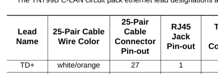
The TN799B C-LAN circuit pack ethernet lead designations are as follows:
Use this information when making connections from the TN799B using a 356A adapter (8-port harmonica), a 259A adapter (single-port), a 258B adapter (6-port harmonica), or standard cross-connect wiring. When using the 356A or 258B adapters, you must always connect to jack #1 of the adapter.
Crossover Wiring
If the standard crossover cord or the optional hub/router are not available, you can build your own crossover wiring arrangement to flip the transmit and receive leads
for the LAN connection. Figure 5 shows how this can be done with a 104A
con-necting block (comcode 105164859). When using this device, the distance limit from the switch to the INTUITY system is 328 feet (100 meters). Using this device, you would connect one Category 5 modular cord to the switch C-LAN circuit pack, and another Category 5 modular cord to the INTUITY LAN card.
Figure 5. Alternate Crossover Wiring
Lead
Name
25-Pair Cable
Wire Color
25-Pair
Cable
Connector
Pin-out
RJ45
Jack
Pin-out
Terminal Block
Pin-out on
Connecting Block
TD+ white/orange 27 1 3
TD- orange/white 2 2 4
RD+ white/green 28 3 5
Switch-to-INTUITY Admin Link (X.25)
This data link transfers information to support the INTUITY AUDIX service for office staff voice messaging. This connection will be used only if:
■ Your system has been upgraded from an Issue 4 or earlier system to
Issue 5 or later, and
■ The customer chooses to retain their X.25 hardware (a PI circuit pack is
needed on the si system, or a Packet Gateway circuit pack is needed on an
r system) instead of the TCP/IP C-LAN hardware.
See “Switch-to-INTUITY Admin Link (TCP/IP)” on Page 26. For installations using
Mode Code integration, see “Switch-to-INTUITY Admin Link (Mode Code
Integration)” on Page 31.
NOTE:
The connectivity shown in this section will not work on an si system with
duplication. For a duplicated system, the connection between the switch and the INTUITY is done with DCP data modules. See your project man-ager for more information.
Parts List
■ A PI port (TN765) on an si system, or a Packet Gateway port (TN577) on
an r system
■ One H600-347 cable (r system only)
■ One H600-210 Group 3 cable (50 feet; 15.2 meters)
■ One 105C IDI (comcode 107422735) or 105D IDI (comcode 108367376)
An IDI provides electrical isolation and protection between the switch and the INTUITY hardware. The dip switch settings on the IDI must be set for “Direct Connect.”
■ One ED1E434-11 Group 175 cable (4.5 feet; 1.5 meters)
■ One DCIU card (comcode 406801647, J1P260AA, L31) installed in the
Distance Limits
The distance limit between the switch and the IDI is 200 feet (61 meters). If you need a cable longer than the default 50 foot (15.2 meter) cable provided, order a Group 4 cable (100 feet; 30.5 meters) or a Group 5 cable (200 feet; 61 meters). See “Appendix A — Parts List” on Page 236 for a list of cables.
NOTE:
If you locate the switch more than 50 feet (15.2 meters) from the MAP and are using the coresident INTUITY Lodging Call Accounting system on the MAP, the call accounting link limit of 50 feet (15.2 meters) must be taken
into account. Figure 14 shows how the call accounting link can be extended
beyond this limit.
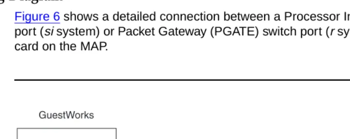
Cabling Diagram
Figure 6 shows a detailed connection between a Processor Interface (PI) switch
port (si system) or Packet Gateway (PGATE) switch port (r system) and the DCIU
card on the MAP.
Switch-to-INTUITY Admin Link (Mode Code
Integration)
When using Mode Code Integration, the administrative link between the switch and the MAP (the link that transfers information to support the INTUITY AUDIX service for office staff voice messaging) connects by way of an analog port on the switch and a voice port on the MAP. This connection is the same as the voice port
connections shown in “Switch-to-INTUITY Voice Port Connections” on Page 32
and Figure 9.
In other words, the voice ports used for leaving and retrieving messages on the INTUITY system are the same voice ports used for Mode Code Integration. This means that the ports will be in use for the amount of time it takes to leave a message plus the amount of time it takes for the Mode Codes to exchange messages between the switch and INTUITY. This will affect the traffic-handling of the voice messaging system.
Mode Code Integration should not be used if TCP/IP or X.25 link integration is
available. See “Switch-to-INTUITY Admin Link (TCP/IP)” on Page 26 or
“Switch-to-INTUITY Admin Link (X.25)” on Page 29 for more information.
NOTE:
When using Mode Code Integration, you cannot take advantage of the Switch/INTUITY/PMS Link Integration feature. This means that you must
install the link shown in “INTUITY Lodging-to-PMS Link” on Page 37.
Mode Code Integration between the switch and the MAP is described in more detail in the following documents:
■ DEFINITY® Release 8 Administrator’s Guide
■ INTUITY™ Messaging Solutions Release 4 MAP/5P System Installation
■ INTUITY™ Messaging Solutions Integration with System 75, DEFINITY® Generics 1 & 3, and R5/6
Switch-to-INTUITY Voice Port Connections
This connection is used for the following:
■ For callers leaving messages for guests and office staff
■ For guests and office staff to call the INTUITY system to retrieve their voice
messages
■ For the administrative link between the switch and the MAP when using
Mode Code Integration (see Page 31).
Parts List
■ One or more Tip/Ring cards in the MAP (different cards are required within
different regions of the world)
— IVC6 (AYC-10) Analog Voice Card (comcode 106406580)
— IVC6A (AYC-29) Tip/Ring Card (comcode 107213944)
— NGTR (AYC-30) Next Generation Tip/Ring Card (comcode 107224586)
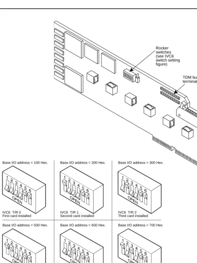
Each Tip/Ring card supports six voice ports. You can have up to three Tip/ Ring cards to support 18 ports for voice messaging. If your system came from the factory configured with more than one tip/ring card, the option set-tings on the cards should be set correctly. However, if you are adding a
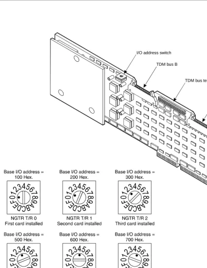
card on-site, or if you want to check the card configuration, Figure 7 shows
the switch settings for the IVC6 (AYC-10) and IVC6A (AYC-29) cards, and Figure 8 shows the switch settings for the NGTR (AYC-30) card.
If you have 18 voice ports, you must install three 885A connector kits. Figure 9 shows connections for one kit using all six voice ports. Depending on the customer’s order, you will install voice ports in pairs up to 18 ports.
■ Two or more ED5P208-30 Group 16 modular cords
You need two cords for each Tip/Ring card.
■ One 885A connector kit for each Tip/Ring card installed in the MAP
(ED-5P907-70, Group 1, comcode 601419666)
These kits come with one 885A connecting block (comcode 106079270), six RJ11C 4-wire modular cords (comcode 103732582), and two
RJ25 6-wire modular cords.
!
CAUTION:
Use the 885A connecting block label to record the extension numbers of the voice ports connected to the MAP.
■ Ferrites (one for each voice line) (comcode 407616846)
Ferrites are required for installation in some countries. See INTUITY
Mes-saging Solution Release 4 Supplement for Technicians for more informa-tion.
■ 103A modular connecting blocks (one for each voice port)
(comcode 105164818)
■ Standard cross-connect hardware
■ Ports on an analog circuit pack.
!
DANGER:
Check your system for TN793 and TN2793 analog line circuit packs. If the TN793 is vintage 5 or earlier, or if the TN2793 is vin-tage 3 or earlier, do not use these circuit packs with telephones requiring neon message waiting lamps. Request a remediation update for those circuit packs. Contact your Lucent representa-tive and request information about replacing these older circuit packs via QPPCN 1126D (TN793) and QPPCN 1127B (TN2793).
Each analog circuit pack supports 8, 16, or 24 analog voice connections. Depending on the circuit pack and the required number of voice ports, you may need to spread out the voice port assignments over more than one cir-cuit pack. For example, if you are using a 16-port circir-cuit pack, use no more than four ports of circuits 1-8 and four ports of circuits 9-16 on that circuit pack. If you still need more INTUITY voice ports, select a circuit pack that is at least one-quarter carrier distance away from the first circuit pack. For example, if your system has 12 voice ports and you assign the first eight ports to the circuit pack in slot 3, assign the other four voice ports to a cir-cuit pack in slot 7 or higher. See more about circir-cuit pack characteristics in the DEFINITY ECS Release 8 System Description.
Distance Limits
Figure 7. IVC6 and IVC6A Tip/Ring Card Switch Settings
8-pin modular jacks
Audio input
Audio output TDM bus
terminator SIPs Rocker
switches (see IVC6 switch setting figure)
Base I/O address = 100 Hex.
IVC6 T/R 0 First card installed
Base I/O address = 200 Hex.
IVC6 T/R 1 Second card installed
Base I/O address = 300 Hex.
IVC6 T/R 2 Third card installed
Base I/O address = 500 Hex.
IVC6 T/R 3 Fourth card installed
Base I/O address = 600 Hex.
IVC6 T/R 4 Fifth card installed
Base I/O address = 700 Hex.
IVC6 T/R 5 Sixth card installed
Base I/O address = 900 Hex.
IVC6 T/R 6 Seventh card installed
Figure 8. NGTR Tip/Ring Card Switch Settings
ngtr KLC 070296
I/O address switch
TDM bus B
TDM bus A TDM bus terminator SIPs
8-pin modular jacks
Cabling Diagram
Figure 9 shows the connections between analog circuit pack ports on the switch and a Tip/Ring card on the MAP.
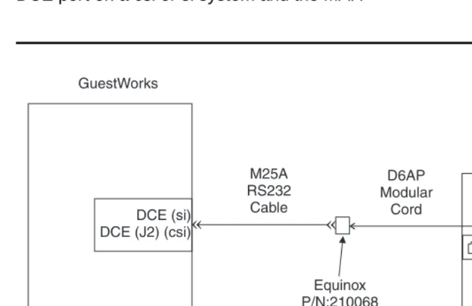
INTUITY Lodging-to-PMS Link
This connection is used to activate and deactivate guest voice messaging mail-boxes when guests check-in and check-out.
NOTE:
If the Switch/INTUITY/PMS Link Integration feature is used, this connection
is not required. See “INTUITY Lodging-to-PMS Translations” on Page 190
for more information about this feature. If Mode Code Integration is used, this link is required and cannot be removed.
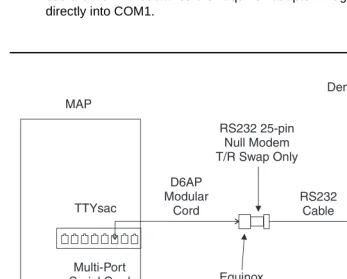
Parts List
■ One Multi-Port Serial card on the MAP (comcode 407009406; J1P260AA1,
List 12)
For this connection, use the third port on the card. This port is not marked on the card, but is administered in software as port TTYsac.
■ One D6AP modular cord (comcode 102937604)
■ One Equinox P/N:210068 DTE 10/10 adapter (DB25 DTE,
comcode 406983155); see “Appendix B — Connector Pinouts”
■ One null modem with transmit/receive swapped (all other leads are
straight-through) (comcode 407122043)
■ One RS232 cable (use gender changers as needed).
Distance Limits
Cabling Diagram
Figure 10 shows the connection used for controlling guest mailboxes between the MAP and the PMS.
NOTE:
For some installations, this connection at the MAP is made to COM1 instead of the Multi-Port Serial Card. If this is the case at your site, do not use the D6AP modular cord or Equinox adapter. Plug the Null Modem directly into COM1.
Figure 10. INTUITY Lodging-to-PMS Link
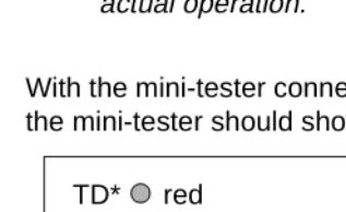
Test Procedure
Using the RS232 Mini-Tester (see the Note on Page 11), check the status of the
link where the Equinox adapter connects to the null modem as shown in
Figure 10. The leads marked with an asterisk are controlled by the INTUITY sys-tem, and the PMS controls the other leads. Translations for this connection begin on Page 190.
!
CAUTION:
After using a mini-tester to check data leads, you MUST remove the mini-tester from the connection. DO NOT leave the mini-tester in-line during actual operation.
With the mini-tester connected to only the Equinox adapter coming from the MAP, the mini-tester should show the following:
With the mini-tester connected to only the PMS at the null modem, the mini-tester should show the following:
TD*
RTS*
DTR* RD
CTS DSR
CD
dark
dark
green dark red
dark
dark
TD*
RTS*
DTR* RD
CTS DSR
CD
dark
red
dark red dark
red
With the mini-tester connected to the MAP and the PMS, but in an idle state, the mini-tester should show the following:
TD*
RTS*
DTR* RD
CTS DSR
CD
dark
red
green red red
red
Switch-to-Call Accounting Link (with
Co-Resident INTUITY Lodging Call Accounting)
This connection is used to transfer Call Detail Recording (CDR) information to the co-resident INTUITY Lodging Call Accounting software (Homisco). This connec-tion is valid for a csi or si system.
Parts List
■ The DCE port on the switch (this port is found on the Processor Interface
Cable of a csi system labeled as J2)
■ One M25A RS232 cable (or equivalent straight-through cable)
(comcode 105193668)
■ One Equinox P/N:210068 DTE 10/10 adapter (DB25 DTE,
comcode 406983155); see “Appendix B — Connector Pinouts”
■ One D6AP modular cord (comcode 102937604)
■ One Multi-Port Serial card on the MAP (comcode 407009406; J1P260AA1,
List 12).
For this connection, use the first port on the card. This port is not marked on the card, but is administered in software as port TTYsaa.
Distance Limits
The distance limit from the switch to the MAP is 50 feet (15.2 meters). If the dis-tance from the switch and the MAP is more than 50 feet (15.2 meters), or if the
switch is an r system, see “Switch-to-Call Accounting Link using DCP Data
Cabling Diagram
Figure 11 shows the connection used to transfer CDR information between the
DCE port on a csi or si system and the MAP.
Figure 11. Switch-to-Call Accounting Link (with Co-Resident INTUITY Lodging Call Accounting)
Test Procedure
Using the RS232 Mini-Tester (see the Note on Page 11), check the status of the
link where the Equinox adapter connects to the M25A cable as shown in
Figure 11. The leads marked with an asterisk are controlled by the switch, and the INTUITY Lodging Call Accounting system controls the other leads. Translations
for this begin on Page 200.
!
CAUTION:
With the mini-tester connected to only the M25A cable, the mini-tester should show the following:
With the mini-tester connected to only the Equinox adapter, the mini-tester should show the following:
With the mini-tester connected to the M25A cable and the Equinox adapter, the mini-tester should show the following (if any of the switch leads are dark on an end-to-end connection, the processor circuit pack should be replaced):
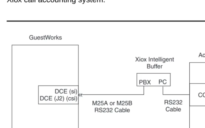
Switch-to-Call Accounting Link (Xiox Call
Accounting System)
This connection is used to transfer CDR information to the Xiox call accounting system. This connection is valid for a csi or si system.
Parts List
■ The DCE port on the switch (this port is found on the Processor Interface
Cable of a csi system labeled as J2)
■ One M25A or M25B cable plus gender changers as needed (or
equivalent 25-pin straight-through cable) to connect from the DCE port to the PBX port on the Xiox Intelligent Buffer unit
■ Xiox Intelligent Buffer unit (includes AC power adapter and cable for
con-nection to the Xiox call accounting PC)
■ Xiox call accounting PC.
Distance Limits
The distance limit from the switch to the Xiox call accounting PC is 50 feet (15.2 meters). If the distance from the switch and the PC is more than 50 feet (15.2
meters), or if the switch is an r system, see “Switch-to-Call Accounting Link using
Cabling Diagram
Figure 12 shows the connection between the DCE port on a csi or si system and a Xiox call accounting system.
Figure 12.
Switch-to-Call Accounting Link (Xiox Call Accounting
System)
Test Procedure
Using the RS232 Mini-Tester (see the Note on Page 11), check the status of the
link at the point where the M25 cable connects to the Xiox Intelligent Buffer as
shown in Figure 12. The leads marked with an asterisk are controlled by the
switch, and the call accounting system controls the other leads. Translations for
this connection begin on Page 200.
!
CAUTION:
With the tester connected to only the M25 cable from the switch, the mini-tester should show the following:
With the mini-tester connected to only the PBX port on the Xiox Intelligent Buffer, the mini-tester should show the following:
With the mini-tester connected to the switch and the PBX port on the Xiox Intelligent Buffer, the mini-tester should show the following (if any of the switch leads are dark in an end-to-end connection, the processor circuit pack should be replaced):
Switch-to-Call Accounting Link (Stand-alone Call
Accounting Systems)
This connection is used to transfer CDR information to a stand-alone call account-ing system. This connection is valid for a csi or si system.
Parts List
■ The DCE port on the switch (this port is found on the Processor Interface
Cable of a csi system labeled as J2)
■ One M25A or M25B cable plus gender changers as needed (or
equivalent 25-pin straight-through cable) to connect from the DCE port to the interface port on the call accounting system.
Distance Limits
The distance limit from the switch to the stand-alone call accounting system is 50 feet (15.2 meters). If the distance from the switch and the call accounting system
is more than 50 feet (15.2 meters), or if the switch is an r system, see
“Switch-to-Call Accounting Link using DCP Data Modules” on Page 50.
Cabling Diagram
Figure 13 shows the connection between the DCE port on a csi or si system and a stand-alone call accounting system.
Test Procedure
Using the RS232 Mini-Tester (see the Note on Page 11), check the status of the
link at t