1
Speed Control of Ward Leonard Layout System using H
Optimal Control
Mustefa Jibril1, Messay Tadese2, Eliyas Alemayehu Tadese3
1 Msc, School of Electrical & Computer Engineering, Dire Dawa Institute of Technology, Dire Dawa,
Ethiopia
2 Msc, School of Electrical & Computer Engineering, Dire Dawa Institute of Technology, Dire Dawa,
Ethiopia
3 Msc, Faculty of Electrical & Computer Engineering, Jimma Institute of Technology, Jimma, Ethiopia
Abstract
In this paper, modelling designing and simulation of a Ward Leonard layout system is done using robust control theory. In order to increase the performance of the Ward Leonard layout system with H optimal control synthesis and H optimal control synthesis via -iteration controllers are used. The open loop response of the Ward Leonard layout system shows that the system needs to be improved. Comparison of the Ward Leonard layout system with H optimal control synthesis and Hoptimal control synthesis via -iteration controllers to track a desired step speed input have been done. Finally, the comparative simulation results prove the effectiveness of the proposed Ward Leonard layout system with Hoptimal control synthesis controller in improving the percentage overshoot and the settling time.
Keywords: Ward Leonard layout, Hoptimal control synthesis controller, Hoptimal control synthesis via -iteration controller
1. Introduction
Ward Leonard layout, additionally referred to as the Ward Leonard Drive system, become a widely used DC motor speed manipulate system added by way of Harry Ward Leonard in 1891. It was applied to railway locomotives utilized in World War I , and become utilized in anti- aircraft radars in World War II . Connected to automated anti-aircraft gun administrators, the monitoring motion in two dimensions needed to be extraordinarily smooth and particular. The MIT Radiation Laboratory decided on Ward-Leonard to equip the well-known radar SCR-584 in 1942. The Ward Leonard layout become widely used for elevators till thyristor drives have become available inside the Nineteen Eighties, because it supplied easy velocity control and steady torque. Many Ward Leonard control structures and versions on them stay in use.
2. Mathematical Modelling of the Ward Leonard layout
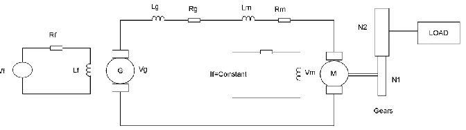
The Ward Leonard layout system is shown in Figure 1 below.
2
Figure 1Ward Leonard layout
The equations of the Ward–Leonard layout are as follows. The Kirchhoff’s law of voltages of the excitation field of the generator G is
1f f f f f
di
V R i L
dt
The voltage vg of the generator G is proportional to the current if , i.e.,
1
g f
V K i
The voltage vm of the motor M is proportional to the angular velocitym, i.e.,
2
m m
V K
The differential equation for the current ia is
1 2
2a
g m a g m g m f m
di
R R i L L V V K i K
dt
The torque Tm of the motor is proportional to the current ia, i.e.,
3
m a
T K i
The rotational motion of the rotor is described by
2 2 1 1 3 2 2 3 mm L m L m a
d
N N
J J B B K i
N dt N
Here, Jm is the moment of inertia and Bm the viscosity coefficient of the motor: likewise, for JL and BL of the load. From the above relations, we can determine the transfer function of the Ward– Leonard (WL) layout (including the load):
1 1 2 2 2 2 1 1 2 3 2 2 L WL ff f g m g m m L m L
N K K N G s V s N N
L s R L L s R R J J s B B K K
3
Where
1
2
y m
N N
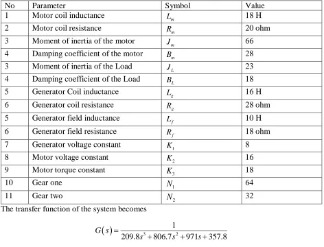
The parameters of the system is shown in Table 1 below.
Table 1 System parameter
No Parameter Symbol Value
1 Motor coil inductance Lm 18 H
2 Motor coil resistance Rm 20 ohm
3 Moment of inertia of the motor Jm 66
4 Damping coefficient of the motor Bm 28
3 Moment of inertia of the Load JL 23
4 Damping coefficient of the Load BL 18
5 Generator Coil inductance Lg 16 H
6 Generator coil resistance Rg 28 ohm
5 Generator field inductance Lf 10 H
6 Generator field resistance Rf 18 ohm
7 Generator voltage constant K1 8
8 Motor voltage constant K2 16
9 Motor torque constant K3 18
10 Gear one
1
N 64
11 Gear two
2
N 32
The transfer function of the system becomes
3 21
209.8 806.7 971 357.8
G s
s s s
And the state space representation becomes
9.9242 16.1380 5.9529 1
1 0 0 0
0 1 0 0
0 0 41.6667
x x u
y x
3. The Proposed Controllers Design2
4
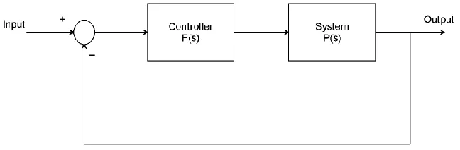
Hoptimal control synthesis solve the small-gain infinity-norm robust control problem; i.e., find a stabilizing controller F(s) for a system P(s) such that the closed-loop transfer function satisfies the infinity-norm inequality
1 1 sup max 1 1 1
y u y u
T T j
The block diagram of the system with Hoptimal control synthesis controller is shown in Figure 2 below
Figure 2 Block diagram of the system with Hoptimal control synthesis controller
An important use of the infinity-norm control theory is for direct shaping of closed-loop singular value Bode plots of control systems. In such cases, the system P(s) will typically be the plant augmented with suitable loop-shaping filters
The Hoptimal control synthesis controller transfer function is
4 33 2 20.269 1.034 1.245 0.4587
3.856 4.669 1.755 0.01709
s s s
s F
s s
s s
3.2HfOptimal Control Synthesis via -iteration Controller Design
Hoptimal control synthesis via -iteration compute the optimal Hcontroller using the loop-shifting two-Riccati formulae. The output is the optimal “” for which the cost function can achieve under a preset tolerance.
1 1
1 1
min ,;
1 ,;
y u y u
T ga d
T otherind
5
Figure 3 Block diagram of the system with Hoptimal control synthesis via -iteration controller
The Hoptimal control synthesis via -iteration controller transfer function is
4 3 3 220.2585 0.9939 1.196 0.4408
3.856 4.669 1.755 0.01709
G s s s s
s s s s
4. Result and Discussion
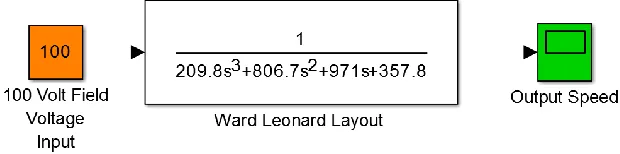
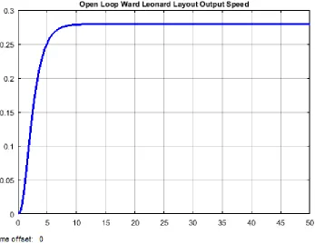
4.1Ward Leonard layout System Open Loop Response
The Simulink model of the open loop Ward Leonard layout system and the simulation result of the system for a constant field voltage input of 100 volt is shown in Figure 4 and Figure 5 respectively.
6
Figure 5 Simulation result
The simulation result shows that the Ward Leonard layout output speed is 0.75 rad/sec which needs a performance improvement.
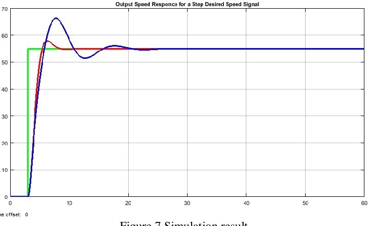
4.2Comparison of the Proposed Controllers for Tracking a Desired Step Speed
The Simulink model of the Ward Leonard layout system with Hoptimal control synthesis and
Hoptimal control synthesis via -iteration controllers are shown in Figure 6 below
Figure 6 Simulink model of the Ward Leonard layoutsystem with Hoptimal control synthesis and Hoptimal control synthesis via -iteration controllers
The simulation result of the Ward Leonard layoutsystem with Hoptimal control synthesis and
7
Figure 7 Simulation result
The performance data of the rise time, percentage overshoot, settling time and peak value is shown in Table 2.
Table 2 Step response data
No Performance Data Hoptimal Hoptimal via -iteration
1 Rise time 3.8 sec 3.8 sec
2 Per. overshoot 3.63 % 21.8 %
3 Settling time 8 sec 26 sec
4 Peak value 57 rad/sec 67 ad/sec
5. Conclusion
In this paper, a Ward Leonard layoutsystem is designed using a DC motor generator combination. In order to improve the performance of the system, a robust control technique with Hoptimal control synthesis and Hoptimal control synthesis via -iteration controllers are used. The open loop response of the system shows that the system needs improvement. The comparison of the proposed controllers is done to track a desired step speed and the results proves that the system with H optimal control synthesis controller improves the settling time and the percentage overshoot than the system with Hoptimal control synthesis via -iteration controller.
Reference
8
[2]. Mustefa J. et al. “DC Motor Speed Control with the Presence of Input Disturbance using Neural Network Based Model Reference and Predictive Controllers” International Research Journal of Modernization in Engineering Technology and Science, Vol. 2, Issue 4, 2020.
[3]. Panagiotis K. et al. “Fuzzy Q-Learning Agent for Online Tuning of PID Controller for DC Motor Speed Control” Algorithms for PID Controller (Special Issue), Vol. 11, Issue. 10, 2018.
[4]. N.L Ismail et al. “DC Motor Speed Control using Fuzzy Logic Controller” AIP Conference Proceedings, Vol. 1930, Issue. 1, 2018.
[5]. K. Priyanka et al. “DC Motor Control using PWM” International Journal of Innovative Science and Research Technology, Vol. 3, Issue. 2, 2018.
[6]. Ali A. Hassan et al. “Comparative Study for DC Motor Speed Control using PID Controller” International Journal of Engineering and Technology, Vol. 9, No. 6, pp 4181-4192, 2017.
[7]. Lubica M et al. “Speed Control of DC Motor” American Journal of Mechanical Engineering, Vol. 4, No. 7, pp 380-384, 2016.