Automatic Signal and Alarming System
To Avoid Engine Overheating
Md.Sourove akther Momin
1*, Mr. Md. Golam Kader
2, Pratik
Roy
3,Md.Sahid Hasan
4, Md. Mufrid Zuhane
5Department of Mechanical Engineering, Khulna University of Engineering & Technology,
Khulna-9203, BANGLADESH
E-mail:[email protected]
Abstract:
Modern technology is largely depends on automation and control system. Automation and control system refers the use of various control systems for operating equipment such as machinery, processes in factories, boilers and heat treating ovens, switching on telephone networks, steering and stabilization of ships, aircraft, automobile and other applications with minimal or reduced human intervention. The greatest advantage of automation and control system is that it saves labor. However, it is also used to save energy and materials and to improve quality, accuracy and precision. Because of these advantages, nowadays automation and control system is using in every sector. Automobile sector is not out of it. The aim of this project is to design and to develop such type of automatic control system for an engine which will aid in protecting the engine from over-heating by means of alarm and signal through a temperature sensor. This signal and alarming system mainly consists of temperature sensor circuit, micro-controller and LCD. The temperature sensor is fixed to the engine, and operating temperature is measured by this. This produces the alarm and signal when the engine temperature exceeds the set temperature limit. LCD continuously shows the operating temperature of engine.
Keywords: Automation; Control; Overheating;
Automobile
1
.Introduction
Generally, normally engines are designed to operate within a normal temperature range. For the proper emissions control, good fuel economy and performance a relatively constant operating temperature is very essential. But problems can arise when the engine run hotter than normal that resulting in engine overheating. Engine overheating is mainly caused by loss of coolant due to leaks in the cooling system. Other causes include a loose or broken fan belt, a defective water pump, clogged water jackets or radiator tubes, blocked radiator
thermostat or fan clutch[1]. Also, late ignition or valve timing, lack of engine oil, overloading the engine or high speed, high-altitude or hot-climate operation can cause engine overheating[4]. Freezing of the coolant could cause lack of the coolant circulation so that local hot spots and boiling develop. If a faulty TCS (Transmission-Controlled Spark) system prevents vacuum advance in any gear, or if the distributor vacuum advance is defective, overheating may result. Idling and slow-moving traffic can also cause the engine to overheat when combined with other problems[2]. If the engine is overheated for one of those problems, it may start to detonate. Then, engine may rattle and ping and lose power. If detonation occurs continuously, it may damage the rings, pistons and rod bearings. Overheating may cause piston scuffing. Engine overheating can cause an overhead cam to seize and break. Engine overheating may stress old radiator and heater hoses and cause them to burst under the additional pressure[5]. So, it is necessary to take some steps to avoid engine overheating. For these automatic signal and alarming system will be helpful. The system will alert driver by signal before overheating. It is known that overheating temperature is greater than 84⁰C for air-cooled engine and is greater than 70⁰C for water-cooled engine. So, this system works just before those temperatures (i.e.83⁰C & 69⁰C respectively).The design temperature of some engines is 90⁰C to 104⁰C; the temperature parameter can also be set in this system[6]. The automatic overheating signal and alarming system is designed to made awareness and to take proper action and repair.The working principle in this system is controlled by micro-controller. Temperature sensor provides input; LCD, buzzer and LED provide output. Micro-controllers are often used in automobile industries, because they are generally used to control a single process and execute simple instructions[3]. Micro-controllers do not require significant processing power.
2. Methodology
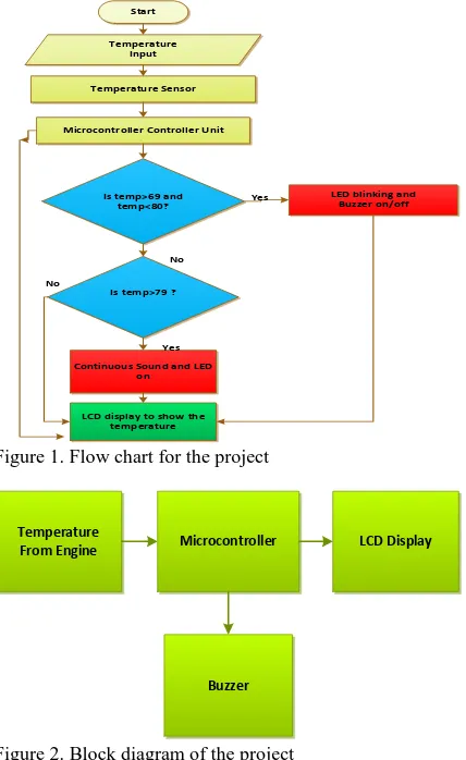
programmed with a microcontroller which will sound the buzzer alarm and control LED according to the temperature reading. Microcontroller is used to control the overall system automatically that reduces the design and control complexity. At first, temperature sensor is sensed temperature from the engine and sent it to the microcontroller. The microcontroller is programmed and temperature is shown in LCD. If the temperature is greater than 69 and less than 80 then LED start blinking and buzzer on/off, LCD display show the temperature. If the condition fails, then the temperature is again checked. If the temperature is greater than 79 then continuous sounds arises and LED switches on and is shown in LCD. Temperature will be shown in this system continuously.
Start Temperature
Input
Temperature Sensor
Microcontroller Controller Unit
Is temp>69 and temp<80?
Is temp>79 ?
Continuous Sound and LED on
LCD display to show the temperature
LED blinking and Buzzer on/off Yes
No
Yes No
Figure 1. Flow chart for the project
Temperature
From Engine Microcontroller LCD Display
Buzzer
Figure 2. Block diagram of the project
3. Components
The components of the system are as
follows:
At mega 8 Microcontroller
Temperature Sensor
LCD Display
Resistors
Buzzer
MOSFET
Power Supply
4.Circuit Diagrum
The circuit is connected to a 6 volt DC power supply. Pin 2,3,4,6,11,12,13 of micro-controller AT mega 8 is connected with LCD via variable resistor. In temperature sensor pin 1, 2 and 3 are GND, DQ and VCC respectively. Pin 14 of micro-controller is directly connected with pin 2 DQ of temperature sensor. In temperature sensor pin 3 VCC is connected to the pin 2 DQ via 4.7k resistor and pin 1 is ground. Pin 15 and 16 of micro-controller is connected to the buzzer and LED respectively. When temperature is greater than 69, buzzer and LED at flip-flop stage i.e. LED blinking and buzzer on-off (Figure 3). When temperature is greater than 79 buzzer and LED continuously on stage (Figure 4).Here any temperature can be set. Outside that condition the system is continuously show operating temperature of engine (Figure 5).
Figure 5. Circuit diagram when LED and Buzzer continuously on
5.Hardware Development and
Construction
At first the suitable programs are developed and then the programs are simulated by using Proteus software to check whether the programs were valid or not. Validation and correction of the simulation is really necessary. Then the programs are loaded into the ATmega8 microcontroller by using AVR software. Then the circuit board is made along with the microcontroller. The circuit is checked by using LED lights whether it works perfectly or not. After accomplishing the hardware it is associated with the temperature sensor. As it is a demo project and replicate the alternator by giving power to the system from a direct source. Now temperature sensor is connected to the engine from the circuit board. Then the system is given operating temperature of the engine and overheating alarm and signal when the engine temperature exceeds the set temperature limit.
6.Performane Test & Discussion
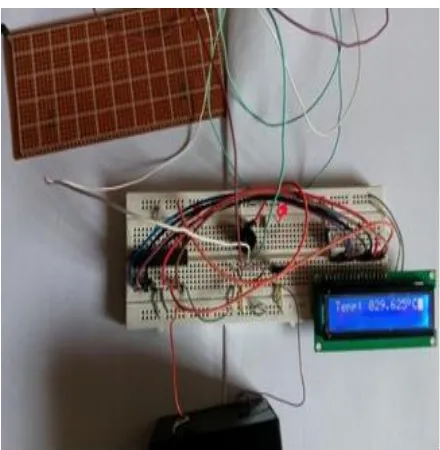
After design and construction the system was tested whether all the connection and whole circuit was working properly or not. The system was assembled with breadboard. To ensure the proper functioning of the components Digital millimeters (DMM) was used.
Figure 6. Testing system
Figure 7. Temperature Sensor Set in the Air-Cooled Diesel Engine
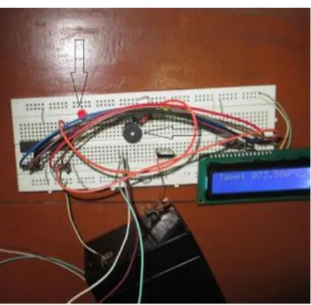
Figure 8. LED Blinking and buzzer on-off
Figure 9. Temperature Sensor Set in the Air-Cooled
Figure 10. Temperature Sensor Set in the Air-Cooled Petrol Engine
Figure 11. LED and buzzer continuously on and loudly
7. Conclusion
The automatic signal and alarming system to avoid engine overheating has been successfully designed and developed. Compared to other conventional methods, this system shows excellent performance with its reliable digital technology and it is cheaper and durable. The automatic overheat alarm and signal system is a promising system in terms of engine temperature response in the sensor, micro-controller and LCD. Thus the automatic signal and alarming system for overheating is a big boon as concerned with the automobile engine, aviation engine, generator, power plant, nuclear power plant and industrial applications. It increases engine-life and saves economical expenses. Based on the survey result, it is seen that the signal and alarming system has a rising demand and it is a good asset from the electronics perspective
8.References
[2] R. S. Khurmi, and J. K. Gupta, ”A Text Book Of Thermal Engineering(S.I. Unit)”, First Edition(Reprint-2003); S.Chand & Company Ltd. New Delhi.
[3] M. A. Laughton CEng., FIEE D. J. Warne CEng., FIEE, “Electrical Engineer's Reference Book”, Sixteenth edition, Reed Educational and Professional Publishing Ltd.
[4] Edward F. Obert, “ Internal Combustion Engines” , Third edition, international Textbook Company,Scranton, Pennsylvania.
[5] V.P. VASHANDANI,D.S.KUMAR, “ HEAT ENGINEERING”,Fourth edition,Metroplitan Book Co .Pvt. Ltd., New Delhi,India