S1 5 S1 4 S1 2 CH 1 VO L P8 34 12 R EV ( ) EA RT HD GN
RE V: SN : TB 2 R4 6 RV 1 C3 3 D1 3 D1 2 R5 9 R6 0 R5 78 R5 R5 5 R5 6 R5 3 R5 4 R5 1 R5 2 R4 9 R5 0 R4 7 R4 8 R6 2 U1 7 U1 3 C4 8 C4 1 C4 0 C3 9 C3 8 C3 6 C3 5 C3 4 TB 3 RV 8 R7 2 RV 9 RV 10 R6 9 R6 8 Q1 R7 3 Q2 RV 5 R6 4 3 R6 D1 1 RV 7 RV 6 RV 3 RV 4 RV 2 J5 J6 R6 5 U1 4 C4 3 C4 4 R7 1 U1 6 C5 0 C4 9 C4 7 U1 5 R6 6 R6 7 R7 0 C4 6 C4 5 U1 1 C4 2 C3 2 U1 2 D1 0 R4 1 R4 0 C3 0 C3 1 C2 9 C2 8 R4 3 R4 4 2 R4
U1 0 R6 1 C3 7 R3 9 R3 8 C9 E1 F1 K1 R4 5 D3 J3 TB 1 J2 C1 0 D2 D1
C8 C7 R9 R7 C5 R5 C4 C2 R2 R1 R3 2 K2 J1 D4 U8 C2 3 U7 C2 7 C2 4 C2 5 R3 4 R3 5 D9 L2 U9 C2 6 L1 C2 1 D8 R3 3 C2 2 J4 R3 6R 37 D5 D7 D6 R2 8 R2 3 R1 0 R1
9 3 R1
R2
1
R2
2 7 C1 7 R1 4 C1 4 R1 2 C1 U5 U6 C2 0 C1 9 R2
6 5 R2 0 R3 R3 1 9 R2
R2 4 C1 8 R1 6 U3 U4 C1 6R 20 8 R1 5 C1
R8 U1 C6 R6
U2 C1 1 R1
5 3 C1 12 1R R1 R3 R4 C3 C1
R2 7 + + + + + S8 1 2 3 4 ON 1 2 3 4 ON J1 MICROPHONE TB5 E1 SW5 SW4 TB3 TB2 TB1
SW1 SW2 SW3
K1 K2 K3 F1 F2 X1 X2 J2 P1 C16 D1 D2 U1 U2 U3 U4 U5 U6 U8 U9 U10 + -+ -+ -+ -+ -+ -T1 + -+ -+
-SAFEPATH P83167 REV B
AMBER GREEN TRB AUD TRB COM TRB NO TRB NC ALARM COM ALARM NO ALARM NC DV POWER DV STATUS CH PLAY LINE OUT LINE IN RM AUDIO RM TXD RM RXD RM POWER + + -TONE SEL 3 2 1 CND FLT ENB
RM ENABLE SYNC DV ENABLE LAMP TEST AUDIO STROBE SPK AMP 24V ALL CALL + -+ -GROUND FAULT ADJUST R53
SAFE
PATH
®
Installation, Testing, Operation,
and Maintenance Manual
FOR
Single Circuit
SAFE
PATH
®Systems
SCSP-4RP (108951)
SCSP-8RP (108952)
SCSP-15SP (108969)
273 Branchport Avenue, Long Branch, NJ 07740-6899 Ph: (732) 222-6880 Fax: (732) 222-2588 Toll Free 800-631-2148 Web Site: www.wheelockinc.com E-Mail: [email protected]
Typographical Notation Conventions
Thank you for using our products. Use this product according to this instruction manual. Please keep this instruction manual for future reference.
ANY MATERIAL EXTRAPOLATED FROM THIS DOCUMENT OR FROM WHEELOCK MANUALS OR OTHER DOCUMENTS DESCRIBING THE PRODUCT FOR USE IN PROMOTIONAL OR ADVERTISING CLAIMS, OR FOR ANY OTHER USE, INCLUDING DESCRIPTION OF THE PRODUCT'S APPLICATION, OPERATION, INSTALLATION AND TESTING IS USED AT THE SOLE RISK OF THE USER AND WHEELOCK WILL NOT HAVE ANY LIABILITY FOR SUCH USE.
Certain information contained in this manual has been extracted from the NFPA 72 Manual (1999 Edition) and the Life Safety Code 101™ Manual (2000 Edition).
Notation Conventions
This manual uses the following notation conventions:
WARNING: INDICATES A POTENTIALLY HAZARDOUS SITUATION THAT, IF NOT AVOIDED, COULD RESULT IN PROPERTY DAMAGE AND SERIOUS PERSONAL INJURY OR DEATH TO YOU AND OR OTHERS.
CAUTION: Indicates a potentially hazardous situation that, if not avoided, could result in minor or moderate injury. It may also be used to alert against unsafe practices.
P83636
Rev. G March 2003
TABLE OF CONTENTS
Typographical Notation Conventions……… iii
Table of Contents………. v
Table of Figures……… vii
Table of Tables………. ix
Chapter 1 – Safety Precautions………. 1-1
Section 1-1 – Read This Manual………. 1-1 Section 1-2 – Operational Safety……… 1-1 Section 1-3 – Compliance with Applicable Codes, Regulations, Laws, Standards,
And Guidelines………. 1-2
Section 1-4 – Property Insurance Recommendation……….. 1-2 Section 1-5 – Audio Output Considerations………. 1-3 Section 1-6 – RF Interference……… 1-3 Section 1-7 – General……….. 1-3
Chapter 2 – Overview and Features………. 2-1
Section 2-1 - Description………. 2-1 Section 2-2 – Enclosure and Configuration……….. 2-2 Section 2-3 – Nominal Electrical Data……….. 2-2 Section 2-4 – Module Configurations……… 2-3
Section 2-5 – Single Circuit SAFEPATH® Panel Basic Configuration…….…………. 2-3
Section 2-6 – Remote Microphone Station (RMS-2) (Optional)……… 2-3 Section 2-7 – Operation Modes………. 2-4 Section 2-8 – Glossary of Terms……….. 2-4
Chapter 3 – Installation and Setup……… 3-1
Section 3-1 – Introduction……… 3-1 Section 3-2 – Fire Alarm Control Panel Interface Wiring Applications………. 3-1 Section 3-3 – General Installation Instructions……… 3-2 Section 3-4 – Prepare a System Wiring Diagram……… 3-4 Section 3-5 – Mounting……… 3-13 Section 3-6 - System Checkout………. 3-15 Section 3-7 – Ground Fault Detection Sensitivity Adjustment……….. 3-18 Section 3-8 – Battery Care and Backup Battery Calculations………... 3-19
Chapter 4 – Operation……… 4-1
Section 4-1 – Introduction……….. 4-1 Section 4-2 – Operator’s Console………. 4-1 Section 4-3 – Supervision……….. 4-1 Section 4-4 – Actions That Initiate Alarms……….. 4-2
Chapter 5 – Operational Procedures……….. 5-1
Section 5-2 – To Make Live Announcements……….. 5-1 Section 5-3 – To Sound Evacuation Tone……… 5-1 Section 5-4 – To Reset Visual Appliances……… 5-2 Section 5-5 – To Acknowledge a Trouble Condition……….. 5-2
Chapter 6 – Periodic Testing and Maintenance………. 6-1 Section 6-1 – Periodic Testing……… 6-1 Section 6-2 – Qualified Personnel..……… 6-1 Section 6-3 – Miscellaneous Hardware Testing ………. 6-1
Chapter 7 – Troubleshooting………. 7-1 Section 7-1 – Troubleshooting……… 7-1
Section 7-2 - SAFEPATH® Module Replacement Procedure……….. 7-11
Section 7-3 – Single Circuit SAFEPATH®Module Wiring Diagram…………..…….. 7-12
Chapter 8 – Technical Data……….. 8-1 Section 8-1 – Mechanical……….. 8-1 Section 8-2 – Environmental………. 8-1 Section 8-3 – Electrical……….. 8-1
Chapter 9 – Module Descriptions……… 9-1 Section 9-1 – Introduction………. 9-1
Section 9-2 Single Circuit SAFEPATH® Motherboard (SCMB)………….…………. 9-3
Section 9-3 Digital Voice Module (MDX-2)………..……….…………. 9-6 Section 9-4 Power Supply/Battery Charger (DCPS)…….…..……….…… 9-8 Section 9-5 Supervised Audio System Amplifier/Signal Circuit Module, 40 Watts
(SAA-40S)……….………. 9-9
Section 9-6 Supervised Audio System Amplifier/Signal Circuit Module, 80 Watts
(SAA-80S/SE)………….……… 9-11
Section 9-7 Supervised Audio Line Level Module (SALL-15S)…………..…………. 9-13 Section 9-8 Notification Appliance Circuit Interface Module (NACIM)………….…… 9-15 Section 9-9 4-Zone Splitter Module (SC-SPL)………..………. 9-16 Section 9-10 Auxiliary Input Module (AIM-3)……….…………. 9-17 Section 9-11 Remote Microphone Station (RMS-2R)………..……. 9-19 Chapter 10 – MEA and Warranty………..……….. 10-1
List of Figures
Figure 2-1 Basic Capabilities of the Single Circuit SAFEPATH® Panel………... 2-2
Figure 2-2 Module Layout of a Typical Single Circuit SAFEPATH® Panel……… 2-5
Figure 3-1 Location of Plug-in Modules and Wire Connections……… 3-2 Figure 3-2 Strobe and Audio Output Connections………. 3-3 Figure 3-3 Wiring Diagram for Visual Notification Appliance Output……… 3-5 Figure 3-4 Wiring Diagram for Combination Audio/Visual Notification Appliances in
Central Amplifier Applications………. 3-6 Figure 3-5 Wiring Diagram for Combination Audio/Visual Notification Appliances in
Central Amplifier Applications………. 3-6 Figure 3-6 Wiring Diagram for Audio Notification Appliance Output……… 3-7 Figure 3-7 Wiring Diagram for Combination Audio/Visual Notification Appliances in
Central Amplifier Applications………. 3-7 Figure 3-8 Wiring Diagram for Audio Notification Appliances in Amplified Speaker
Applications……… 3-8
Figure 3-9 Wiring Diagram for Combination Audio/Visual Notification Appliances in
Amplified Speaker Applications……….. 3-8 Figure 3-10 Wiring Connection Locations……… 3-9 Figure 3-11 Dry Contact Input Connections………. 3-10 Figure 3-12 Alarm and Trouble Status Output Connections………. 3-10 Figure 3-13 Alarm Relay Contacts……… 3-11 Figure 3-14 Trouble Status Relay Contacts………. 3-11 Figure 3-15 Trouble Audible Connection………. 3-12 Figure 3-16 Input Power and Battery Connection Locations……… 3-13
Figure 3-17 Single Circuit SAFEPATH® Panel Mounting………. 3-14
Figure 3-18 Configuration DIP Switch Location on SCMB Module……….. 3-16
Figure 5-1 Single Circuit SAFEPATH® Panel Operator Console……… 5-3
Figure 7-1 Trouble LED Locations……… 7-2 Figure 7-2 Basic Troubleshooting Flowchart……….. 7-4 Figure 7-3 Digital Voice Module (MDX-2) Troubleshooting Flowchart……… 7-6
Figure 7-4 Single Circuit SAFEPATH® Module Wiring Diagram.……….. 7-13
Figure 9-1 Location of Plug-in Modules……… 9-2
Figure 9-2 Single Circuit SAFEPATH® Motherboard (SCMB)………. 9-5
Figure 9-3 Digital Voice Module (MDX-2)………..………. 9-7 Figure 9-4 Power Supply/Battery Charger (DCPS)………..……… 9-8 Figure 9-5 Supervised Audio System Amplifier/Signal Circuit Module, 40 Watts
Figure 9-6 Supervised Audio System Amplifier/Signal Circuit Module, 80 Watts
(SAA-80S/SE)……… 9-12
LIST OF TABLES
Table 3-1 SCMB DIP Switch Setting Description……… 3-17 Table 3-2 DIP Switch Settings for Available Tone Sounds……… 3-17
Table 3-3 Standby Current for Single Circuit SAFEPATH® Panel……….. 3-20
Table 3-4 Standby and Alarm Current for Single Circuit SAFEPATH® Modules………….. 3-21
Chapter 1 - Safety Precautions
Section 1-1 - Read This Manual
Personnel properly qualified in the application and use of life safety equipment ("qualified personnel") shall read this manual carefully before performing any actions to specify, apply, install, maintain and operationally test SAFEPATH® Panel products in accordance with the instructions in this manual.
This manual shall be kept with the SAFEPATH® Panel for reference during the life of the system. This
manual shall be made available to all qualified personnel who operate, test, maintain, or service
SAFEPATH® Panel products. It is strongly recommend that such personnel read and understand the
entire manual.
Section 1-2 - Operational Safety
WARNING: IF SAFETY PRECAUTIONS, INSTALLATION AND TESTING INSTRUCTIONS ARE NOT PERFORMED PROPERLY, THE SAFEPATH® PANEL MAY NOT OPERATE IN AN EMERGENCY SITUATION WHICH COULD RESULT IN PROPERTY DAMAGE AND SERIOUS INJURY OR DEATH TO YOU AND/OR OTHERS.
WARNING: IF THE TROUBLE CONDITION PROTECTIVE SIGNALING SYSTEM SOUNDS AND/OR FLASHES, IT IS A WARNING OF A POSSIBLE SERIOUS SITUATION AND REQUIRES IMMEDIATE ATTENTION.
CAUTION: The SAFEPATH® printed circuit boards are sensitive to static electricity and have delicate components mounted on a board. Discharge any static electricity from your body by touching a grounded object, such as a metal screw, which is connected to earth ground. Handle the board by its edges and be careful not to twist or flex it. The
SAFEPATH Panel is to be installed in a static free area, and the installer is to properly attach grounded wrist straps before touching any static sensitive areas. After handling
SAFEPATH® printed circuit boards, the panel should be tested in accordance with
Section 3-5 “System Checkout” of this manual to verify that the printed circuit board is functioning properly.
This SAFEPATH® Panel will not work without power. The SAFEPATH® Panel is powered by 120VAC or 220VAC. 24VDC re-chargeable batteries provide back-up power. If both sources of power are cut off for any reason, the SAFEPATH® Panel will not operate.
DO NOT assume any installation, operation and testing details not shown in this manual.
The SAFEPATH® Panel shall only be operated with the dead front panel properly in place.
WARNING: FOR PROPER OPERATION, THE SAFEPATH®PANELSHALL BE CONNECTED TO
A LISTED COMPATIBLE AND PROPERLY OPERATING CONTROL PANEL, WHICH CONTROLS ITS ACTIVATION. ALL EQUIPMENT SHALL BE PROPERLY INTERCONNECTED AND OPERATING. THE INSTALLER SHALL CHECK COMPATIBILITY OF ALL EQUIPMENT PRIOR TO INSTALLATION, OTHERWISE
THE SAFEPATH® PANEL AND/OR THE CONTROL PANEL MAY BE DAMAGED
Notification equipment cannot last forever. Even though SAFEPATH® Panel is expected to last up to ten years, any of its parts or components could fail before then. Therefore testing of the entire protective signaling system, including the SAFEPATH® Panel, all notification equipment, as well as all messages and their output channel, and priority assignment, shall be conducted at least twice each year, or more often as required by local, state and federal codes, regulations and laws, by qualified personnel. If the notification equipment is not working properly, immediately contact the installer and have all/any problems corrected immediately. Malfunctioning components should be replaced immediately. Do not attempt to repair malfunctioning components. Malfunctioning components should be returned for factory repair or replacement. In the event you cannot contact the installer, contact the manufacturer.
WARNING: CERTAIN HARDWARE FUNCTIONS ON THE SAFEPATH PANEL ARE NOT
SUPERVISED. IF ANY SUCH HARDWARE FUNCTIONS FAIL, THE SAFEPATH®
PANEL MAY NOT PROVIDE THE INTENDED WARNING AND/OR NOT INDICATE A TROUBLE CONDITION. THE FOLLOWING ARE NOT SUPERVISED:
1. THE "SHORT CIRCUIT" DETECTION CIRCUITRY FOR ANYONE OR ALL OF THE EIGHT CONTACT INPUTS.
THE FOLLOWING HARDWARE FAILURES WOULD PREVENT THE SAFEPATH
PANEL FROM INDICATING A TROUBLE CONDITION:
1. THE "OPEN CIRCUIT" DETECTION CIRCUITRY FOR ANY ONE OR ALL OF THE EIGHT CONTACT INPUTS.
2. THE AUDIO SUPERVISION CIRCUITRY FOR EACH OF THE TWO OUTPUT CHANNELS.
3.THE STATUS CONTACT.
THESE HARDWARE FUNCTIONS SHALL BE PERIODICALLY CHECKED FOR PROPER OPERATION.
Section 1-3 -
Compliance with Applicable Codes, Regulations, Laws,
Standards, and Guidelines
COMPLY WITH ALL OF THE LATEST APPLICABLE CODES, REGULATIONS, LAWS, STANDARDS, AND GUIDELINES.
WARNING: FOR EMERGENCY, HAZARDOUS, SECURITY, LIFE SAFETY, AND FIRE
PROTECTIVE SIGNALING SYSTEM APPLICATIONS USING THE SAFEPATH
PANEL INSTALLATION, TESTING AND MAINTENANCE SHALL BE PERFORMED
BY QUALIFIED PERSONNEL IN ACCORDANCE WITH ALL THE LATEST NATIONAL FIRE PROTECTION ASSOCIATION (NFPA), UNDERWRITER’S LABORATORY (UL), NATIONAL ELECTRIC CODE (NEC), OCCUPATIONAL SAFETY AND HEALTH ADMINISTRATION (OSHA), STATE, COUNTY, LOCAL, PROVINCE, DISTRICT, FEDERAL, AND OTHER APPLICABLE BUILDING AND FIRE STANDARDS, GUIDELINES, REGULATIONS, LAWS, AND CODES INCLUDING, BUT NOT LIMITED TO, ALL APPENDICES AND AMENDMENTS AND REQUIREMENTS OF THE LOCAL AUTHORITY HAVING JURISDICTION (AHJ). It is recommended that the local AHJ inspect and approve the proposed placement of all the notification appliances.
Section 1-4 - Property Insurance Recommendation
Section 1-5 - Audio Output Considerations
WARNING: AUDIBLE SIGNALS MAY MASK MEDICAL EQUIPMENT MONITORING ALARMS. WHERE MEDICAL EQUIPMENT MONITORING ALARMS ARE IN USE, DO NOT USE AUDIBLE SIGNALS; PROVIDE VISUAL NOTIFICATION APPLIANCES IN HIGHLY VISIBLE LOCATIONS.
CAUTION: The output of the audio system may not be heard in all cases. Sound can be blocked or reduced by walls, doors, carpeting, wall coverings, furniture, insulation, bed coverings, and other obstacles that may temporarily or permanently impede the output of the audio system. Sound is also reduced by distance and masked by background noise. The output of the audio system may not be sufficient to alert all occupants, especially those who are asleep, those who are hearing-impaired, those who are wearing devices that plug or cover the ears, and those who have recently used drugs or alcohol. The output of the audio system may not be heard by an alert person if the output device is placed in an area which is isolated by a closed door, or is located on a different floor from the person in a hazardous situation or is placed too far away to be heard over ambient noise such as, but not limited to, running water, traffic, air conditioners, machinery or musical appliances.
If live microphone announcements, audible tones and/or voice messages cannot be readily heard and understood clearly within the protected areas as intended, it will be necessary to increase the number and/or sound output intensity of speakers within those areas so that they are heard and understood clearly when activated.
Section 1-6 - RF Interference
The SAFEPATH® Panel has been tested and found to comply with the limits for a Class A digital device, pursuant to Part 15 of the FCC Rules. These limits are designed to provide reasonable protection against harmful interference when the equipment is operated in a commercial environment. This equipment generates, uses, and can radiate radio frequency energy and, if not installed and used in accordance with the instruction manual, may cause harmful interference to radio communications. Operation of this equipment in a residential area is likely to cause harmful interference in which case the user will be required to correct the interference at owners expense.
Section 1-7 - General
Each manufacturer's fire alarm control panel, and notification appliances operate differently and have different features. Before specifying, installing, operating, testing, maintaining or servicing a system, carefully read the installation, operation and testing manual for each piece of equipment and applicable codes.
Additional copies of this manual may be obtained from:
Wheelock, Inc.
273 Branchport Ave.
Chapter 2 - Overview and Features
Section 2-1- Description
General
The Single Circuit SAFEPATH® Panel is a stand alone, single channel, supervised audio fire and
emergency evacuation system. Figure 2-1 on Page 2-2 illustrates the basic capabilities of the Single Circuit SAFEPATH Panel.
The control panel that activates the Single Circuit SAFEPATH Panel can range from simple push
buttons to a sophisticated computer based control panel providing dry contact closures.
The SAFEPATH Panel does not sense an emergency condition or hazards such as fire; it is only a part
of a system that does sense such conditions. The SAFEPATHPanel, when activated, provides a pre-recorded tone and/or voice message(s) to notification appliances. When used as part of a protective signaling system, the SAFEPATH Panel must be properly connected to a compatible control panel that
has been approved by a nationally recognized testing laboratory ("LISTED") and to LISTED compatible notification appliances for proper operation.
THE SAFEPATH PANEL MUST BE PROPERLY INSTALLED, PROGRAMMED, AND CONNECTED
TO A COMPATIBLE FIRE ALARM CONTROL PANEL TO FUNCTION IN A VOICE EVACUATION SYSTEM.
WHEELOCK EXPRESSLY DISCLAIMS ALL LIABILITY FOR THE CONTENT, CLARITY AND LANGUAGES OF, AND OUTPUT CHANNEL AND PRIORITY LEVEL ASSIGNED TO, ANY AND ALL MESSAGES. IT IS ESSENTIAL THAT YOU HAVE MESSAGE CONTENT AND LANGUAGE, SEQUENCE, OUTPUT CHANNEL AND PRIORITY ASSIGNMENTS REVIEWED AND APPROVED BY QUALIFIED LEGAL AND SAFETY ADVISORS, QUALIFIED REPRESENTATIVE(S) OF OWNER(S) AND USER(S), AND AUTHORITIES HAVING JURISDICTION.
Standard Features
• One zone of audio and strobe NAC outputs.
• Multiple contact closure inputs
• A hand held, push-to-talk microphone (PTT) for live, emergency voice announcements and
instructions. The microphone overrides (mutes) any voice message or tones in progress.
• A multi-tone tone generator with 8 field selectable sounds for an optional evacuation signal.
• Visual NAC circuit of up to 2 amps at 24VDC. The visual NAC circuit may be selected to be
compatible with Wheelock, Inc. synchronized or non-synchronized visual notification appliances.
• Supervised Audio Amplifier module (SAA-40S, or 80S/SE) power 25, 70.7 or 100-volt speakers, or
Line Level Audio Amplifier (SALL-15S) to drive external power amplifiers and/or self-amplified speakers.
• Digital Voice Module (MDX-2) with a Standard Message Kit (SMK) containing 8 standard messages
• Full supervision with on-board diagnostics and trouble reporting circuits for:
• Audio NAC circuit wiring open and short conditions • Ground Fault detection
• Strobe NAC circuit wiring open and short conditions
• Self Amplified power output circuit wiring open and short conditions • Microphone open condition
• Optional remote microphone station • Digital Voice Module (MDX-2) • Alarm input activation wiring • Input voltage/low battery
• Built-in audible alert indicates any supervision loss
• Auxiliary trouble output for trouble signal connection
• Remote reporting via output contacts for system trouble or alarm activation.
• An internal 6-amp power supply/ 40Ah battery charger.
Optional Features
• Remote Microphone Station (RMS-2) for live, emergency announcements.
• Programmed Message Kit (PMK) for up to two minutes of messages tailored to customer’s needs. • Four Zone Audio Splitter (SC-SPL).
• Auxiliary Input Module (AIM-3) used to connect three Remote Microphone Stations or two Remote
Microphone Stations and a telephone page input.
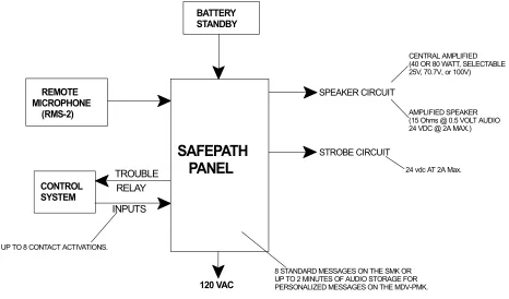
CONTROL SYSTEM
120 VAC REMOTE
MICROPHONE (RMS-2)
BATTERY STANDBY
SAFEPATH
PANEL
SPEAKER CIRCUIT
STROBE CIRCUIT
INPUTS TROUBLE
RELAY
8 STANDARD MESSAGES ON THE SMK OR UP TO 2 MINUTES OF AUDIO STORAGE FOR PERSONALIZED MESSAGES ON THE MDV-PMK. UP TO 8 CONTACT ACTIVATIONS.
AMPLIFIED SPEAKER (15 Ohms @ 0.5 VOLT AUDIO 24 VDC @ 2A MAX.)
24 vdc AT 2A Max. CENTRAL AMPLIFIED (40 OR 80 WATT, SELECTABLE 25V, 70.7V, or 100V)
Figure 2-1
Basic Capabilities of the Single Circuit SAFEPATH® Panel
Section 2-2 - Enclosure and Configuration
See Chapter 8 for Technical Specifications data.
Section 2-3 - Nominal Electrical Data
Section 2-4 - Module Configurations
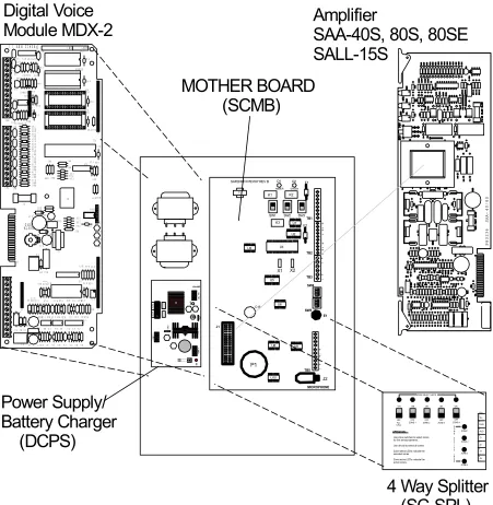
The Single Circuit SAFEPATH® Panel is equipped with a combination of the following modules:
There are ten modules in the Single Circuit SAFEPATH Panel product line.
The ten modules are:
SCMB (Single Circuit Motherboard)
DCPS (Power Supply/Battery Charger)
SAA-40S (40 Watt, Supervised Audio Amplifier Module with 2 Amps of strobe current)
SAA-80S/SE* (80 Watt, Supervised Audio Amplifier Module with 2 Amps of strobe current)
SALL-15S (Line Level, Supervised Audio Amplifier Module with 2 Amps of strobe current)
SC-SPL (Single Circuit Splitter - 4 Zone)
NACIM (Notification Appliance Circuit Interface Module)
MDX-2 (Digital Voice Module)
RMS-2 (Single Circuit Remote Microphone Station)
AIM-3 (Auxiliary Input Module)
* 100 Volt for Export Installations
Section 2-5 - Single Circuit
SAFE
PATH
®Panel Basic Configuration
Each Single Circuit SAFEPATH Panel is configured with:
SCMB (Single Circuit Motherboard)
MDX-2 (Digital Voice Module)
SMK (Standard Message Kit) or optional PMK (Programmed Message Kit)
One amplifier module
DCPS (Power Supply/Battery Charger)
Optional Modules:
One SC-SPL (Single Circuit Splitter-4 Zone)
Up to eight NACIM (Notification Appliance Circuit Interface Module)
Up to three RMS-2 (Remote Microphone Station)
One AIM-3 (Auxiliary Input Module)
The module layout of the Single Circuit SAFEPATH® Panel is shown in Figure 2-2 on Page 2-5.
Section 2-6 - Remote Microphone Station (RMS-2) (Optional)
Section 2-7 - Operation Modes
The SAFEPATH® Panel has two operation modes:
1. Standby 2. Alarm
Standby Mode
Standby is the normal mode. The SAFEPATH® Panel supervises the connections and internal
components to maintain proper operation. All strobes and speaker appliances are off.
Alarm Mode
Alarm mode occurs when an emergency signal is initiated manually, or by the FACP or control equipment.
Section 2-8 – Glossary of Terms
AHJ – Authority Having Jurisdiction
EOLR – End of Line Resistor
FACP – Fire Alarm Control Panel
NAC – Notification Appliance Circuit
NEC – National Electric Code (NFPA-70)
NFPA – National Fire Protection Association
PTT – Push to Talk (Microphone)
PCB - Printed Circuit Board
10
6
10 6
4 Way Splitter
(SC-SPL)
Amplifier
SAA-40S, 80S, 80SE
SALL-15S
Digital Voice
Module MDX-2
P 8 3 2 36 SA A -40/ 80 S1 5 S1 4 S1 2 CH 1 VO L P8 34 12 R EV ( ) EA RT HD GNRE V: SN : TB 2 R4 6 RV 1 C3 3 D1 3 D1 2 R5 9R6 0 R5 7R5 8 R5 5 R5 6 R5 3 R5 4 R5 1 R5 2 R4 9R5 0 R4 7R4 8 R6 2 U1 7 U1 3 C4 8 C4 1 C4 0 C3 9 C3 8 C3 6 C3 5 C3 4 TB 3 RV 8 R7 2 RV 9 RV 10 R6 9 R6 8 Q1 R7 3 Q2 RV 5 R6
43R6
D1 1 RV 7 RV 6 RV 3 RV 4 RV 2 J5 J6 R6 5 U1 4 C4 3 C4 4 R7 1 U1 6 C5 0 C4 9 C4 7 U1 5 R6 6 R6 7 R7 0 C4 6 C4 5 U1 1 C4 2 C3 2 U1 2 D1 0 R4 1 R4 0 C3 0 C3 1 C2 9 C2 8 R4 3 R4
4 2R4
U1 0 R6 1 C3 7 R3 9 R3 8 C9 E1 F1 K1 R4 5 D3 J3 TB 1 J2 C1
0 D2 D1
C8 C7R9 R7 C5 R5 C4 C2 R2 R1
R3 2 K2 J1 D4 U8 C2 3 U7 C2 7 C2 4 C2 5 R3 4R3 5 D9 L2 U9 C2 6 L1 C2 1 D8 R3 3 C2 2 J4 R3 6R 37 D5 D7 D6 R2 8 R2 3 R1 0 R1
9 3R1
R2
1
R2
2 7C1 7R14C1 4R12C1
U5 U6 C2 0 C1 9 R2
6 5R2 0R3
R3
1 9R2
R2 4 C1 8 R1 6 U3 U4 C1 6R
20 8R15C1
R8
U1 C6 R6
U2
C1
1
R1
5 3C1 121RR1
R3
R4 C3 C1
R2 7 + + + + + S8 1 2 3 4 ON 1 2 3 4 ON J1 MICROPHONE TB5 E1 SW5 SW4 TB3 TB2 TB1
SW1 SW2 SW3 K1 K2 K3 F1 F2 X1 X2 J2 P1 C16 D1 D2 U1 U2 U3 U4 U5 U6 U8 U9 U10 + -+ -+ -+ -+ -+ -T1 + -+ -+
-SAFEPATH P83167 REV B
AMBER GREEN DC BA T + -SW 1 AC AC AC + -DC SW 2 BA T FAIL NO NC C AC FAIL C NC NO SMP7P M
Power Supply/
Battery Charger
(DCPS)
ZONE SELECT LED'S
ON OFF ON ON OFF OFF ON OFF ON OFF ALL CALL
ZONE 1 ZONE 2 ZONE 3 ZONE 4
ZONE 1 ZONE 2 ZONE 3 ZONE 4 Z O N E A C T I V E L E D S Z4 Z3 Z2 Z1 AUD PWR ALL TB1 + _ + _ + _ + _ + _ + _ + _ OPERATION:
Use zone switches to select zones for live announcements. Use all-call to select all zones. Zone select LED's indicate the selected zones. Zone active LED's indicate the active zones.
MOTHER BOARD
(SCMB)
Figure 2-2.
Chapter 3 - Installation and Setup
Section 3-1 - Introduction
The lives of people depend upon the safe and proper installation of the SAFEPATH® Panel. Please read,
understand and carefully follow the specific installation instructions set forth below to avoid damage to the
SAFEPATH® Panel and equipment connected to it. Only qualified personnel in accordance with the
procedures in this manual should conduct installation.
WARNING: SHUT OFF ALL POWER BEFORE STARTING THE INSTALLATION. ELECTRICAL SHOCK CAN CAUSE DEATH OR SERIOUS INJURY.
WARNING: DO NOT CONNECT AC POWER OR BATTERY BACKUP POWER UNTIL SYSTEM WIRING HAS BEEN CONNECTED, MODULES HAVE BEEN INSTALLED, AND FIELD WIRING HAS BEEN INSPECTED.
CAUTION: The SAFEPATH® printed circuit boards are sensitive to static electricity and have delicate components mounted on them. Before handling either a board or any component on a board, discharge any static electricity from your body by touching a grounded object such as a metal screw, which is connected to earth, ground. Handle the board by its edges, and be careful not to twist or flex it. The
SAFEPATH® Panel is to be installed in a static free area and the user is to properly attach grounded wrist straps before touching any static sensitive areas. After handling SAFEPATH® printed circuit boards, verify that the printed circuit boards
are undamaged and functioning properly.
The installer, prior to installation should consult with the authorities having jurisdiction (AHJ).
Section 3-2 - Fire Alarm Control Panel Interface Wiring Applications
The SAFEPATH® Panel can be connected to either the FACP alarm output dry contact or to the
FACP Notification Appliance Circuit (NAC). If it is connected to the NAC, then the Notification Appliance Circuit Interface Module (NACIM) shall be used. Follow the NACIM instruction sheet (P83478) for proper mounting and wiring.
The SAFEPATH® Panel may be connected to either a “silenceable” or “non-silenceable” notification appliance circuit depending upon system requirements. When the SAFEPATH® Panel is connected to a “silenceable” NAC circuit on the FACP, activating the FACP’s alarm silence switch will silence it. The Strobe NAC circuit on the SAFEPATH® Panel will also be silenced. In order for the strobes to
remain in alarm when the audible is silenced, the Strobe NAC circuit must be connected to a “non-silenceable” NAC circuit on the FACP.
A SAFEPATH® Panel connected to a “non-silenceable” NAC circuit cannot be silenced from the
FACP.
“TROUBLE”, Form C relay terminals are available for monitoring the condition of the SAFEPATH®
IN8 IN7 IN6 IN5 IN4 IN3 IN2 IN1 Digital Voice Module MDX-2 S15 S14 S12 CH 1 VO L P8 34 12 R EV ( ) EA RT
HDGN
RE V: SN : TB2 R46 RV1 C33 D13 D12 R59 R60 R57 R58 R55 R56 R53 R54 R51 R52 R49 R50 R47 R48 R62 U1 7 U13 C48 C41 C40 C39 C38 C36 C35 C34 TB3 RV8 R72 RV9 RV1 0 R69 R68 Q1 R73 Q2 RV5 R64R63 D11 RV7 RV6 RV3 RV4 RV2 J5 J6 R65 U14 C43 C4 4 R71 U16 C50 C49 C47 U15 R66 R67 R70 C46 C45 U11 C42 C32 U12 D10 R41 R40 C30 C31 C29 C28 R43 R44 R42 U10 R61 C37 R39 R38 C9 E1 F1 K1 R45 D3 J3 TB1 J2
C10D2D1
C8 C7R9 R7 C5 R5 C4 C2 R2R1 R32 K2 J1 D4 U8 C23 U7 C27 C24 C25 R34R35 D9 L2 U9 C26 L1 C21 D8 R33 C22 J4 R36 R37 D5 D7 D6 R28 R23 R10 R19 R13 R2 1 R2
2 C17 R17C14 R14 C12
U5 U6
C2
0C1
9
R26 R25 R30
R31 R29 R24 C18 R16 U3 U4 C16R2 0 R18 C15
R8
U1 C6 R6
U2 C11 R15 C13 R12R11
R3
R4 C3 C1
R27 + + + + + S8 1 2 3 4 ON 1 2 3 4 ON J1 MICROPHONE TB5 E1 SW5 SW4 TB3 TB2 TB1
SW1 SW2 SW3
K1 K2 K3 F1 F2 X1 X2 J2 P1 C16 D1 D2 U1 U2 U3 U4 U5 U6 U8 U9 U10 + -+ -+ -+ -+ -+ -T1 + -+ -+
-SAFEPATH P83167 REV B
AMBER GREEN BA T + -TB
2 1RV
TB 3 RV 8 RV 5 D1 1 RV 7 RV 6 RV 3 RV 4 RV 2 TRB AUD TRB COM TRB NO TRB NC ALARM COM ALARM NO ALARM NC DV POWER DV STATUS CH PLAY LINE OUT LINE IN RM AUDIO RM TXD RM RXD RM POWER + + -TONE SEL 3 2 1 CND FLT ENB
RM ENABLE SYNC DV ENABLE LAMP TEST AUDIO STROBE SPK AMP 24V ALL CALL + -+ -TB1 TRB AUD TRB COM TRB NO TRB NC ALARM COM ALARM NO ALARM NC +
-TB3 +
-+ -RM AUDIO RM TXD RM RXD RM POWER 1 2 3 4 ON 1 2 3 4 ON SW5 SW4 TONE SEL
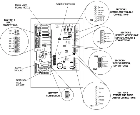
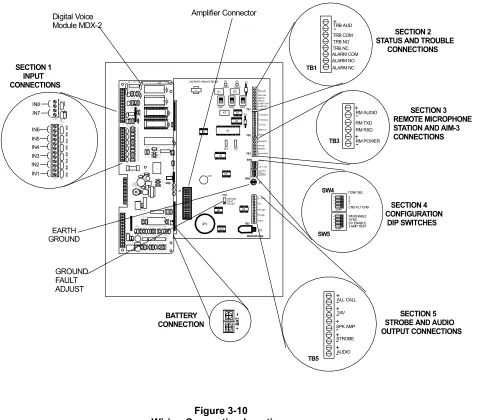
3 2 1 CND FLT ENB RM ENABLE SYNC DV ENABLE LAMP TEST TB5 + -+ -+ -AUDIO STROBE SPK AMP 24V ALL CALL + -+ -Amplifier Connector BATTERY CONNECTION SECTION 1 INPUT CONNECTIONS SECTION 2 STATUS AND TROUBLE CONNECTIONS
SECTION 3 REMOTE MICROPHONE STATION AND AIM-3 CONNECTIONS
SECTION 4 CONFIGURATION DIP SWITCHES
SECTION 5 STROBE AND AUDIO OUTPUT CONNECTIONS EARTH GROUND GROUND FAULT ADJUST R53 GROUND FAULT ADJUST Figure 3-1
Location of Plug-in Modules and Wire Connections
Section 3-3 - General Installation Instructions
Refer to Figure 3-1, which shows the location of modules and wiring connections used in the installation of the SAFEPATH® Panel.
Prepare a System Wiring Diagram
1. Using Section 3-4, prepare a complete system-wiring diagram. Keep a copy of the system-wiring diagram with the SAFEPATH® Panel manual as a permanent record of the system wiring.
Unpack and Check Inventory
2. Carefully unpack the SAFEPATH® Panel and make sure each item described on the packing slip
is present and undamaged.
Mounting
3. Mount the SAFEPATH® Panel and optional expansion modules in the desired locations as
described in Section 3-5.
5. Connect conduit fittings or bushings as needed through the knockouts provided on the top and bottom of the SAFEPATH® Panel.
Field Wiring Connections
6. Install field wiring in conduit when required, following the most current National Electrical Code (NFPA-70) and local codes for the type of system being installed. Make all necessary connections at any additional wiring or junction boxes.
7. Wire all ancillary equipment, power connections, and Fire Alarm Control Panel correctly and prepare all wires for hookup to the SAFEPATH®Panel.Do not connect Ancillary equipment or NAC speaker and strobe appliance wiring to the SAFEPATH Panel. This will be done starting with Step 13 of this procedure.
8. Connect supplied 10K Ohm, ¼ Watt test resistors to Strobe and Audio NAC Circuit output
connections on Motherboard. (If SALL-15S amplifier module is being used, connect a 10K Ohm ¼ Watt test resistor to the SPK AMP terminals also. See Figure 3-1 on Page 3-2 for location. Figure 3-2 is an enlarged picture of the referred area.
TB5
+
-+
-+
-AUDIO STROBE SPK AMP
24V ALL CALL
+
-+
SECTION 5 STROBE AND AUDIO OUTPUT CONNECTIONS
Figure 3-2
Strobe and Audio Output Connections
CAUTION: Provide proper strain relief for all wiring not in conduit.
1. Connect the SAFEPATH Panel to earth ground, following the National Electrical Code and local codes for the type of system being installed.
Wire gauge selection of the earth ground wiring should involve consideration of all factors, including maximum allowable wire resistance and length. The panel is tied to earth ground by connecting the ground terminals to an earth ground. The location of the ground terminals within the panel is shown in Figure 3-17 on Page 3-15.
CAUTION: Do not connect input voltage to any equipment until the field wiring has been tested, inspected and approved.
1. Check the integrity of all field wiring. Confirm that the specified cable is installed, and that there is continuity between required points (no open circuits), with no unwanted shorts to other conductors, chassis, or earth ground.
a. Verify that the field wiring complies with the instructions of this manual and the detailed wiring diagram prepared for this installation.
b. Ensure that no unwanted voltages are present on circuit conductors and ground.
c. Test all ungrounded connectors for electrical isolation from ground.
Measure and record the resistance of each NAC circuit. Conduct this test under reverse polarity conditions.
Initial Checkout
WARNING: TWO DIFFERENT SOURCES OF POWER MAY BE CONNECTED TO THE
SAFEPATH® PANEL. DISCONNECT BOTH SOURCES OF POWER BEFORE
SERVICING. FAILURE TO DO SO COULD RESULT IN PROPERTY DAMAGE, SERIOUS INJURY, OR DEATH TO YOU AND/OR OTHERS.
CAUTION: Connect the AC power source before connecting the battery backup power. Disconnect the battery backup power before disconnecting the AC power source.
1. Conduct the Initial Checkout procedures as described in Section 3-6 System Checkout.
Final Checkout
2. Remove all EOLRs on Audio and Visual NAC Circuits.
3. Connect all Strobe and Speaker NAC Circuits to the proper connections on the SAFEPATH®
Motherboard (SCMB). See Figure 3-2 on Page 3-3.
4. Connect all Optional Equipment to the SAFEPATH® Panel in accordance with each Installation
Sheet.
5. If the Strobe NAC Circuit is not being used connect a Wheelock, Inc. LISTED 10K Ohm, 1W EOLR to the terminals on the Mother Board.
6. If Ground Fault Detection is required, connect and align according to Section 3-7 Ground Fault Detection Sensitivity Adjustment.
7. Perform Final Checkout Procedures as described in Section 3-6 System Checkout. 8. Calculate and Install properly sized backup batteries. (Section 3-8)
Section 3-4 – Prepare a System Wiring Diagram
Wiring Guidelines
Although the SAFEPATH Panel products incorporate signal verification and noise filtering circuitry on
their inputs, induced voltages or noise on the input wiring can cause improper operation. Therefore, use shielded twisted pair wire for all dry contact input wiring.
The shield of each cable should be connected only at one end. Each shield of each cable that connects to the SAFEPATH Panel is to be connected to the grounding points provided near the knockout locations on the chassis (see Figure 3-17 on Page 3-15).
The National Electrical Code (NFPA-70) defines two types of circuits for protective signaling systems: power limited circuits and non-power limited circuits. The SAFEPATH® Panel circuits are non-power limited.
WARNING: ALL SAFEPATH® PANEL DRY CONTACT INPUT WIRING AND AUDIO WIRING
CAUTION: The National Electric Code limits the maximum number of conductors that can be installed in conduit and wiring boxes depending on the size of the conduit, the volume of the boxes, and the gauge of the wire used. Make sure that wiring used for
SAFEPATH® Panel installation complies with the latest NEC, NFPA, Local, State, County or Province requirements.
Field Wiring Connections
All SAFEPATH® Panel wiring terminals are designed to accept #12 AWG through #22 AWG wiring (one wire per terminal). Proper wire gage considerations for the NAC Circuit must take into account current requirements versus length of run.
Prepare System Wiring Diagram
.
1. Prepare a system-wiring diagram to include all Notification Appliances, ancillary equipment, and internal connections and power sources as required.
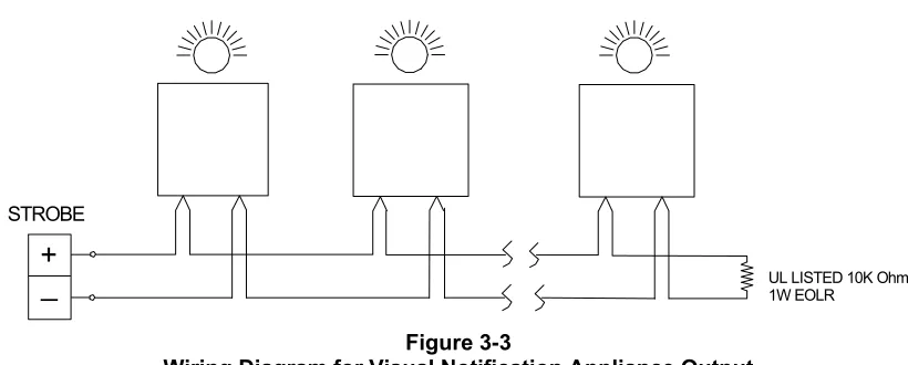
Visual Notification Appliance Output Wiring
Available alarm strobe current is a maximum of 2 Amps at 24VDC. Table 3-1 shows available strobe current using the standard calculation for a Temporal Code 3 signal. The SAFEPATH® Panel does not include any optional modules. Completecalculation information for other configurations is located in Section 3-8 Backup Battery Calculations.
Wire gauge may vary for each visual notification appliance output circuit on the panel. Wire gauge selection should involve consideration of all factors including, wire loop length, maximum current draw of each appliance, number of appliances, and maximum voltage drop allowable.
• Strobe NAC has a 24VDC, 2.0 amps maximum output
• Strobe NAC meets Class B supervision requirements for notification appliance circuits.
• Each output circuit shall have a UL LISTED, 10K Ohm, 1W, EOLR installed across the last visual notification appliance. If the output is unused, a UL LISTED, 10K Ohm, 1W, EOLR shall be placed across the output terminals. Each amplifier module contains the required number for the supervised outputs. If more are needed, recommend using Wheelock, Inc. End of Line Resistor Kit (Model Number EOLK, Part# 5076), which contains Eight (8) UL LISTED 10K Ohm 1W resistors.
Wiring Diagrams for Visual Portion of Audio/Visual Notification Appliances
+
_
STROBEUL LISTED 10K Ohm 1W EOLR
Figure 3-3
Wiring Diagram for Visual Notification Appliance Output
CAUTION: Do not loop wire under terminals. Break wire run to provide supervision of
+
_
+
_
AUDIO STROBE
UL LISTED 10K Ohm 1W EOLR UL LISTED 10K Ohm 1W EOLR
Figure 3-4
Wiring Diagram for Combination Audio/Visual Notification Appliances in Central Amplifier Applications
CAUTION: Do not loop wire under terminals. Break wire run to provide supervision of
connection.
+
_
+
_
AUDIO SPKR AMP
+
_
STROBE
UL LISTED 10K Ohm 1W EOLR
UL LISTED 10K Ohm 1W EOLR
UL LISTED 10K Ohm 1W EOLR
Figure 3-5
Wiring Diagram for Combination Audio/Visual Notification Appliances in Amplified Speaker Applications
CAUTION: Do not loop wire under terminals. Break wire run to provide supervision of
connection.
Central Amplified Speaker Notification Appliance Output Wiring
The audio alarm current of the amplifier module depends on the number of speakers on the circuit, length and gauge of wire of the audio circuit, and the audio mode in use.
When laying out each NAC circuit for the speakers, calculate the total wattage required. A good engineering practice is to not exceed 85% of the amplifier rating that you plan to use. If your calculations exceed this, an amplifier having increased power capacity is required or replacing the entire SAFEPATH®
Panel with greater capacity.
Wire gauge may vary for each audio appliance output on the panel. When:
• The central amplified output is either a selectable 25, 70.7 or a 100 volt audio output, rated for 40, or 80 watts maximum, depending upon the amplifier and its configuration. • The output meets Class B supervision requirements for notification appliance circuits.
• Each output circuit shall have a UL LISTED, 10K Ohm, 1W EOLR installed across the
last audio notification appliance. If the output is unused, it shall have a UL LISTED, 10K Ohm, 1W EOLR across the output terminals. Each amplifier module contains the required number for the supervised outputs. If more are needed, recommend using Wheelock, Inc. End of Line Resistor Kit (Model Number EOLK, Part# 5076), which contains Eight (8) UL LISTED 10K Ohm 1W resistors.
Wiring Diagrams for the Audio Portion of Audio/Visual Notification Appliances
+ _
AUDIO UL LISTED 10K Ohm1W EOLR
Figure 3-6
Wiring Diagram for Audio Notification Appliance Output
CAUTION: Do not loop wire under terminals. Break wire run to provide supervision of
connection.
+ _
+ _ AUDIO
STROBE UL LISTED 10K Ohm
1W EOLR
UL LISTED 10K Ohm 1W EOLR
Figure 3-7
Wiring Diagram for Combination Audio/Visual Notification Appliances in Central Amplifier Applications
CAUTION: Do not loop wire under terminals. Break wire run to provide supervision of connection.
Amplified Speaker Notification Appliance Power Output Wiring
Wire gauge selection for the amplified speaker notification appliance power output should involve consideration of all factors including wire loop length, maximum current draw of each appliance, number of appliances, and maximum voltage drop allowable.
• The Speaker Amp (SPK AMP) output is rated for 24VDC, 2.0 amps maximum.
• The output meets Class B supervision requirements for notification appliance circuits.
• The amplified speaker output is 15 Ohms, -5dBm maximum.
• Each output circuit shall have a UL LISTED, 10K Ohm, 1W EOLR installed across
Wiring Diagrams for Audio and SPK AMP Portions of Self-Amplified Audio/Visual Notification Appliances
+ _ + _
AUDIO SPKR AMP
UL LISTED 10K Ohm 1W EOLR
UL LISTED 10K Ohm 1W EOLR
Figure 3-8
Wiring Diagram for Audio Notification Appliances in Amplified Speaker Applications
CAUTION: Do not loop wire under terminals. Break wire run to provide supervision of connection
+
_
+
_
AUDIO SPKR AMP
+
_
STROBEUL LISTED 10K Ohm 1W EOLR
UL LISTED 10K Ohm 1W EOLR
UL LISTED 10K Ohm 1W EOLR
Figure 3-9
Wiring Diagram for Combination Audio/Visual Notification Appliances in Amplified Speaker Applications
Optional Equipment Connections
Remote Microphone Station (RMS-2)
See the Remote Microphone Station instruction sheet P83270 for additional information.
Notification Appliance Circuit Interface Module (NACIM)
See the Notification Appliance Circuit Interface Module instruction sheet P83487 for additional information.
4 Zone Splitter (SC-SPL)
See the Four Zone Splitter instruction sheet P83439 for additional information. Auxiliary Interface Module (AIM-3)
INTERNAL WIRING CONNECTIONS IN8 IN7 IN6 IN5 IN4 IN3 IN2 IN1 Digital Voice Module MDX-2 S15 S14 S12 CH 1 VO L P8 34 12 R EV ( ) EA RT
HDGN
RE V: SN : TB2 R46 RV1 C33 D13 D12 R59 R60 R57 R58 R55 R56 R53 R54 R51 R52 R49 R50 R47 R48 R62 U1 7 U13 C48 C41 C40 C39 C38 C36 C35 C34 TB3 RV8 R72 RV9 RV1 0 R69 R68 Q1 R73 Q2 RV5 R64R63 D11 RV7 RV6 RV3 RV4 RV2 J5 J6 R65 U14 C43 C4 4 R71 U16 C50 C49 C47 U15 R66 R67 R70 C46 C45 U11 C42 C32 U12 D10 R41 R40 C30 C31 C29 C28 R43 R44 R42 U10 R61 C37 R39 R38 C9 E1 F1 K1 R45 D3 J3 TB1 J2
C10D2D1
C8 C7R9 R7 C5 R5 C4 C2 R2R1 R32 K2 J1 D4 U8 C23 U7 C27 C24 C25 R34 R35 D9 L2 U9 C26 L1 C21 D8 R33 C22 J4 R36 R37 D5 D7 D6 R28 R23 R10 R19 R13 R2 1 R2
2 C17 R17C14 R14 C12
U5 U6
C2
0C1
9
R26 R25 R30
R31 R29 R24 C18 R16 U3 U4 C16R2 0 R18 C15
R8
U1 C6 R6
U2 C11 R15 C13 R12R11
R3
R4 C3 C1
R27 + + + + + S8 1 2 3 4 ON 1 2 3 4 ON J1 MICROPHONE TB5 E1 SW5 SW4 TB3 TB2 TB1
SW1 SW2 SW3
K1 K2 K3 F1 F2 X1 X2 J2 P1 C16 D1 D2 U1 U2 U3 U4 U5 U6 U8 U9 U10 + -+ -+ -+ -+ -+ -T1 + -+ -+
-SAFEPATH P83167 REV B
AMBER GREEN BA T + -TB
2 1RV
TB 3 RV 8 RV 5 D1 1 RV 7 RV 6 RV 3 RV 4 RV 2 TRB AUD TRB COM TRB NO TRB NC ALARM COM ALARM NO ALARM NC DV POWER DV STATUS CH PLAY LINE OUT LINE IN RM AUDIO RM TXD RM RXD RM POWER + + -TONE SEL 3 2 1 CND FLT ENB
RM ENABLE SYNC DV ENABLE LAMP TEST AUDIO STROBE SPK AMP 24V ALL CALL + -+ -TB1 TRB AUD TRB COM TRB NO TRB NC ALARM COM ALARM NO ALARM NC +
-TB3 +
-+ -RM AUDIO RM TXD RM RXD RM POWER 1 2 3 4 ON 1 2 3 4 ON SW5 SW4 TONE SEL
3 2 1 CND FLT ENB RM ENABLE SYNC DV ENABLE LAMP TEST TB5 + -+ -+ -AUDIO STROBE SPK AMP 24V ALL CALL + -+ -Amplifier Connector BATTERY CONNECTION SECTION 1 INPUT CONNECTIONS SECTION 2 STATUS AND TROUBLE CONNECTIONS
SECTION 3 REMOTE MICROPHONE STATION AND AIM-3 CONNECTIONS
SECTION 4 CONFIGURATION DIP SWITCHES
SECTION 5 STROBE AND AUDIO OUTPUT CONNECTIONS EARTH GROUND GROUND FAULT ADJUST R53 GROUND FAULT ADJUST Figure 3-10
Wiring Connection Locations
Dry Contact Input Wiring
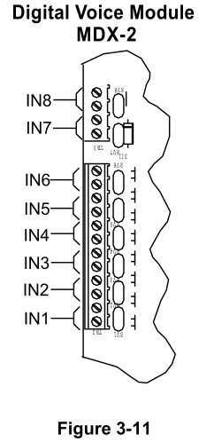
The dry contact inputs shall be dry contacts or open collector of a transistor. The locations of the dry contact inputs are shown in Figure 3-10 Section 1. A magnified view of this area on the Motherboard (SCMB) is shown in Figure 3-11 on Page 3-11.
• The dry contact input meets the requirements for non-power limited fire protective signaling
circuits as defined in the National Electrical Code. The dry contact inputs are unsupervised. • The field wiring for the dry contact input shall not exceed 100 Ohms of resistance or 0.050 µF of
capacitance.
IN8 IN7
IN6 IN5 IN4 IN3 IN2
IN1 TB2 1 RV
TB3 RV 8
RV 5
D1 1 RV 7
RV 6
RV 3
RV 4
RV 2
Digital Voice Module MDX-2
Figure 3-11
Dry Contact Input Connections
ALARM STATUS OUTPUT CONTACT WIRING
TB1
TRB AUD
TRB COM TRB NO TRB NC ALARM COM ALARM NO ALARM NC
+
-Motherboard (SCMB)
Figure 3-12
Alarm and Trouble Status Output Connections
The location of the Alarm Status output connections are shown in Figure 10 Section 2 on Page 3-10. A magnified view of this area on the Mother Board is shown in Figure 3-12 on Page 3-11.
• Wire gauge selection of the Alarm Status output contact wiring should involve consideration of all factors including, wire loop length, maximum current capacity, and maximum voltage drop allowable.
• The Alarm Status output contact is Form C, rated for 0.5 amps at 24VDC, resistive load. • For terminal connection details of the Alarm Status output contact (shown and marked in
ALARM COM
ALARM NO
ALARM NC
6
7
8
TB1
Figure 3-13 Alarm Relay Contacts
System Trouble Status Output Contact Wiring
The location of the Trouble Status output connections are shown in Figure 10 Section 2 on Page 3-10. A magnified view of this area on the Mother Board is shown in Figure 3-12 on Page 3-11.
• Wire gauge selection of the system Trouble Status output contact wiring should involve
consideration of all factors including, wire length, maximum current capacity, and maximum voltage drop allowable.
• The system Trouble Status output contact is Form C, rated for 0.5 amps at 24 VDC,
resistive load.
• For a detail of the system Trouble Status output contact Terminal connections (shown and marked in the trouble condition), see Figure 3-14.
TRB COM
TRB NO
TRB NC
3
4
5
TB1
Figure 3-14
Trouble Status Relay Contacts
Trouble Audible Output Wiring
• Wire gauge selection of the System Trouble Output Contact wiring involves consideration of all factors including wire loop length, maximum current capacity, and maximum voltage drop allowable.
• The Trouble Audible output is rated for 24VDC, 0.1 amps maximum. The output is
unsupervised.
1 2
TB1
TRBL AUDIO 24VDC
GRND
+ _
Figure 3-15
Trouble Audible Connection
Ground Fault Detection Wiring
On the Mother Board, connect Earth Ground Connection (E1) as shown on Figure 3-1 on Page 3-2 to the Chassis Ground (Figure 3-17 on Page 3-15). Make sure that chassis ground is at earth ground or to the common ground of the FACP. Conduct the sensitivity adjustment as described in Section 3-7 Ground Fault Detection Sensitivity Adjustment.
POWER CONNECTION REQUIREMENTS
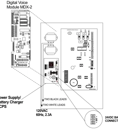
The Single Circuit SAFEPATH® Panel contains a 24VDC, 6 Amp Power Supply and a 40AH Battery
Charger for the battery backup. Connections for the input power and batteries are shown in Figure 3-16 on Page 3-14. Calculate proper backup battery requirements using Section 3-8.
WARNING: IT IS IMPORTANT THAT THE WIRING USED FOR INPUT VOLTAGE WIRING IS LARGE ENOUGH TO CARRY THE MAXIMUM CURRENT REQUIRED BY THE
SAFEPATH PANEL WITHOUT EXCESSIVE VOLTAGE DROP. IF VOLTAGE
DROPS FROM AC POWER LINE LOADING AND WIRING RESISTANCE IS NOT
WITHIN THE SPECIFIED OPERATING VOLTAGE RANGE, THE SAFEPATH®
10 6 10 6
Digital Voice
Module MDX-2
S1 5 S1 4 S1 2 CH1 VO L P8 34 12 R EV ( ) EA RT HDGNRE V: SN : TB2 R46 RV1 C33 D13 D12 R59 R60 R57R58 R55 R56 R53 R54 R51 R52 R49 R50 R47 R48 R62 U1 7 U13 C48 C41 C40 C39 C38 C36 C35 C34 TB3 RV8 R72 RV9 RV10 R69 R68 Q1 R73 Q2 RV5 R64 R63 D11 RV7 RV6 RV3 RV4 RV2 J5 J6 R65 U14 C43 C4 4 R71 U16 C50 C49 C47 U15 R66 R67 R70 C46 C45 U11 C42 C32 U12 D10 R41 R40 C30 C31 C29 C28 R43 R44 R42 U10 R61 C37 R39 R38 C9 E1 F1 K1 R45 D3 J3 TB1 J2
C10 D2D1
C8 C7R9 R7 C5 R5 C4 C2 R2 R1
R32 K2 J1 D4 U8 C23 U7 C27 C24 C25 R34 R35 D9 L2 U9 C26 L1 C21 D8 R33 C22 J4 R36R37 D5 D7 D6 R28 R23 R10 R19 R13 R21 R22 R14 R17
C17 C14 C12
U5 U6 C2 0 C1 9
R26 R25 R30
R31 R29 R24 C18 R16 U3 U4 C16R20 R18 C15
R8
U1 C6 R6
U2 C11 R15 C13 R12R11
R3
R4 C3 C1
R27 + + + + + S8 1 2 3 4 ON 1 2 3 4 ON J1 MICROPHONE TB5 E1 SW5 SW4 TB3 TB2 TB1
SW1 SW2 SW3
K1 K2 K3 F1 F2 X1 X2 J2 P1 C16 D1 D2 U1 U2 U3 U4 U5 U6 U8 U9 U10 + -+ -+ -+ -+ -+ -T1 + -+ -+
-SAFEPATH P83167 REV B
AMBER GREEN DC BA T + -SW 1 AC AC AC + -DC SW 2 BA T FAIL NO N C C AC F AIL C N C NO SMP7 PM
Power Supply/
Battery Charger
DCPS
BA T +-TWO BLACK LEADS
TWO WHITE LEADS
120VAC
60Hz, 2.3A
24VDC BATTERY CONNECTION
Figure 3-16
Input Power and Battery Connection Locations
Section 3-5 - Mounting
Location
The SAFEPATH® Panel shall be mounted in a location within the environmental limits specified in the
latest UL Standard 864 for indoor control panels. The SAFEPATH® Panel shall not be located in a
hazardous area.
Procedure
1. See Figure 3-17 on Page 3-15 for SAFEPATH® Panel mounting hole layout. 2. Remove Amplifier Module from the enclosure.
3. Mark and drill mounting holes for appropriate screws and anchors to ensure secure mounting to the type of surface at the selected location.
4. Prevent dust and dirt contamination of the SAFEPATH® Panel during installation. This
contamination can interfere with the operation and reduce the expected life of the equipment.
5. Open the door and mount the SAFEPATH Panel at the selected location. Use care to avoid damage to the module PC boards during installation. Do not apply excessive pressure to any PC board or its components, including field wiring terminals and connectors.
6. Replace Amplifier Module. Plug in Microphone.
7. For SAA-40S, 80S Amplifier Modules, set 25V/70V Switch to the correct setting for speakers. See Figure 9-5 on Page 9-10 (SAA-40S) or Figure 9-6 on Page 9-12 (SAA-80S/SE).
17.00" 14.00"
Conduit Entrances (Top and Bottom)
Ground Terminals
Figure 3-17
Section 3-6 System Checkout
Refer to NFPA 72 (1999 Edition) for guidelines on testing notification systems.
CAUTION: If a malfunction, or system trouble occurs during testing, STOPTESTING. Correct the problem before you resume testing.
Insure that speaker and strobe NAC Circuits are not connected to the SAFEPATH®Panel, and that 10K Ohm ¼W EOLR test resistors are connected in their place on the Mother Board.
1. Place switches on the Single Circuit Motherboard (SCMB) (Figure 3-10, Section 4 on Page 3-10 or Figure 3-18 on Page 3-17 for enlarged view) as follows:
DIP Switch SW4: TONE SEL, 3 – OFF, 2 – ON, 1 – ON, GND FLT ENB – OFF
DIP Switch SW5: RM ENABLE – OFF, SYNC – ON, DV ENABLE – ON, LAMP TEST - OFF
AUTOMATIC /MANUAL Switch: UP or “AUTOMATIC” position.
CAUTION: Connect the AC power source before connecting the battery backup power. Disconnect the battery backup power before disconnecting the AC power source. 2. Connect AC Power, then connect battery backup.
The green System Normal LED indicator on the Motherboard should be “ON” to indicate normal operation. If the amber system trouble LED is “ON”, a trouble condition is indicated. Refer to Chapter 7 "Troubleshooting and Servicing" to diagnose and correct the trouble condition.
Initial Checkout
3. With both AC Power and battery backup power applied observe the following indicators:
Single Circuit Motherboard (SCMB) (See Figure 9-2 ) TROUBLE / NORMAL LEDs Yellow “OFF”, Green “ON” Digital Voice Module (MDX-2) (See Figure 9-3)
LED D5 (Green) “ON” LED D6 (Yellow) “OFF” LED D7 (Yellow) “OFF”
Amplifiers (SAA-40S, SAA-80S/SE, SALL-15S)
SAA-40S, SAA-80S/SE (See Figure 9-5 for SAA-40S or Figure 9-6 for SAA-80S/SE) LED D15 (STR) “OFF”
LED D10 (SPK) “OFF” LED D6 (AMP) “OFF”. SALL-15S (See Figure 9-7) LED D16 (STROBE) “OFF” LED D13 (AUDIO) “OFF” LED D10 (PWR) “OFF” LED D3 (AMP) “OFF”.
4. Play first message by momentarily shorting IN1 on the Digital Voice Module (MDX-2). Relay on SCMB clicks at 1 click per second. When message ends, relay will stop clicking. Amplifier Modules: All LEDs “OFF”.
5. Key Microphone in panel. Relay on SCMB clicks at 1 click per second. When microphone push to talk (PTT) is released, clicking will continue until the RESET Switch is depressed (See Figure 5-1 on Page 5-3 for location). Amplifier Modules: All LEDs “OFF”.
6. Disconnect Battery Backup, then disconnect AC Power.
Final Checkout
CAUTION: If a malfunction, or system trouble occurs during testing, STOPTESTING. Correct the problem before you resume testing.
CAUTION: Connect the AC power source before connecting the battery backup power. Disconnect the battery backup power before disconnecting the AC power source.
1. Set Configuration Switches to desired settings for supervision tone. See Figure 3-18 on Page 3-17 for switch location on the Motherboard (SCMB). See Tables 3-2 and 3-3 for switch descriptions.
NOTE: The tone selected is used to supervise the amplifiers in STANDBY condition. It is also the tone when the AUTOMATIC/MANUAL switch is placed in the MANUAL position. The tone will also play in ALARM if DIP Switch SW5, DV ENABLE is OFF and the input contact closure is placed on the CH PLAY terminals on the Motherboard.
1
2
3
4
O N
1
2
3
4
O N
SW5
SW4
TONE SEL3 2 1
CND FLT ENB
RM ENABLE SYNC DV ENABLE LAMP TEST
Motherboard
SCMB
Figure 3-18
Table 3-1
SCMB DIP Switch Setting Description
DCDC DIP Switch SETTING/DESCRIPTION
SW4 Position 1 (GND FLT ENB)
GROUND FAULT ENABLE enables the ground fault detection circuit on the Motherboard
SW4 Position 2, 3, 4 (1, 2, 3)
MULTITONE SELECT selects 1 of 8 tones used for the secondary evacuation signal. Use chart below to select the tone.
SW4Position 1, (LAMP
TEST) LAMP TEST when enabled lights all the LED indicators on the Motherboard, and the Amplifier Module.
SW5 Position 2, (DV
ENABLE) DIGITAL VOICE ENABLE when enabled, allows the MDX-2 to transmit messages through the SAFEPATH® Panel.
SW5 Position 3,
(SYNC) SYNCHRONIZED STROBES ENABLE. “ON” enables Strobe NAC to work with Wheelock’s synchronized strobes.
SW5 Position 4, (RM ENABLE)
REMOTE MICROPHONE ENABLE. “ON” enables optional
Remote Microphone Station. “OFF” disables Remote Microphone Station circuit.
Table 3-2
DIP Switch Settings for Available Tone Sounds
TONE SOUND SW4-2 1 SW4-3 2 SW4-4 3
Horn (Continuous) ON ON ON
Bell (1560 Hz Modulated) ON OFF ON
March Time Horn (.25 Sec ON, .25 Sec OFF) OFF OFF ON
Code-3 Horn (ANSI S3.41 Temporal) ON ON OFF
Code-3 Tone 500Hz (ANSI S3.41 Temporal) OFF ON ON
Slow Whoop (500-1200Hz Sweep) OFF ON OFF
Siren (600-1200 Hz Sweep) ON OFF OFF
HI/LO (1000/800 Hz) OFF OFF OFF
2. Connect AC Power, and then connect battery backup.
3. With both AC Power and battery backup power applied observe the following indicators:
Single Circuit Motherboard (SCMB) (See Figure 9-2)
TROUBLE / NORMAL LEDs Yellow “OFF”, Green “ON”
Digital Voice Module (MDX-2) (See Figure 9-3) LED D1 (Green) “ON”
LED D2 (Yellow) “OFF” LED D3 (Yellow) “OFF”
Amplifiers (SAA-40S, SAA-80S/SE, SALL-15S)
SAA-40S, SAA-80S/SE (See Figure 9-5 for SAA-40S or Figure 9-6 for SAA-80S/SE)
LED D15 (STR) “OFF”
LED D10 (SPK) “OFF”
LED D6 (AMP) “OFF”
SALL-15S (See Figure 9-7)
LED D13 (AUDIO) “OFF”
LED D10 (PWR) “OFF”
LED D3 (AMP) “OFF”
4. Play each messages by momentarily shorting IN1 through IN8 in turn on Digital Voice Module. See Figure 3-11 on Page 3-11.
Relay on SCMB clicks at 1 click per second during the playing of each message.
Message will broadcast on all appliance circuits. If Strobe NAC circuits are in use, Strobes will also flash.
5. Key Microphone in panel. Relay closure can be heard.
Message will broadcast on all appliance circuits. If Strobe NAC circuits are in use, Strobes will also flash.
6. If Remote Microphone Station (RMS-2) or the AIM-3 is included, enable it by switching SW5-4 (RM ENABLE) to “ON” on the Single Circuit Motherboard (SCMB).
7. Test the Remote Microphone Station.
8. System is fully operational.
Additional system checkout should include: Testing all Alarm and Trouble circuits.
Testing all connections to equipment that is interconnected with the SAFEPATH® Panel.
WARNING: ALL PROTECTIVE SIGNALING SYSTEMS REQUIRE PERIODIC TESTING. ALL PROTECTIVE SIGNALING SYSTEM EQUIPMENT SHALL BE TESTED BY QUALIFIED PERSONNEL AT LEAST TWICE A YEAR FOR PROPER OPERATION, OR MORE OFTEN IF REQUIRED BY CODES, REGULATIONS AND LAWS. FAILURE TO MAINTAIN AND TEST PROTECTIVE SIGNALING SYSTEM EQUIPMENT CAN RESULT IN NOT DETECTING EQUIPMENT FAILURE THAT CAN CAUSE PROPERTY DAMAGE AND SERIOUS PERSONAL INJURY OR DEATH TO YOU AND/OR OTHERS DURING AN EMERGENCY SITUATION.
Section 3-7 – Ground Fault Detection Sensitivity Adjustment
Ground fault detection sensitivity can be adjusted for a set point between 40K Ohms and 500K Ohms. Selecting a high resistance set point will increase the circuit sensitivity to ground fault conditions. A high resistance may cause many false trouble conditions.
Selecting a low resistance will decrease the circuit sensitivity and will greatly reduce susceptibility to false trouble conditions. The lower resistance allows for lower ground fault resistance before a ground fault conditions occurs.
Before the sensitivity is adjusted, it is imperative to correct (clear) all trouble conditions.
NOTE: The ground fault detection sensitivity set-point shall be the same value as the FACP.
Adjustment Procedure
1. Place "GRND FLT ENB DIP switch in the ON position (SW4, POS 1). See Figure 3-18 on Page 3-17.
3. Rotate the shaft of the Ground Fault Detection Sensitivity potentiometer (R53) fully counterclockwise. (See Figure 9-2 on Page 9-5 for location) The potentiometer is a 12-turn device, there will be need to rotate the shaft repeatedly. The potentiometer produces a clicking sound when rotated beyond its end point.
4.
On the Mother Board (SCMB), place a resistor with the desired set-point value (40K Ohm to 500K Ohm, +/- 5% Tolerance) between the +24VDC terminal on TB4 and the earth ground terminal. See Figure 3-10 on Page 3-10.5. Slowly rotate the shaft of the Ground Fault Detection Sensitivity potentiometer clockwise. When a ground fault is indicated by the trouble LED's, the sensitivity set-point is set correctly.
6. Disconnect the resistor used to set the sensitivity level.
7. Reconnect the wire between the earth ground terminal on the Mother Board and earth ground.
Section 3-8 - Battery Care and Backup Battery Calculations
Installation and Care of Sealed Lead Acid Batteries
Sealed lead acid batteries are designed to operate in standby service for approximately five years. This is based upon a normal service condition where there is an ambient temperature of 20 degrees C (68 degrees F) and batteries are completely discharged once every three months. LENGTH OF SERVICE LIFE WILL BE DIRECTLY AFFECTED BY THE NUMBER OF DISCHARGE CYCLES, DEPTH OF DISCHARGE, AND AMBIENT TEMPERATURE.
Use Guidelines:
Avoid installation and/or operation in close proximity to heat sources. While the operating temperature range is 0 to 49 degrees C (32-120 degrees F), battery life will be maximized at an ambient temperature of 20 degrees C (68 degrees F).
Batteries may generate ignitable gases. Because of this, batteries shall be installed in a well-ventilated location, away from spark producing equipment.
Batteries shall not be installed in an atmosphere where organic solvents or adhesives may be present. The batteries shall not be cleaned with oils, thinners, or similar substances. The case and cover of the batteries are ABS plastic resin, which may suffer damage from these chemicals.
Batteries shall not be installed in a heavy vibration or shock location.
Batteries shall have a minimum separation of ¼” between cells.
Insulated gloves shall always be worn when handling batteries.
WARNING: Batteries shall not be crushed, incinerated, or dismantled. The electrolyte contains sulfuric acid, which can cause serious damage to eyes and skin. If contact does occur, flush with water and seek immediate medical attention.
Batteries of different capacities, age, or manufacturer shall not be used together.
Battery Storage
Batteries which are to be stored for an extended period of time should be given a supplement charge monthly. Batteries should never be stored in a discharged condition.