Copyright to IJIRSET www.ijirset.com 2035
DESIGN AND ANALYSIS OF PRESSURE
VESSEL AMALGAMATING WITH
SELECTION OF MATERIAL USED IN
MARINE APPLICATION
Prof. Nitinchandra R. Patel
1, Avinash Vasava
2, Jalesh Vasava
3, Alpesh
Kunapara4, Savan Patel
5 Assistant Professor, Department of Mechanical Engineering, G.H. Patel college of Engineering & technology,Vallabh vidyanagar, Gujarat, India1
Final year student, Department of Mechanical Engineering, G.H. Patel college of Engineering & technology,
Vallabh vidyanagar, Gujarat, India2,3,4,5
Abstract: The current phase of times is experiencing problems in pressure vessel design in marine substation. Here a small move towards designing a pressure vessel for marine substation is focused by analysis of pressure vessels for different pressure vessels materials. This research paper consists of analysis of pressure vessels by considering stresses induced in the materials of different standards. We have analysed different type of materials with the help of depth to be placed from sea surface. For particular selected condition, analytical calculation is done to find out the thickness of shell and different end closures. Accordingly we are going to evaluate better material for a marine substation by different consideration. This paper will be helpful in better designing of marine substation’s pressure vessels as good as possible. Further we have compared the result obtained from analytical calculation and by using MATLAB programming.
Keywords: Pressure vessel design, MATLAB, Optimum thickness, Best material evaluation.
I. INTRODUCTION
A concept for generation of electricity from ocean waves is being developed at the division of electricity at Uppsala University. The concept is based on linear generators being driven by floating buoys that acts as point absorbers. A linear generator consists of a translator mounted with permanent magnets that moves vertically inside a stator. The stator contains a three-phase coil winding and is placed in a water-tight housing, standing on the seabed. A point absorber is a buoy of small size compared to the average wave-length. The buoy is connected to the translator of the linear generator with a line. The waves set the buoy and translator in motion and voltage is induced in the stator winding. A point absorber connected to a linear generator is called a Wave Energy Converter, WEC, as seen in Figure 1.1
A general challenge for wave power technology is survivability. During storms, the average power level in waves can reach 50 times the overall power level. The mechanical design of WECs must consider extreme weather conditions. In the wave power concept developed in Uppsala, most of the sensitive equipment is placed on the seabed and is in that way protected from the direct impact of waves. Another advantage of this system is the mechanical simplicity. Many previous wave power concepts use standard generators. This means that the slow motion of the waves must be mechanically converted to a fast rotating motion. In the concept from Uppsala University, the generator is designed for the wave motion. The mechanical energy conversion is minimized and instead the electric output is modified with
power electronics. Standard electronic components can be used, that can be expected to need very little maintenance compared to a mechanical energy conversion system.
The electricity generated from a WEC will have a varying frequency, amplitude and phase order, dependent on the ocean waves. This means that the electricity must be converted with power electronics before it can be used in the grid. Transmitting the
Copyright to IJIRSET www.ijirset.com 2036 electricity from each WEC directly to shore in individual cables would lead to large losses because of the relatively high current and low voltage output from the linear generators. By transforming the electricity to higher voltage near the WECs, losses can be reduced. Conversion of the generated electricity to constant frequency AC and subsequent transformation to higher voltage, can take place in a Low Voltage Marine Substation, LVMS, placed on the seabed in the close vicinity of the WECs.
The electrical components in the marine substation must be protected from water. An effective method of avoiding water leakage is to have the gas pressure inside the marine substation slightly higher than the surrounding water pressure. This way any imperfection of the seals on the housing will result in gas leaking out while water is still prevented from leaking in. Leakage can be detected by monitoring the gas pressure or moisture content in the vessel. If the vessel is to be pressurized before installation on the seabed, the internal gas pressure will be several times higher than the atmospheric pressure and the vessel must be designed to withstand this high internal pressure. In case the vessel should for some reason loose the internal overpressure before or during submersion, the design should also be able to withstand the external water pressure at the seabed. Another alternative is to pressurize the vessel during the submersion. That way the maximum pressure difference between the in- and outside of the vessel can be limited to a much lower value than the water-pressure at the operational depth.
II. FORMULATION OF DESIGN
A. EXTERNAL PRESSURE
Due to sea water around the pressure vessel at certain depth external pressure is applied on the outer surface which can be calculated by,
Pe = ρ g H
Where, ρ = density of sea water = 1025 kg/m3 g = Gravity = 9.81 m/s2
H = Depth
B. INTERNAL PRESSURE
The electrical components in the marine substation must be protected from water. An effective method of avoiding water leakage is to have the gas pressure inside the marine substation slightly higher than the surrounding water pressure. This way any imperfection of seals on the housing will result in gas leaking out while water is still prevented from leaking in.So, internal pressure Pi of the pressure vessel should be slightly higher than the outer water pressure which can be given by experimentally,
𝑃𝑖 = Pe
0.3
C. THICKNESS OF CYLINDRICAL SHELL
The equations for the thickness of cylindrical or spherical shells are based on the theory of thin cylinders with suitable modification. The thickness of cylindrical shells subjected to internal pressure,
𝑡 = 𝑃𝑖𝐷𝑖
26𝑡𝜂 − 𝑃𝑖
+ 𝐶𝐴
Where,
T = minimum thickness of the shell plate (mm) 𝑃𝑖 = Design pressure (MPa or N/mm2)
𝐷𝑖 = Inner diameter of the shell (mm)
𝜎𝑡 = Allowable stress for the plate material(N/mm2) 𝜂 = Joint efficiency co-efficient
CA = Corrosion allowance (mm)
The allowable stresses for the plate material are obtained from the following equation,
𝜎𝑡=
𝑦𝑖𝑒𝑙𝑑 𝑠𝑡𝑟𝑒𝑛𝑔𝑡(𝑜𝑟 0.2% 𝑝𝑟𝑜𝑜𝑓 𝑠𝑡𝑟𝑒𝑠𝑠) 1.5
𝜎𝑡 =
𝑈𝑙𝑡𝑖𝑚𝑎𝑡𝑒 𝑇𝑒𝑛𝑠𝑖𝑙𝑒 𝑠𝑡𝑟𝑒𝑛𝑔𝑡 3.0
The factor of safety of 1.5 or 3 in above expressions is used under the following to operating condition (1) The pressure vessel is operating at room temperature
Copyright to IJIRSET www.ijirset.com 2037
D. END CLOSURES
Formed heads are used as end closures for cylindrical pressure vessels.
Domed heads:
Hemispherical head:
The thickness of the hemispherical head is given by,
𝑡 = 𝑃𝑖𝑅𝑖
26𝑡𝜂 − 0.2𝑃𝑖
+ 𝐶𝐴
FIG.2 Hemispherical head FIG.3 Semi ellipsoidal head
Semi-ellipsoidal head:
The thickness of the semi-ellipsoidal head is given by,
𝑡 = 𝑃𝑖𝐷𝑖
26𝑡𝜂 − 0.2𝑃𝑖
+ 𝐶𝐴
Thickness of Torispherical Head
FIG.4 Torispherical head
Here, 𝐿 = 0.8𝑑𝑐
Where 𝑑𝑐 = 𝑡 + 𝐷𝑖
Types of end closures
Domed heads Conical heads
Copyright to IJIRSET www.ijirset.com 2038
𝑡𝑡𝑜𝑟𝑖𝑠𝑝 𝑒𝑟𝑖𝑐𝑎𝑙 =
0.885𝑃𝑖𝐿
𝜎𝑡𝜂 − 0.1𝑃𝑖
+ 𝐶𝐴
Conical head:
FIG.5 Conical head
The thickness of the conical head is given by,
𝑡 = 𝑃𝑖𝐷𝑖
2𝑐𝑜𝑠𝛼(6𝑡𝜂 − 0.6𝑃𝑖)
+ 𝐶𝐴
Where α is the half apex angle. The half apex angle is usually less than 30˚.
Flat Head : tf = 1.25 * t
Where, t =Shell thickness
III.FLOW CHART FOR MATLAB PROGRAMMING
Calculation for all selected materials is done by manually as well using MATLAB tool. MATLAB program is made by using following flow chart. In this project, pressure inside pressure vessel is not fluctuating and diameter is taken constant for different materials and their thicknesses’ comparisons.
Copyright to IJIRSET www.ijirset.com 2039 IV.RESULT &ANALYSIS WITH DISCUSSION
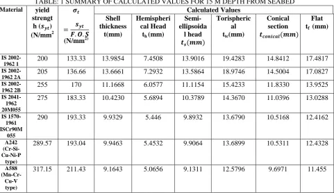
Our first step in this project is to find out the thickness of the shell and different head for particular material for particular depth. It is carried out by the design equation of marine pressure vessel using different equations. Here, the internal pressure is higher than external see water pressure. Internal diameter of the pipe is 1600 mm and the value of maximum allowable tensile stress for all the materials is taken as per standard data, by this we can calculate the thickness and outer diameter of the pressure vessels for given material. Now calculation of thickness of shell and different head at different depth of sea. In this process we have done manual calculation. Also to solve number of iterations, MATLAB programming is used.
The following results are obtained from analytical data. In this calculation of pressure vessel following parameter is taken,
Di = 1000 mm, Height ( Depth from seabed ) = 12 to 18 m.
Here for analysis purpose total seven standard alloy steel material, five from Indian standard and two American standard with their allowable yield strength value is taken. As per above formulation and flowchart we can get shell and different head thicknesses for different material.
TABLE: 1 SUMMARY OF CALCULATED VALUES FOR 15 M DEPTH FROM SEABED Material yield
strengt h (𝒔𝒚𝒕) (N/mm2 𝝈𝒕 = 𝒔𝒚𝒕 𝑭. 𝑶. 𝑺 (N/mm2) Calculated Values Shell thickness t(mm) Hemispheri cal Head
th (mm)
Semi-ellipsoida l head 𝒕𝒔(𝒎𝒎) Torispheric al ttc(mm)
Conical section
𝒕𝒄𝒐𝒏𝒊𝒄𝒂𝒍(𝒎𝒎)
Flat tf (mm)
IS
2002-1962 1 200 133.33 13.9854 7.4508 13.9016 19.4283 14.8412 17.4817
IS
2002-1962 2A 205 136.66 13.6661 7.2932 13.5864 18.9746 14.5004 17.0827
IS
2002-1962 2B 255 170 11.1668 6.0577 11.1154 15.4233 11.8330 13.9525
IS 2041-1962 20M055
275 183.33 10.4230 5.6894 10.3789 14.3670 11.0396 13.0288
IS 1570-1961 ISCr90M
055
290 193.33 9.9329 5.446 9.8932 13.6790 10.5168 12.4162
A242 (Cr-Si-Cu-Ni-P
type)
289.57 193.04 9.9463 5.4532 9.9064 13.6899 10.5311 12.4328
A588
(Mn-Cr-Cu-V type)
317.15 211.43 9.1643 5.0656 9.1311 12.5796 9.6971 11.455
Comparison relation graphs for 15 m heights for different head and shell thickness
FIG .7 Graph of shell& hemispherical vs yield strength 0 2 4 6 8 10 12 14 16
200 205 255 275 289.57 290 317.15
Th ic kn es s in (mm )
Yield strength (Syt) N/mm2
Shell Thickness t(mm)
Copyright to IJIRSET www.ijirset.com 2040 FIG.10 Graph of shell& conical vs yield strength
0 2 4 6 8 10 12 14 16 T h ic k n e s s in (m m )
Yield strength (Syt) N/mm2
Shell Thickness t(mm) Semi-ellipsoidal head 0 5 10 15 20 25
200 205 255 275 289.57 290 317.15
T h ic k n e s s i n (m m )
Yield strength (Syt) N/mm2
Shell Thickness t(mm) Torispherical 0 2 4 6 8 10 12 14 16 T h ic k n e s s in (m m )
Yield strength (Syt) N/mm2
Shell Thickness t(mm) Conical section FIG .8 Graph of shell& semi-ellipsoidal vs yield strength
Copyright to IJIRSET www.ijirset.com 2041 Graphs of Thickness of shell & Head Vs Depth
FIG.11 Graph of shell& head vs depth(is 2002-1962 1)
As depth of vessel to be placed increases, the thickness of shell and head also increase. The thickness of shell increase as depth because of pressure increases. The thickness of shell and semi-elipsoidal are same. In most favor of usage for IS 2002-1962 1, the semi-ellipsoidal shell will be preferred. The thickness of conical shell will be preferred. The thickness of hemispherical head is less as compared to other head so we will use hemispherical head in account of economical and strength way. For all type of materials, we get this type of graph.
V.
C
ONCLUSIONThe results are obtained from analytical data. It is said that as per theoretical information of the design of the pressure vessels, the thickness of shell and heads are increasing as depth of sea and decreasing as yield strength of material. The thickness of hemispherical head is lower than to other type of head. Also, the thickness of semi ellipsoidal is same as shell thickness for all materials.
If we want as thickness of shell and head will same, semi-ellipsoidal head and shell will use due to easy of welding due to same thickness. But hemispherical head has high strength as compare to other head. At lower depth, the flat and torispherical head will use. At medium depth, the conical head will use. If we want to place pressure vessels at more than eighteen meter depth, some time thickness of shell and head is increased due to pressure increases. If water is more salted, we will find best suited material from this type of analytical calculation. If we consider economical way, we can select hemispherical head due to high strength to low weight/thickness for any type of materials and any depth of sea.
All the above calculated values of the thicknesses for different materials and end closers of the pressure vessels are for its application in marine substation for mounting electrical equipments like transformers and protection of the same, the best material for this application is one which gives minimum thickness and economical. In our data material A588 (Mn-Cr-Cu-V type) material has allowable yield stress 317.15 N/mm2 which is highest of the all material and gives minimum thickness and hemispherical head is most popular and suitable head for our application as discussed above.
R
EFERENCES[1] Lars Eriksson , “Design and dimensioning of pressure vessel for a marine substation” Uppsala University.
0 2 4 6 8 10 12 14 16 18
12 13 14 15 16 17 18
Th
ic
kn
e
ss
(m
m
)
Ses Depth (M)
SHELL
HEMISPHERICAL
SEMI-ELLIPSOIDAL
TORISPHERICAL
CONICAL
Copyright to IJIRSET www.ijirset.com 2042
[2] Paul Buthod,“Pressure Vessel Handbook” , 10th Edition of with foreward by chemical engineering, University of Tulsa.
[3] Roger R. Brockenbrough, P.E., President R.L.Brockenbrough & Accociates , “Properties of Structural Steels and Effects of Steel Making and Fabrication” Chapter 1. Pitsburgh, Penssylvenia.
[4] R.S.Khurmi & J.K.Gupta text book of “Machine Design”, first edition, S.Chand, Eurasia Publishing house, New delhi, India. [5] V.B. Bhandari “Design of Machine Elements”, third edition McGraw-Hill Education India
.
A
CKNOLEDGEMENTWe would like to express our sincere thanks and gratitude to PROF. NITINCHANDRA R. PATEL (Department of Mechanical Engineering) of G.H.Patel College of Engineering and technology, Vallabh vidyanagar for devoting much of his presious and valuable time during the entire research work and for offering numorous suggestions and encouragement thus making this project possible.
AVINASH G. VASAVA (ENRL NO. 080110119057) JALWSH G. VASAVA (ENRL NO. 080110119059) ALPESH V. KUNAPARA (ENRL NO. 090110119013) SAVAN D. PATEL (ENRL NO. 090110119015)
B
IOGRAPHYProf. Nitinchandra R. Patel is an Assistant Professor in Mechanical Engineering department of G. H. Patel College of Engineering & technology, Vallabh vidyanagar, Gujarat, India. He completed Master degree in Machine Design in 2004 from Sardar Patel University, Vallabh vidyanagar and Bachelor degree in Mechanical Engineering in 1997 from B.V.M. Engineering College, Sardar Patel University. He has 5 years working experience in Industries and 11 years in Teaching. He is a member of ASME, Associate member of Institute of Engineers (I) and Life member of ISTE. He is also recognized as a Chartered Engineer by Institute of Engineers (I) in Mechanical Engineering Division.
Avinash Vasava is a Final year student of Bachelor degree in Mechanical Engineering department of G H. Patel college of Engineering & technology, Vallabh vidyanagar.
Jalesh Vasava is a Final year student of Bachelor degree in Mechanical Engineering department of G H. Patel college of Engineering & technology, Vallabh vidyanagar.
Alpesh Vanjibhai Kunapara is a Final year student of Bachelor degree in Mechanical Engineering department of G H. Patel college of Engineering & technology, Vallabh vidyanagar.