Design, Construction & Performance Test of a Computer
Numerical Control Machine
Arfuzzaman1*, Sayed Shafayat Hossain2, Md. Rasel Saddikur Zaman1
1Department of Mechatronics Engineering, World University of Bangladesh, Dhaka-1205.
2Department of Mechanical Engineering, Khulna University of Engineering & Technology,
Khulna-9203, Bangladesh.
*Corresponding Author Email: [email protected]
Abstract:
This paper is designed to develop a low cost and flexible device for controlling the Computer Numerical Control machine controller. The purpose of a Computer Numerical Control machine is to facilitate system to a specified computerized control, then to maintain it at that control a controlled manner machining. Using Micro controller PIC- 16F84 is one of the best way for precise control with low cost. We can complete it with the help of PLC (Programmable Logic Controller) but it’s too costly with respect to our project. By using the PIC -16F84A Micro controller technology has made it possible, practical and desirable to have the Computer numerical control included in the same instrument that is also controlling the other aspects of the equipment. At the end of the project, a prototype of microcontroller based Computer Numerical Control System will be developed.
1.
Introduction:
Computer Numerical Control (CNC) is one in
tool are controlled by means of a prepared program containing coded alphanumeric data. CNC can control
the motion of the piece of tool, the input parameter such as feed, depth of cut, speed and functions
such as turning spindle on/off, turning coolant on /off.
network link, transfers the output of the CAD/CAM program to a Machine Controller. [1][2]
Figure 1: Main Parts of a CNC System
There are some of the important constituent parts and aspects of CNC machines to be considered in designing, for example Machine structure, Guide ways, Feed drives, Spindle bearings, measuring systems. Control of a machine tool by means of stored information through the computer is known as computer Numerical controlled. The information stored in the computer can be read by automatic means and converted into electrical signals, which operate the electrically controlled servo systems. Electrically controlled servo systems permits the slides of machine tool to be driven
simultaneously and at the appropriate feeds and direction so that complex shapes can be cut, often with a single operation and without the need to reorient the work piece. Computer Numerically control can be applied to milling machines, lathe machines, grinding machines, boring machines, drilling machines.
the main controller subsystem, the pendant subsystem is able to accept jobs uploaded through a flash drive, access information incoming through one of the three communication ports that are active, and can change specified rates of speed and the direction of movement of the machine.
The framework of the system is set up by the mechanical subsystem which will allow for movement in the x, y, z axes and specify spatial limitations of any acceptable job. The main controller, pendant, and mechanical subsystems are able to interact through power provided by the motor driver subsystem. The motor driver subsystem will contain a power supply that can accept input power through an electrical outlet plug-in, provide movement independently to the x, y, z axes, and can add an extra board to power the acceleration axis. [1][2]
2.
Literature Review:
An entire manufacturing technology known as CAD/CAM has developed around the NC concept and, in addition, CNC with its powerful microprocessors and other enabling technologies proffered from the personal computing phenomenon has enabled the NC concept to branch into many variants, even a variant that is essentially record/playback. The latter of which are known in the industry as "teach lathes".
In addition, powerful and well-crafted human/machine interfaces allow the machine operator to prepare programs by means of interactive displays which request only the definition of the machining operation and its required parameters (such as a "pocket" and its dimensions) and not the actual tool paths with all the calculations that are there required. Anyone who knows machining concepts and blueprint interpretation can produce programs at the machine without the need for CAD/CAM. Nonetheless, the vast majority of programs are now produced with the aid of CAD/CAM and, for most users, CNC today (for all its gigahertz microprocessors and megabytes of real time kernel software) is conceptually little different from the first NC demonstrated by MIT in 1952.
Basic CNC Principles:
All computer controlled machines are able to accurately and repeatedly control motion in various directions. Each of these directions of
motion is called an axis. Depending on the machine type there are commonly two to five axes. Additionally, a CNC axis may be either a linear axis in which movement is in a straight line, or a rotary axis with motion following a circular path.
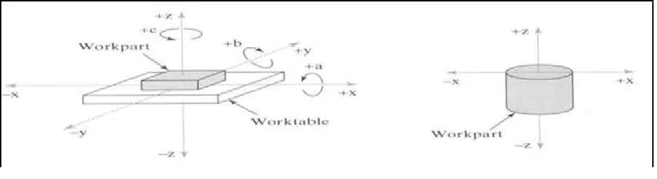
Figure 2: Coordinate system used in NC: (a)for flat and prismatic work (b)rotational work
Modern CNC Machine:
Modern CNC machines offer increased productivity due to stiffer machine and spindle designs, more powerful motors, high pressure coolant (up to 1000 psi) that floods
the cutting zone, automatic tool changers, digital work piece and tool probing, and/or horizontally mounted spindles. [4]
Figure 3: Modern CNC Machine
3.
Methodology & Construction:
The design and construction of Computer Numerically Controlled (CNC) machines differs greatly from that of conventional
machine tools. The CNC machines often employ the various mechatronics elements that have been developed over the years. There are some of the important constituents parts and aspects of CNC machines to be considered in their designing
CNC Machine Design:
The framework of the system is set up by the mechanical subsystem which will allow for movement in the x, y, z axes and specify spatial limitations of any acceptable job.
Figure 5: Isometric view of the CNC Machine (project).
The main controller, pendant, and
mechanical subsystems are able to interact through power provided by the motor driver subsystem. The motor driver subsystem will
z axes, and can add an extra board to power the acceleration axis
The overall 3D CAD diagrams of the machine are given. The CNC machine is a
system that is able to accept numerical control inputs to machine a part specified by the exact positioning of the inputs
CNC control circuit diagram:
Figure 6: Schematic Diagram of the one axis CNC Controller.
This is a one axis stepper motor controller. In this circuit one 16F84A MCU is used with 4 MHz Oscillator. ULN2003A is used for switching for the sequence of pulses for the stepper motor. The stepper motor is connected with the output of the ULN2003A. The common terminal of the ULN and the stepper is connected with motor supply
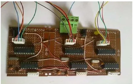
CNC machine controlling circuit:
Figure 7: CNC controller circuit.
As per our circuit design we made this controller circuit. We used our Mechatronics Lab to fabricate this circuit.
Components of project:
SI No. Name of Components Quantity
1 Microcontroller PIC16F84 03 Pcs.
2 IC(ULN 2003a) 03 Pcs.
3 Bipolar Stepper Motor 03 Pcs.
5 Wire Connector Rails (12 slots) 03 Pcs.
6 Oscillator 4MHz 05 Pcs
7 Connecting wire 01 Meter
8 PCB Board 03 Pcs.
9 Resistors,4.7k 10 Pcs
10 Thread Rod 3M
11 Square bar 3 pcs
12 Plastic Base Board for Structure (12X18’’)
7pcs
13 Bearing 3pcs
14 Transparent Plastic Board 1 pcs
15 Bearing Block 6 pcs
17 Nut & Bolt (15x6mm)
50pcs
Description of works:
After selecting the project design we tried to fabricate it with MS plate and faced some difficulties such as over weight of Machine structure. We assumed that from thumb rule our selected stepper Motor could not carry the load. The works took long time because we had to erect the job from deferent workshops. Then our thesis supervisor sir
Figure 8: Assembling the CNC Machine.
After arranging all the required materials we started to fabricate all the parts of the CNC machine. We used Steel ruler, Steel measuring tap, digital Vernier Caliper to take
Figure 9: CNC machine (under construction).
We designed and made the bearing Block several times because when bearing is to set into the block it should be completely fit with outer. For assembling the stepper motor with the lead screw throw the bearing we used two pieces square shaped transparent plate. All of assembling works we did at our mechatronics lab. For joining the parts we used different sizes of screws.
After completing the X axis portion the CNC machine we checked with our control either
it works or not. As per working principle of the CNC machines when stepper motor rotates then tool post move on the slider. But the slide could not move easily due to unparalleled alignment. Then we corrected it. With the same working procedure we completed Y-axis potion of the CNC machine. Then we checked and tested X-Y axis potion at a time and found it as it was working in order. We assembled the Z-axis portion also. But when we joined it with base machine then we found some problems. The machine got tilted. The parts of the slider and supports would have required rigid bars.
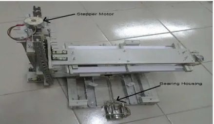
Figure 10: Completed CNC Machine.
After completion weight of the different parts of different positions became unbalanced.
found some positions are little bit inclined from right position. So we should have used heavier part for Base and horizontal (X) portions, lighter part for vertical (Y) portion and competitively lighter parts for top (Z)
portion where tool is to be mounted. Some of points we could use extra support of thin MS flat (3mm) bar to prevent the inclination of the plastic frames.
Firmware of the One Axis CNC Controller [6][7][8]
'Firmware for CNC Machine Controller in PIC Basic of PIC Simulator IDE 'Developed by Arfuzzaman,
'(c) Arfuzzaman 2014
'By default, this program will use RA0 , RA1 , RA2, RA3 as Stepper motor output for 0,1,2,3 bits of unipolar stepper motor
'RB0 = Step input used as interrupt pin 'RB1 = Enable
'RB2 = Clockwise(High)/Anticlockwise(low) Direction 'RB3 = Full(high)/Half(low) step
TRISB = 0xff 'set all PORTA pins as inputs TRISA = 0x00 'set all PORTA pins as outputs INTCON.INTE = 1 'enable RB0/INT interrupts INTCON.GIE = 1 'enable all un-masked interrupts
Dim seq1(8) As Byte Dim seq2(8) As Byte Dim index As Byte Dim checkstate As Byte
seq1(0) = %00001010 seq1(1) = %00001001 seq1(2) = %00000101 seq1(3) = %00000110
seq2(0) = %00001010 seq2(1) = %00001000 seq2(2) = %00001001 seq2(3) = %00000001 seq2(4) = %00000101 seq2(5) = %00000100 seq2(6) = %00000110 seq2(7) = %00000010
index = 0
checkstate = 0 'Half Step RA = seq1(0)
start:
If RB1 Then 'enable
If RB3 Then 'Full step If checkstate = 0 Then
checkstate = 1 If(index) Then
index = index / 2 Endif
Endif
RA = seq1(index) Else 'Half step
If checkstate = 1 Then checkstate = 0 If(index) Then
index = 2 * index Endif
Endif
RA = seq2(index) Endif
Endif
Goto start
End
On Interrupt 'interrupt routine If RB1 Then 'enable
If RB2 Then 'direction clockwise index = index + 1
If RB3 Then 'full step If index > 3 Then
index = 0 Endif
Else 'Half Step
If index > 7 Then index = 0 Endif
Endif
Else 'direction anticlockwise If index > 0 Then
index = index - 1 Else
If RB3 Then 'Full step index = 3
Else 'Half Step index = 7 Endif
Endif Endif
4. Results & Discussion:
After building the project we were testing the CNC machine. Our project objective first is to design the CNC machine using microcontroller with accurate input and output pin. The working components such as stepper motors and other device are connected with the microcontroller. The program in the microcontroller is written by PICKit-2.
Our second objective is to construction a CNC machine which can work as a usual CNC machine. Our thesis project CNC machine is similar to the usual CNC machine and is small that can operate like usual CNC machine but the area of the machining is limited. CNC machine is all about using the computer as a means to control machines that carves useful objects from solid block to material.
During testing we found that the full machine became unbalanced because of flexible and soft slide ways. Because of that the device was tiled on one side. Due to that it was not
tested for motion. Also the controller circuit is not made properly. Therefore the controller could not be checked at all. Theoretically the schematic and the firmware are perfect to operate with CNC software. Also selecting proper values for machining parameters such as cutting speed, feed rate, and depth of cut directly affects the machining economics in metal cutting process by the CNC software. Several cutting constraints must be considered in machining operations. In turning operations, a cutting process can possibly be complicated with a single pass or by multiple passes. Multi pass turning is preferable over single pass turning in the industry for economic reasons. That makes the problem of determining the optimal cutting conditions more difficult and complicated. Machining parameters can be determined based on machine operator’s experience or by following the cutting handbook supplied by the equipment manufacturer. However, those data are not guaranteed to be optimal or even good for a particular cutting environment.
In the lab we tried to test the controller with the following logics and checked the outputs.
Full Steps
Seq-0 RA3 RA2 RA1 RA0 Forward Reverse
Seq-1 0 0 0 1 1 0
Seq-2 0 0 1 0 1 0
Seq-3 0 1 0 0 0 1
Seq-4 1 0 0 0 0 1
Half Steps
Seq-1 0 0 0 1 1 0
Seq-3 0 1 0 0 1 0
Seq-4 1 0 0 0 1 0
Seq-5 0 0 0 1 0 1
Seq-6 1 0 1 0 0 1
Seq-7 1 0 1 1 0 1
Seq-8 1 1 0 0 0 1
Mach3 is a powerful application that can help CNC machine operators to send commands in order to complete their projects. It was developed as a program for hobbyists but it can also be implemented by companies and industrial users
The program intends to transform any computer into a CNC machine controller, able to send commands to a 6 axis cutter. It can import data from DXF, BMP, JPG or G-code files in order to control the device.
Figure 11: The Mach3 Software for CNC
5. Conclusion
We gathered huge of knowledge on mechatronics and its integration with software. We have already got an idea of computer numerical control and its application & implementation. We tried to make a CNC machine. The machine was
cheapest possible parts. The controller and motors were also obtained from local shops.
more confident on practice basis, where we felt as if we were working with this equipment for a long time. Though the machine could not be tested properly but it gave us basic idea about CNC machine’s working principle, design and construction.
Working as a Team in this project contributed in our success, because we all were not familiar with every aspect of the requirements. One of us was good with programming, two with the Mechanical part and fabrications as with the machine and one with hardware as in the controlling circuit. Logical thinking is a very important aspect to build any circuit that has no idea of what environment it is going to deal with, and this aspect was in all four of us.
We always though in a problem logically first, worked on that logic. So we distributed our works within ourselves. By doing this project together we ended up getting knowledge and information on the areas we were weak in through sharing ideas and thoughts with each other. We had to modify lots of things such as circuit, program, Machine frames, motors, bearings and housings. During building this project we used different type hand tools. At last we were able to overcome by little bit modifications and readjustments. Finally we carried out project works quite successfully.
Future Recommendations:
• The CNC machine can be made with aluminum or steel frame.
• Different controlling approaches can be used.
• Machine can be designed more accurately to be balanced with frame loads by load analyses.
• The machine can be made with more precious and accurate stepper motors.
References:
[1] Abderrahim, M. & Whittaker, A. R. (2000)., Kinematic Model Identification of Industrial Manipulators, CNC Machine and Computer-Integrated Manufacturing, Vol. 16, No.1, February 2000, pp 1-8.
[2] Cheng, S. F. (2007). The Method of Recovering TCP Positions in Industrial Robot Production Programs, Proceedings of 2007 IEEE International Conference on Mechatronics and Automation, August 2007, pp. 805-810.
[3] en.wikipedia.org/wiki/Numerical control. [4] http://www.iitk.ac.in/infocell/TA201N20 12/cncforwebsite.pdf [5] https://en.wikipedia.org/wiki/ULN2003 A [6] www.udemy.com/cnc-programming-for-beginners/ [7] www.lynda.com/Developer-training-tutorials/50-0.html
Biography of Authors:
Arfuzzaman achieved B.Sc. in Mechatronics Engineering degree from World University of Bangladesh with 1st div. He had several projects related to bio-electromechanical engineering, Automobile Engineering, Automation & Robotics, Production & Manufacturing Engineering, Digital Logic Circuit & Microprocessors etc. His future research interests include “Advanced Mechatronics Engineering”. Email: [email protected]
Sayed Shafayat Hossain achievedB.Sc.in MechanicalEngineering degree from Khulna University of Engineering & Technology (KUET) with 1st div. He got technical scholarship throughout all semesters. He had numerous projects during his graduation period & most significant projects are related to Automobile, Heat Transfer, Advanced Metallurgy, Solid Works Design, Matlab Projects and so on. In future his research interests include Manufacturing Engineering & Advanced Material Science. Email: [email protected]