Western University Western University
Scholarship@Western
Scholarship@Western
Electronic Thesis and Dissertation Repository
9-11-2013 12:00 AM
Development and Applications of a Novel Intermittent Solids
Development and Applications of a Novel Intermittent Solids
Feeder for Pyrolysis Reactors
Feeder for Pyrolysis Reactors
Federico M. BerrutiThe University of Western Ontario
Supervisor
Dr. Cedric L. Briens
The University of Western Ontario
Graduate Program in Chemical and Biochemical Engineering
A thesis submitted in partial fulfillment of the requirements for the degree in Doctor of Philosophy
© Federico M. Berruti 2013
Follow this and additional works at: https://ir.lib.uwo.ca/etd
Part of the Transport Phenomena Commons
Recommended Citation Recommended Citation
Berruti, Federico M., "Development and Applications of a Novel Intermittent Solids Feeder for Pyrolysis Reactors" (2013). Electronic Thesis and Dissertation Repository. 1617.
https://ir.lib.uwo.ca/etd/1617
This Dissertation/Thesis is brought to you for free and open access by Scholarship@Western. It has been accepted for inclusion in Electronic Thesis and Dissertation Repository by an authorized administrator of
DEVELOPMENT AND APPLICATIONS OF A NOVEL
INTERMITTENT SOLIDS FEEDER FOR PYROLYSIS
REACTORS
(Thesis format: Integrated-Article)
by
Federico M. Berruti
Graduate Program in Engineering Science Department of Chemical & Biochemical Engineering
A thesis submitted in partial fulfillment of the requirements for the degree of
Doctor of Philosophy
The School of Graduate and Postdoctoral Studies The University of Western Ontario
London, Ontario, Canada July 2013
ii
Abstract
This PhD research addresses the challenge of feeding biomass residues into fluidized
bed reactors for pyrolysis, through the development of a novel intermittent solid slug
feeder, both for laboratory-scale and large-scale reactors. The new feeder can
successfully handle biomass residues that are either too cohesive or thermally sensitive
for traditional feeders.
To optimize the novel feeder performance, a model for the pulsating solids flow was
developed from experimental data collected with ideal slugs, as well as real biomass
flow. The model was validated using both a laboratory-scale (< 10 kg/hr) and large-scale
feeder (> 250 kg/hr). Several important variables were identified. They include the
material flow properties, the pulse gas pressure and volume, and the feeding tube
length and material. The goals of this study were to (a) characterize the fundamental
dynamic behavior of the biomass slugs in the feeder, (b) maximize the solid-to-gas
feeding ratio, and thus minimize energy consumption and cost, (c) minimize the
accumulation of “straggler” biomass material in the feeding tube between pulses, and
thus prevent biomass heating in the feeding tube, which can induce plugging, and (d)
develop and validate a predictive model for the slug velocity at any location in the
feeding tube, which can be applied to feeder design for any biomass feedstock.
An advantage of the new large-scale feeder technology is that it can handle larger
biomass particles than traditional feeder technologies. An issue with large particles is
iii
therefore developed for drying, which takes shrinkage, and internal and external mass
transfer limitations into account.
The thesis is supplemented with additional work based on the application of the novel
feeder for pyrolysis studies with various biomass residues. The feeder technology made
it possible to perform the first ever pyrolysis studies, in industrially-relevant equipment,
on pure meat and bone meal residue, and on unmodified and undiluted Kraft lignin.
Appendices include a business case-study of the implementation of the technologies
developed in this thesis on large-scale pyrolysis and an additional pyrolysis study on
tucumã seeds, which utilized the novel feeder.
Keywords
Feeder, feed rate, injection, powder, pulsations, slugs, cohesive, temperature-sensitive,
granules, feedstock, biomass, agricultural residue, forestry residue, pyrolysis,
gasification, fluidized bed, oil, bio-oil, bio-char, biochar, dried distiller’s grains, meat and
iv
Co-Authorship Statement
Chapters 1 through 6, and Appendix I and II, encompass research studies which have
been published or submitted to peer-refereed journals. Individual contributions of all
authors for each publication are summarized below.
CHAPTER 1
This chapter incorporates sections of the two following published papers:
Article Title Novel Fluid Bed Pilot Plant for the Production of Bio-oil from Biomass through Fast Pyrolysis.
Authors F.M. Berruti, K. Lenkiewicz, R. Xu, R.J. Bedmutha, S. Nova, F. Berruti, C. Briens
Current Status Published in Récents Progrès en Génie des Procédés, Numéro 94 – 2007, ISBN 2-910239-68-3, Ed. SFGP, Paris, France.
F.M. Berruti and K. Lenkiewicz conducted the literature review, the reactor assembly, the experimental work, the data analysis and F.M. Berruti wrote the manuscript. R. Xu and R.J. Bedmutha performed supplemental experimental work and some chemical analysis. The experimental work was supervised by S. Nova. C. Briens and F. Berruti jointly supervised, reviewed and revised several drafts of the work.
Article Title Biomass residue fast pyrolysis: the future outlook
Authors F.M. Berruti
Current Status Published in the Canadian Biomass Magazine, 2013
(http://www.canadianbiomassmagazine.ca/content/view/3954/133/) F.M. Berruti conducted the literature review and wrote the manuscript.
CHAPTER 2
Article Title Preliminary Design and Optimization of an Intermittent Slug Injection System for Sawdust Biomass Pyrolysis
Authors F.M. Berruti, L. Ferrante, F. Berruti, C. Briens
Current Status Published in the International Journal of Chemical Reactor Engineering, Volume 7, 2009, A84.
v CHAPTER 3
Article Title Novel intermittent solid slug feeder for fast pyrolysis reactors: fundamentals and modelling
Authors F.M. Berruti, C. Briens
Current Status Published in Powder Technology 247, 2013, 95-105.
F.M. Berruti performed the literature review, equipment design and assembly, experimental work, data analysis, modelling and wrote the manuscript. C. Briens supervised, reviewed and revised several drafts of the work.
CHAPTER 4
Article Title Novel intermittent solid slug feeder for fast pyrolysis reactors: Scale-up, alternate geometries, and feeder design procedure
Authors F.M. Berruti, C. Briens
Current Status Currently Unpublished Work.
F.M. Berruti performed the literature review, equipment design and assembly, experimental work, data analysis, modelling and wrote the manuscript. C. Briens supervised, reviewed and revised several drafts of the work.
CHAPTER 5
Article Title Model for convective drying of carrots for pyrolysis Authors F.M. Berruti, M. Klaas, C. Briens, F. Berruti
vi CHAPTER 6
Article Title Pyrolysis of cohesive meat and bone meal in a bubbling fluidized bed with an intermittent solid slug feeder
Authors F.M. Berruti, L. Ferrante, C. Briens, F. Berruti
Current Status Published in the Journal of Analytical and Applied Pyrolysis, 94, 2012, 153-162.
F.M. Berruti performed the literature review, apparatus and reactor assembly and
modifications, experimental work and data analysis and wrote the manuscript. L. Ferrante supervised the experimental work and a portion of the data analysis (GC-MS). C. Briens and F. Berruti jointly supervised, reviewed and revised several drafts of the work.
APPENDIX I
Article Title Green-Tech: Bio-Fuels High Growth Strategy (Case and Teaching Note)
Authors F.M. Berruti, Heng-Yih (Gordon) Liu
Current Status Published by Ivey Publishing (9B11M123 and 8B11M123), 2012 F.M. Berruti and Heng-Yih (Gordon) Liu jointly wrote the case and teaching note.
APPENDIX II
Article Title Fast pyrolysis of Amazon tucumã (Astrocaryum aculeatum) seeds in a bubbling fluidized bed reactor
Authors C. Lira, F.M. Berruti, P. Palmisano, F. Berruti, C. Briens, A.A.B. Pécora Current Status Published in the Journal of Analytical and Applied Pyrolysis, 99, 2013,
23-31.
vii APPENDIX III
Article Title Kraft Lignin Pyrolysis in a Fluidized Bed Reactor Authors P. Palmisano, F.M. Berruti, V. Lago, F. Berruti, C. Briens Current Status Published at TCBiomass 2011, Chicago, Illinois, USA
viii
Acknowledgments
Firstly, I would like to extend my deepest appreciation and gratitude to my brilliant
supervisor, Dr. Cedric Briens. Cedric has always been outstanding in his role as my
supervisor, providing continuous encouragement, constructive criticism, technical skill,
guidance, trust and understanding throughout my doctoral studies. What is even better
is that from great “supervisor”, Cedric is now also my friend, mentor and colleague, who
I hope to continue to have the privilege to work with in the future.
I also wish to extend my gratitude to my great colleagues and friends at ICFAR who I
have worked with along the way, especially Dr. Lorenzo Ferrante, Dr. Ran Xu, Dr. Pietro
Palmisano, Martin Huard, Claudio Lira, Matthew Klaas, Craig Mara, and Rob Taylor. I
greatly appreciate their suggestions, help, work and conversations at various stages of
my thesis, and most importantly, their friendship.
My gratitude is also extended to the Ontario Centres of Excellence (OCE), the Natural
Sciences and Engineering Research Council of Canada (NSERC) Vanier Canada Graduate
Scholarship program, the great team at Agri-Therm Ltd. who I have loved working with,
and Western University for the financial support of the research program. I gratefully
acknowledge the Faculty of Engineering at Western University for the financial support
in the forms of Western Engineering Scholarships (WES) and Graduate Thesis Research
Awards (GTRA).
I would also like to acknowledge the University Machine Services (UMS), Information
ix
Moreover, the valuable time, advice and assistance from Clayton Cook, Souheil Afara,
Brian Dennis, and Eugen Porter is greatly appreciated.
Last, but certainly not least, I would like to thank my parents, Franco and Alessandra
Berruti, my close friend, Valter Feyles, and my partner, Meg Atkinson, for their
incredible love, patience, guidance and support for me to have my opportunities and
achieve my goals.
I am very close to my parents, in particular to my mother, Alessandra. Her love, energy
and thoughtful nurturing have made me the happy and confident person I am today,
and I will continue to cherish her love and inspiring ideas and advice throughout my life.
I have also had the amazing privilege of working alongside my father, Dr. Franco Berruti,
for various projects over these great years. It goes without saying that his energy,
vision, sincerity, creativity, curiosity and honour is appreciated by everyone who
x
Dedications
For my outstanding, supportive and unconditionally-loving parents, Franco and
Alessandra Berruti, and for my great supporter and friend, Valter Feyles, without whom
none of this would be remotely possible.
For my incredible, supportive, loving and understanding partner, Meg Atkinson, who
inspires me to be my curious self and to love every moment of this life.
In memory of my grandfathers, Cornelio Berruti and Agostino Gianetto.
xi
Table of Contents
Abstract ... ii
Co-Authorship Statement... iv
Acknowledgments... viii
Dedications ... x
List of Tables ... xviii
List of Figures ... xx
Key Abbreviations ... xxvi
Chapter 1 ... 1
1 Chapter 1: Introduction ... 1
1.1 Introduction & Background ... 1
1.2 Introduction to Biomass Pyrolysis ... 4
1.3 Environmental Benefits of Pyrolysis ... 6
1.4 Types of Pyrolysis... 7
1.5 Bio-oil Product Overview ... 9
1.5.1 Description and Properties ... 9
1.5.2 Bio-oil Applications and Upgrading ... 12
1.6 Pyrolysis Reactor Technologies ... 13
1.6.1 Fluidized Bed Reactor... 14
1.6.2 Ablative Reactor ... 19
1.6.3 Rotating Cone Reactor ... 20
1.6.4 Vacuum Reactor... 22
1.6.5 Auger Reactor ... 23
xii
1.8 The Future Outlook of Biomass Fast Pyrolysis [38] ... 28
1.9 Reactor Feeding Technology ... 33
1.9.1 Dilute-Phase Pneumatic Feeders... 33
1.9.2 Screw/Auger Feeders ... 33
1.9.3 Novel ICFAR Intermittent Solid Slug Feeder ... 34
1.9.4 Dense-Phase Pneumatic Feeders... 35
1.10Thesis Objectives & Outline ... 36
1.11References ... 38
Chapter 2 ... 45
2 Chapter 2: Preliminary Design and Optimization of a Lab-Scale Intermittent Solid Slug Feeder ... 45
2.1 Introduction ... 45
2.2 Experimental Procedure ... 48
2.2.1 Equipment Description ... 48
2.2.2 Variable Definition ... 51
2.2.3 Procedure ... 52
2.3 Results and Discussion ... 53
2.4 Conclusions and Recommendations ... 61
2.5 Acknowledgements ... 61
2.6 References ... 62
Chapter 3 ... 63
3 Chapter 3: Novel Intermittent Solid Slug Feeder for Fast Pyrolysis: Fundamentals and Modelling ... 63
3.1 Introduction ... 63
3.2 Materials and Methods ... 65
xiii
3.2.2 Materials and Feedstocks ... 68
3.3 Fundamental Operation Results and Discussion... 70
3.3.1 Feeder Operating Conditions and Feeding Rate ... 70
3.3.2 Flowrate-of-Solids to Flowrate-of-Gas Ratio ... 72
3.3.3 Effect of Pulse Pressure on Feeding Rate ... 74
3.3.4 Effect of Mixer RPM on Feeding Rate ... 75
3.3.5 Effect of Pulse Pressure on Straggler Accumulation ... 76
3.3.6 Effect of Pulse Pressure on Slug Spreading during Motion ... 77
3.4 Feeder Modelling Results & Discussion... 79
3.4.1 Modelling Approach and Objectives ... 79
3.4.2 Model Equations ... 82
3.4.3 Modelling Pulse Gas Flow through Orifice ... 86
3.4.4 Modelling the Static Solid Ball ... 88
3.4.5 Modelling the Dynamic Solid Ball Projectile ... 90
3.4.6 Modelling Dynamic Dried Distillers’ Grain Slug ... 92
3.4.7 Friction Factor and the Fully Predictive Model ... 95
3.4.8 Model Utilization and Design Criteria ... 100
3.5 Conclusions ... 101
3.6 Acknowledgements ... 102
3.7 Notation... 103
References ... 104
Chapter 4 ... 106
4 Chapter 4: Novel Intermittent Solid Slug Feeder for Fast Pyrolysis Reactors: Application of Predictive Model for Scale-Up, Alternate Geometries, and Optimized Feeder Design Procedure ... 106
xiv
4.2 Materials and Methods ... 109
4.2.1 The ICFAR Intermittent Solid Slug Feeding Technology ... 109
4.2.2 Materials and Feedstocks ... 114
4.3 Results and Discussion ... 116
4.3.1 Maximum Solid Flowrate for the Large-Scale Feeder ... 116
4.3.2 Modelling Approach and Objectives ... 117
4.3.3 Predictive Model ... 120
4.3.4 Determination of the Empirical Model Parameters ... 127
4.3.5 Validation of Model on Large-Scale Feeder with DDG and MBM ... 130
4.3.6 Slug Chamber Geometry Design Improvements & Design Procedure .. 133
4.3.7 Additional Feeder Design Considerations ... 140
4.4 Conclusions ... 141
4.5 Acknowledgements ... 141
4.6 Notation... 142
4.7 References ... 143
Chapter 5 ... 145
5 Chapter 5: Feed Preparation and Model for Convective Drying of Carrots for Pyrolysis ... 145
5.1 Introduction ... 145
5.2 Mathematical Modelling ... 148
5.3 Materials and Methods ... 156
5.4 Results and Discussion ... 157
5.5 Conclusion ... 165
5.6 Acknowledgements ... 166
5.7 References ... 167
xv
6 Chapter 6: Pyrolysis of Cohesive Meat and Bone Meal Residues in a
Laboratory-Scale Bubbling Fluidized Bed Reactor using an Intermittent Solid Slug Feeder ... 169
6.1 Introduction ... 169
6.2 Materials and Methods ... 174
6.2.1 The Feedstock ... 174
6.2.2 ICFAR Laboratory-Scale Bubbling Fluidized Bed Pyrolysis Pilot Plant 175 6.2.3 Analysis of Products ... 178
6.2.4 The ICFAR Intermittent Solid Slug Feeder Technology ... 179
6.2.5 Heat of Pyrolysis Methodology and Equipment ... 182
6.3 Results and Discussion ... 187
6.3.1 Effect of Temperature on Product Yields ... 187
6.3.2 Bio-oil Product Properties... 189
6.3.3 Gas Product Properties ... 193
6.3.4 Bio-char Properties ... 194
6.3.5 Heat of Pyrolysis ... 195
6.3.6 Energy Balance and Process Thermal Sustainability... 196
6.4 Conclusions ... 200
6.5 Acknowledgements ... 201
6.6 References ... 202
Chapter 7 ... 205
7 Chapter 7: Conclusions and Recommendations ... 205
7.1 Conclusions and Highlights ... 205
7.2 Recommendations ... 210
Appendix I ... 213
xvi
8.1 Introduction ... 213
8.2 Green-Tech Inc. ... 213
8.3 The Core Product & Technology: THE MPT1 ... 214
8.4 New Market, Product Availability and Research & Development ... 217
8.5 MPT Costing & Business Model ... 220
8.6 Other Products & Business Opportunities ... 221
8.7 Customer Selection ... 222
8.8 Competitors ... 223
8.9 Future Challenges & Decisions ... 225
8.10TEACHING NOTE ... 232
8.11Case Synopsis ... 232
8.12Key Words ... 233
8.13Potential Audience and Instructor’s Material ... 233
8.14Teaching Objectives... 234
8.15Suggested Assignment Questions ... 234
8.16Analysis... 235
8.17Additional Possible Discussion Questions ... 238
8.18Other Key Points of Discussion ... 241
8.19What Bruteque Actually Recommended ... 243
8.20Conclusion ... 245
Appendix II ... 252
9 Appendix II: Fast Pyrolysis of Amazon Tucumã (Astrocaryum aculeatum) Seeds in a Bubbling Fluidized Bed Reactor ... 252
9.1 Introduction ... 252
xvii
9.2.1 The ICFAR Laboratory-Scale Bubbling Fluidized Bed Pyrolysis Pilot
Plant ... 258
9.2.2 The Feedstock and Materials ... 261
9.2.3 Methodology ... 262
9.3 Results and Discussion ... 265
9.3.1 Effect of Temperature on Product Yields ... 265
9.3.2 Effect of Temperature on Bio-oil Properties ... 266
9.3.3 Effect of Temperature on Gas Properties ... 273
9.3.4 Effect of Temperature on Biochar Properties ... 274
9.3.5 Energy Balance ... 277
9.4 Conclusions ... 280
9.5 Acknowledgements ... 280
9.6 References ... 282
Appendix III ... 286
xviii
List of Tables
Table 1-1: Types of Pyrolysis [8] ... 8
Table 1-2: Products from Bio-oil ... 13
Table 1-3: Advantages and Drawbacks of the BFB... 17
Table 1-4: Advantages and Drawbacks of the CFB... 18
Table 1-5: Advantages and Drawbacks of the Ablative Reactor ... 20
Table 1-6: Advantages and Drawbacks of the Rotating Cone Reactor ... 21
Table 1-7: Advantages and Drawbacks of the Vacuum Reactor ... 23
Table 1-8: Advantages and Drawbacks of the Auger Reactor ... 24
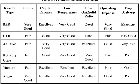
Table 1-9: Reactor Selection Criteria ... 27
Table 3-1: Feedstock Properties... 70
Table 3-2: Solenoid Valve Flow Coefficient ... 87
Table 3-3: Static Ball Flow Coefficient ... 89
Table 4-1: Feedstock Properties... 115
Table 5-1: Summary of calculated initial effective diffusivities for all experiments using the Henderson and Pabis model ... 163
Table 5-2: Summary of results provided by the Crank computational model ... 163
Table 6-1: Meat and Bone Meal Specifications ... 175
xix
Table 6-3: Organic Compounds Detected in a Bio-oil Sample Produced at 550C and their
Corresponding Chemical Families ... 192
Table 6-4: Micro GC Analysis of Non-Condensable Gas Produced by Pyrolysis of MBM ... 193
Table 6-5: Raw MBM and MBM Bio-char Ash Analysis ... 195
Table 9-1: Physical and Chemical Properties of Tucumã Seeds ... 261
Table 9-2: Gas Flowrate for the Fluidized Bed Reactor ... 262
Table 9-3: Bio-oil Proximate Analysis ... 269
Table 9-4: Bio-oil's pH Variation with Production Temperature ... 269
Table 9-5: Main Peak Compounds in Bio-oil from GC-MS Analysis... 272
xx
List of Figures
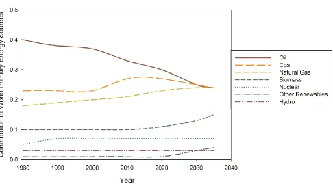
Figure 1-1: Contribution of World Primary Energy Sources... 3
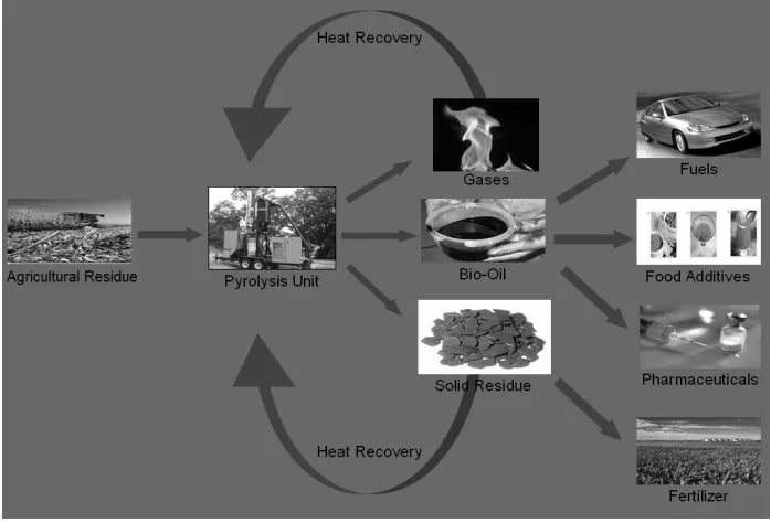
Figure 1-2: Pyrolysis Process Chart ... 5
Figure 1-3: BFB Reactor Technology... 16
Figure 1-4: Circulating Fluidized Bed Reactor Technology... 18
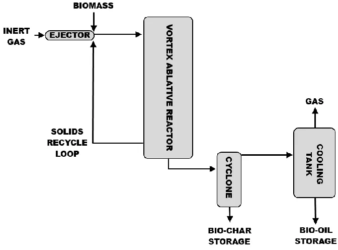
Figure 1-5: Ablative Reactor Technology ... 19
Figure 1-6: Rotating Cone Reactor Technology [34] ... 21
Figure 1-7: Vacuum Reactor Technology ... 22
Figure 1-8: Auger Reactor Technology ... 24
Figure 2-1: ICFAR Novel Feeder Installed on Full Reactor Setup ... 50
Figure 2-2: Intermittent Solid Slug Feeder Experimental Apparatus ... 51
Figure 2-3: Calculated critical mass of air required to clear feeding tube vs. number of capacitance canisters at Δtopen = 2 s and continuous mass flowrate = 0.25 g/s ... 55
Figure 2-4: Effect of continuous air mass flowrate on sawdust mass flowrate ... 56
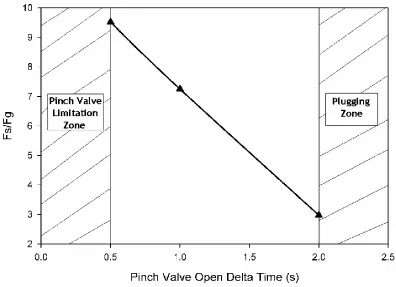
Figure 2-5: Slug chamber illustrations at different pinch valve Δtopen values ... 57
Figure 2-6: Calculated maximum Experimental Fs/Fg vs. Pinch Valve Δtopen values ... 59
Figure 3-1: ICFAR Intermittent Solid Slug Feeder Schematic ... 67
Figure 3-2: DDG Feeding Rate ... 71
Figure 3-3: MBM Feeding Rate ... 71
xxi
Figure 3-5: MBM Solids-to-Gas Flowrate Ratio vs. Pulse Pressure ... 73
Figure 3-6: Effect of Pulse Pressure on DDG Feeding Rate ... 74
Figure 3-7: Effet of Mixer RPM on DDG Feeding Rate. P = 308 kPa. ... 76
Figure 3-8: Effect of Pulse Pressure on DDG Straggler Accumulation. L = 1.12 m, ID =
0.0127 m. ... 77
Figure 3-9: Effect of Pressure on DDG Slug Length Spreading ... 78
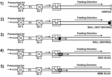
Figure 3-10: Step-Wise Modelling Approach... 82
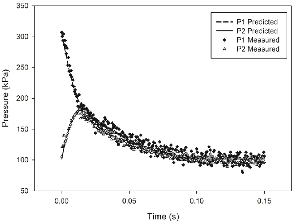
Figure 3-11: Measured and Predicted Pressure Curves for Orifice Pulse Flow ... 88
Figure 3-12: Measured and Predicted Pressure Curves for Static Ball Pulse Flow ... 89
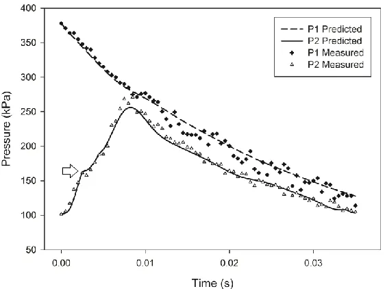
Figure 3-13: Measured and Predicted Pressure Curves for Dynamic Ball Projectile Pulse
Flow ... 91
Figure 3-14: Predicted and Measured Dynamic Ball Position vs. Time ... 92
Figure 3-15: Measured and Predicted Pressure Curves for Dynamic DDG Slug Pulse
Flow ... 94
Figure 3-16: Predicted and Measured Dynamic DDG Slug Position vs. Time ... 95
Figure 3-17: Friction Factor vs. Shoulder Critical Pressure Index for Feedstocks ... 97
Figure 3-18: Shoulder Critical Pressure vs. Pulse Pressure for Feedstocks ... 97
Figure 3-19: Predictive Model - Ball Position vs. Time at Different Pulse Pressures... 99
Figure 3-20: Predictive Model - DDG Slug Position vs. Time at Different Pulse Pressures
... 99
Figure 3-21: Predictive Model - MBM Slug Position vs. Time at Different Pulse
xxii
Figure 3-22: Predictive Model - DDG Position vs. Time at Different Capacitance
Volumes with Equal Gas Moles ... 101
Figure 4-1: ICFAR Intermittent Solid Slug Feeder Schematic (laboratory-scale and
large-scale) ... 112
Figure 4-2: ICFAR Intermittent Solid Slug Feeder Slug Chamber Designs ... 112
Figure 4-3: Maximum Achievable DDG and MBM Feeding Rate on Large-Scale Feeder
(1.8 s cycle time and 155 kPa air pulse pressure) ... 117
Figure 4-4: Modelling Approach Schematic... 120
Figure 4-5: Pressure matching to find SV3 flow coefficient for Large-Scale Feeder
(knowing feeding tube tip orifice flow coefficient of 1.718 and no solids flow) ... 128
Figure 4-6: Critical Pressure (shoulder) in Pulse Pressure Signal for DDG Slug ... 130
Figure 4-7: Predicted and Experimental Pressures of DDG Slug on Large-Scale Feeder
(ms = 0.150 kg, P1 = 210 kPa, PC = 130 kPa) ... 131
Figure 4-8: Large-Scale Feeder DDG Predictive Model (ms = 0.150 kg, PC = 130 kPa) 132
Figure 4-9: Predicted and Experimental Pressures of MBM Slug on Large-Scale Feeder
(ms = 0.130 kg, P1 = 210 kPa, PC = 122 kPa) ... 132
Figure 4-10: Large-Scale Feeder MBM Predictive Model (ms = 0.130 kg, PC = 122 kPa)
... 133
Figure 4-11: Predicted Laboratory-Scale Feeder ms/mg vs. ms Performance Curves from
Predictive Model (L = 1 m, D = 0.0153 m) ... 135
Figure 4-12: Predictive Model Difference between equivalent volume “T” and Angled
Slug Chambers (6 g DDG slug and 308 kPa air pulse)... 136
Figure 4-13: DDG Feeding Rates with Different Slug Chamber Designs (optimized 2.4 s
xxiii
Figure 4-14: Predicted Medium-Sized Theoretical Feeder ms/mg vs. ms Performance
Curves from Predictive Model (L = 1 m, D = 0.0267 m) ... 139
Figure 4-15: Predicted Large-Scale Feeder ms/mg vs. ms Performance Curves from
Predictive Model (L = 1 m, D = 0.05113 m) ... 139
Figure 5-1: Variation of moisture ratio of unaltered carrot cylinders drying under
different air speeds at 21°C ... 159
Figure 5-2: Variation of moisture ratio of unaltered carrot cylinders drying under
different temperatures at 0.95 m/s ... 159
Figure 5-3: Variation of drying rate of carrot cylinders for different carrot preparations at
21°C and 0.5 m/s ... 160
Figure 5-4: Variation of drying rate of carrot cylinders for unaltered carrots at different
air speeds at 21°C ... 160
Figure 5-5: Variation of drying rate of carrot cylinders for unaltered carrots at different
temperatures and 0.95 m/s ... 161
Figure 5-6: Drying rate vs. solid moisture content at 56°C and 0.95 m/s. ... 161
Figure 6-1: ICFAR Pilot Plant Process Flow Schematic ... 178
Figure 6-2: ICFAR Intermittent Solid Slug Feeder Schematic ... 181
Figure 6-3: ICFAR Intermittent Solid Slug Feeder - Open Air MBM Feeding Rate ... 182
Figure 6-4: Atomizing Nozzle used for Water Calibration ... 185
Figure 6-5: Power Consumption vs. Water Flowrate at Constant N2 Flowrate and
Temperature ... 185
Figure 6-6: Power Consumption vs. Temperature at Constant N2 Flowrate and Water
xxiv
Figure 6-7: Power Consumption vs. N2 Flowrate at Constant Temperature and Water
Flowrate ... 187
Figure 6-8: Product Yields vs. Temperature ... 188
Figure 6-9: Effect of Temperature on Bio-char Heating Value (HHV) ... 194
Figure 6-10: Heat of Pyrolysis vs. Temperature ... 196
Figure 6-11: Energy Sustainability Schematic ... 199
Figure 6-12: Comparison of Net Captured Product Energy and Raw MBM Energy vs.
Temperature ... 200
Figure 8-1: EXHBIT 1 - The Fast Pyrolysis Process ... 226
Figure 8-2: EXHIBIT 2 - Green-Tech's Mobile Pyrolysis System ... 227
Figure 8-3: EXHIBIT 3 - Business Opportunities ... 228
Figure 8-4: EXHIBIT 4 - MPT Economic Considerations for Green-Tech Clients ... 229
Figure 8-5: EXHIBIT 5 - Income Statement - Year Ending April 30, 2011 (CDN$) .... 230
Figure 8-6: EXHIBIT 6 - Balance Sheet - Year Ending April 30, 2011 (CDN$) ... 231
Figure 9-1: Process Flow Diagram of ICFAR Fluidized Bed Pyrolysis Pilot Plant ... 259
Figure 9-2: The ICFAR Intermittent Solid Slug Feeder ... 261
Figure 9-3: Pyrolysis Product Yields vs. Temperature ... 266
Figure 9-4: Effect of Temperature on Bio-oil Water Content ... 267
Figure 9-5: Effect of Temperature on Bio-oil HHV ... 268
Figure 9-6: Bio-oil Ultimate Analysis vs. Temperature ... 268
xxv
Figure 9-8: Product Gas Composition vs. Temperature ... 274
Figure 9-9: Effect of Temperature on Biochar HHV ... 276
Figure 9-10: Ultimate Analysis of Biochar vs. Temperature ... 277
xxvi
Key Abbreviations
ICFAR – Institute for Chemicals and Fuels from Alternative Resources
DDG – Dried Distillers’ Grains
MBM – Meat & Bone Meal
HHV – Higher Heating Value
LHV – Lower Heating Value
MPT – Mobile Pyrolysis Technology
LPT – Laboratory-Scale Pyrolysis Technology
BFB – Bubbling Fluidized Bed
CFB – Circulating Fluidized Bed
1
Chapter 1
1
Chapter 1: Introduction
11.1 Introduction & Background
The declining reserves of fossil fuels and fossil-fuel-related environmental issues,
especially greenhouse gas (CO2, CH4) emissions, have posed a great threat and
challenge to the sustainability of the world economy, the global environment and hence
the quality of life of human beings [1]. The depleting resources and fluctuating prices of
petroleum have intensified the search for alternative resources for both energy and
chemical production. Forest and agricultural resources have traditionally been viewed as
the source for traditional products such as timber/pulp/paper, combustion or food,
whereas the emerging “green” bio-economy of Canada targets new processes for their
conversion into renewable fuels and other value-added products. This can be
accomplished by developing advanced bio-refining technologies to convert biomass, and
particularly, residues or selected energy crops grown on marginal lands (rather than
food competition), into various valuable products, including bio-energy, bio-fuels, and
1
Parts and versions of this chapter have been published in the following:
Berruti, F.M., Lenkiewicz, K., et al. (2007). Novel Fluid Bed Pilot Plant for the Production of Bio-oil from Biomass through Fast Pyrolysis. Récents Progrès en Génie des Procédés, Numéro 94. ISBN
2-910239-68-3, Ed. SFGP, Paris, France.
2
bio-based chemicals and materials, as outlined in the Roadmap for Canadian Forest
Biorefineries [2].
It is estimated that the share of global power generation from biomass power has
reached about 10% in 2011 [3]. Fig. 1-1 [3] illustrates the contribution of biomass and
renewables to the world primary energy demand [4]. Although this percentage is in the
same order of magnitude as the other conventional sources such as oil, nuclear and
natural gas, its application and use is relatively limited to biomass combustion for
personal use2 and more recently to new developments in bio-ethanol and biodiesel
production. However, as a result of increasing awareness of environmental impacts of
conventional energy technologies and new environmental legislation being passed in
many industrialized countries, researchers now project that the overall percentage of
global energy demand derived from biomass renewable sources worldwide could
increase to nearly 16% by 2035 [4].
2
3
4
1.2
Introduction to Biomass Pyrolysis
Biomass is a composite material made up of oxygen-containing organic components
(cellulose, hemicellulose, lignin, organic extractives) and of inorganic minerals. It is a
renewable and carbon dioxide neutral source of energy, essentially a form of stored
solar energy captured through the process of photosynthesis by green plants. The green
plants obtain their carbon by fixing the atmospheric carbon dioxide during
photosynthesis. Traditionally, the term “biomass” also includes animal materials,
sludges, some sorted municipal residues, and biosolids from wastewater treatment
plants. Unprocessed biomass is not well suited for direct energy production. Typically,
the moisture content of the biomass varies between 50 and 60 wt% and passive drying
can reduce this to 30 wt%. Active silo drying can reduce the moisture content further to
12-15 wt% [5]. The high moisture content and the low energy density of the raw
biomass (one tenth of that of conventional liquid fuels) make it an uneconomical source
of energy. Nevertheless, biomass can be converted through fast pyrolysis into a
transportable liquid known as bio-oil with an energy density five times higher than that
of the biomass.
Pyrolysis is the thermochemical cracking of organic macromolecules in the absence of
oxygen. Historically, the term pyrolysis was applied to the slow carbonization of carbon
containing materials, such as wood, for charcoal production. Nowadays, pyrolysis is
being used to convert biomass to liquid (bio-oil), solid (bio-char) and gas products. The
5
petrochemicals and fuels, through the control of heating rates, reaction temperature
and residence times [6]. Fig. 1-2 illustrates the process of pyrolysis and some potential
product utilization.
6
1.3
Environmental Benefits of Pyrolysis
The conversion of agricultural, food, biofuel and forestry residues into value-added
products via pyrolysis presents many advantages:
1. It prevents these residues from being landfilled with potential environmental
hazards such as surface and groundwater pollution, biohazards, foul odours, and
methane, which is a highly damaging greenhouse gas produced by the anaerobic
degradation of biomass.
2. It prevents direct combustion in open-air of the residues by users, and,
consequently, pollution or particulate controls.
3. It produces renewable and sustainable alternatives to depleting fossil fuels.
4. Biomass fuels produce virtually no sulfur emissions, and help mitigate acid rain.
Emissions of NOx are typically much lower as well. Additionally, the utilization of
biomass is carbon-neutral (or even carbon-negative with the carbon
sequestration within the bio-char produced, if it is returned to the earth for soil
amendment purposes). The plants or crops from which biomass fuels are derived
feed on carbon dioxide as they grow. As such, their use as a fuel does not add to
7
1.4
Types of Pyrolysis
Conventional pyrolysis (also known as slow pyrolysis) is defined as the thermal cracking
of organic-based materials in the absence of oxygen at slow heating rates (0.1-10 °C/s).
Solid char is the main product, with properties that are typically used for combustion
(charcoal) rather than soil amendment.
Fast pyrolysis is a high-temperature process (400 – 550 °C) in which biomass is rapidly
heated (10-200 °C/s) and decomposed to form vapours, aerosols, gases and char. Bio-oil
is collected by rapid quench and condensation of the vapours and by coalescence of
aerosols. Fast pyrolysis processes can produce 50- 85 wt% of liquid bio-oil, 15-25 wt% of
solid char and 10-20 wt% of non-condensable gases, depending upon the feedstock
used and the operating conditions. No residue is produced: bio-oil is the main desirable
product while the char co-product can be handled and has properties that could be
attractive for soil amendment (high surface area, water retention, greenhouse gas
absorption) or further conversion to activated carbon, while the gases can be recycled
back into the process as fuel [7].
Flash pyrolysis is the term used to characterize a thermal-cracking process at a very high
heating rate (>1000°C/s) and a very short vapour residence time to minimize secondary
cracking and keep the liquid yields high. Particle sizes utilized must be very small to
mitigate internal heat transfer limitations. This type of pyrolysis can typically only be
achieved in fast fluidized beds, circulating fluidized beds, and in downer reactors, which
8 Table 1-1 summarizes the types of pyrolysis and typical reactor configurations used for
the processes [8].
Table 1-1: Types of Pyrolysis [8]
Conventional Pyrolysis Fast Pyrolysis Flash Pyrolysis Operating Conditions
Heating Rate (°C/s) Particle Size (mm)
Vapour Residence Time (s)
0.1-10 5-50 450-550 10-200 <1 0.5-10 >1000 <0.2 <0.5 Product Yields (wt%)
Liquid Char Gas ~30 ~35 ~35 60-75 15-25 15 ~80 ~15 ~5 Reactor Configurations Fixed Bed,
9
1.5
Bio-oil Product Overview
1.5.1
Description and Properties
Bio-oil is a dark brown complex homogeneous mixture containing hundreds of polar
organic compounds (including oxygenated organic compounds) and water (20 – 25 wt
%) [9]. Bio-oils are more attractive than the simple biomass due to their potential as
fuels in internal combustion engines, furnaces, boilers and turbines as substitutes for
fuel oil or diesel, either alone or as a suspension with other liquid fuels [10]. Also several
organic compounds with added commercial value can be extracted from the bio-oil for
food flavouring and pharmaceutical industries. Additional advantages and benefits of
the bio-oil over the biomass is that it is easy to store and transport. In power generation
systems, like turbines and engines, the gasification of bio-oil gives higher efficiencies as
compared to those processes where direct gasification of the solid biomass is done [11].
Bio-oil can be made from a wide variety of forest and agricultural residue materials,
including wood, sugar cane bagasse, rice hulls and straw, peanuts hulls, switchgrass,
wheat straw, corn, tobacco stalks, coconut fibres, and many others [7]. Other organic
byproducts of the poultry industry (chicken litter), of the pulp and paper industry (lignin,
sludge), and of the ethanol manufacturing (dry distillers’ grains) are also excellent
feedstocks.
The physical properties and composition of the bio-oil depend on the type of feedstock
and the operating conditions at which the pyrolysis reaction is carried out. Short vapour
10
liquid bio-oil (75 – 80 wt % on a dry feed basis). The particle size of the feedstock fed to
the pyrolysis reactors also influences the yield of bio-oil. Small biomass particle sizes (< 2
mm) render higher yields of liquid bio-oil than big particles sizes (if they are not
elutriated out of the reactor before they are fully converted) as they have a higher
specific surface area, which increases their heating rate. Rapid cooling of the product
vapours is also essential to stop the thermal cracking of the bio-oil into non-condensable
gases, which would reduce the liquid yield [12]. Even when dry, bio-oil contains 45-50
wt% oxygen, which is the primary difference between bio-oil and hydrocarbon fuels.
Among the many chemical species found in bio-oils, the most important are
hydroxyaldehydes, hydroxyketones, sugars and dehydrosugars, carboxylic acids and
phenolics [13]. On a volume basis, the lower heating value (LHV) of bio-oil is typically 17
to 30 MJ/kg, or approximately 50-75% of that of hydrocarbon oils, due to the oxygen
and water content and the higher density (specific gravity of 1.2 as opposed to 0.94) [9].
Addition of water causes the separation of the bio-oil into two fractions: a viscous
lignin-containing phenolic fraction that settles and a water-soluble fraction, rich in
carbohydrate-derived compounds and acids, that floats [7, 13]. Bio-oils typically have a
viscosity between 35-1000 cP at room temperature and therefore they can require
some mild heating to pump easily [9]. Fractional condensation of the pyrolytic vapours
provides a dry bio-oil that is much more attractive as a fuel because of its low acidity,
low water content, and high heating value (> 30 MJ/kg) [59].
In addition to transforming a low-value residue into a potentially high-value energy
11 It is CO2 neutral, contains no sulfur and, when combusted, produces less than
50-percent of the NOX produced by fossil fuels.
It is combustible (with lower particulate emissions and fouling than direct
biomass combustion).
It contains 60-80% of the energy value of fossil fuels.
It can process residues, eliminating impacts on food supply and pricing.
Often, it is completely biodegradable (in the event of a spill or accident).
It reduces the negative environmental impacts of burning biomass and
agricultural residues.
It destroys pathogens found in animal renderings and rotting plant biomass.
It mitigates the impact of directing these residues to existing landfills.
However, bio-oil is subjected to aging when exposed to temperatures at or above room
temperature for long periods of time. This deterioration is manifested in an increase in
viscosity for 2-3 months, typically reaching a plateau after some time. The addition of
ethanol or methanol improves the bio-oil properties and stability [7]. In addition, bio-oil
can be of low or high pH, depending on the feedstock, and can be corrosive on common
construction materials such as aluminum and copper [14]. Bio-oil can also contain some
ash depending on the condensation and filtration system, which can cause corrosion
12
1.5.2
Bio-oil Applications and Upgrading
Crude Bio-oil has the potential for multiple applications ranging from a variety of
combined heat and power options to the extraction of specialty chemicals and flavours.
1.5.2.1
Applications for Heat and Power Generation
Liquid bio-oil has a significantly higher energy density than biomass and can be easily
transported and stored with existing infrastructure and technology. Significant work has
been carried out on research and development for the application of bio-oil for the heat
and power generation, including the design and study of specialized bio-oil burners at
CANMET and at the Combustion Research Laboratory of The University of Toronto [16].
However, as discussed earlier, several bio-oil properties; including the oxygen content,
water content, oil stability and aging, and ash content can make the conversion into
heat and power significantly more challenging and ultimately limit the range of its
applications. Extensive research in the areas of emulsification and blending [17–19],
deoxygenation by catalytic vapour cracking [20] and hydrotreating [21], and aqueous
phase fermentation and steam reforming [22] is currently being performed to facilitate
the use of bio-oil to produce conventional fuel products in an economic manner.
[23–26] provide in-depth reviews of bio-oil upgrading, technologies, products, blending
with biodiesel and challenges.
1.5.2.2
Chemicals and Materials
Pyrolysis bio-oil contains hundreds of components, some of which are attractive due to
13
economically sound approach to developing products from bio-oils may be to extract
valuable chemicals and material building blocks from the oil first, and to utilize the
remaining bio-oil as a crude fuel, which can be upgraded and fractionated into
conventional fuels, if required. Currently, there is much research and development
focused on the extraction and production of the chemicals and products from bio-oil. A
list of some products from bio-oil is shown in Table 1-2 [8, 9].
Table 1-2: Products from Bio-oil
Fuels Levoglucosan Flavouring Agents/Guaiacols
Pesticides Preservatives Hydrogen
Pharmaceuticals Rare Sugars Adhesives/Resins
Acetic Acid Colouring Fire-Resistant Foams
Food flavouring agents [27]are commercially produced from wood pyrolysis products in
many countries, with the key components being guaiacols [28]. Phenols contained in the
bio-oil can also be used to replace fossil-fuel based phenols in the production of resins,
adhesives and fire-resistant foams [29]. Due to its typical insecticidal, fungicidal and
bactericidal characteristics, the bio-oil can also be used as a wood preservative [30]and
as a pesticides [31].
1.6
Pyrolysis Reactor Technologies
All over the world researchers have been studying the pyrolysis of agricultural residues
(straw, husks, corncobs, tea residues, sesame stalks, hazelnuts, sugarcane, sorghum,
almond shells, rapeseeds, tobacco stalks and leaves, algae, cotton straw, sunflower
14
variety of different reactor technologies (fluidized beds, ablative reactors, rotating cone
reactors, vacuum reactors, and auger reactors) [32].
The heart of the fast pyrolysis process is the reactor, and considerable research and
development has focused on different reactor technologies. During the past two
decades, several different reactor designs have been studied and some processes have
been proposed. Examples include the Agri-Therm mobile fluidized bed reactor, the
AbriTech auger reactor, the Tech-Air process, the Ensyn circulating fluidized bed; the
Waterloo Fast Pyrolysis fluid bed, from which the RTI and the Dynamotive processes
have been derived; the BTG rotating cone; the Karlsruhe BTL2; the Georgia Tech
entrained flow reactor; the NREL vortex ablative system; and the Pyrovac vacuum
process [7]. Few of these processes have reached the commercial scale, and none of
them is fully operational on a continuous basis. The only current commercially relevant
application of bio-oil chemicals, from the aqueous phase, is that of wood flavours,
browning agents and liquid smoke. Bridgwater, 1999 [11] published an excellent review
that classifies the reactors into (1) bubbling fluidized beds, (2) circulating fluidized beds,
(3) ablative (vortex and rotating blade) reactors, (4) rotating cone and vacuum reactors,
and (5) auger reactors.
1.6.1
Fluidized Bed Reactor
These types of reactors utilize vessels containing a mass of heated particles, such as
inert sand or catalyst particles, that are “fluidized” by passing inert gas or recycled
15
above the hot sand bed by a solids feeder, such as a screw feeder or the intermittent
solid slug feeder developed in this study.
1.6.1.1
Bubbling Fluidized Bed (BFB) Reactor
Bubbling fluidized bed reactors utilize fluidized bed reactors with gas passing through
the reactor so that the solids fluidization is in the “bubbling” regime, i.e. the bed has
fully expanded and is bubbling aggressively, but without reaching the turbulent flow
regime. A schematic of a bubbling fluidized bed reactor process can be seen in Fig. 1-3.
Industrially, this type of reactor was been used for pyrolysis by Dynamotive (400 kg/h)
and RTI (20 kg/h) for stationary plants and by Agri-Therm Inc. (200 kg/h) as a modified
bubbling fluidized bed for a mobile pyrolysis system [8]. After the shredded biomass
enters the bed, it interacts with the hot and abrasive bubbling sand environment while
reacting. Once the particles become small enough, they are blown out of the fluidized
bed and captured in specially designed cyclones. For larger particle sizes, specially
designed char segregation zones can be created in the reactor to segregate the char
produced from the bed material and continuously remove it from the reactor with high
purity [58]. In laboratory-scale reactors, hot filters can be used to retain the char
particles in the bed until the end of the experiments [1]. Typically, the vapour residence
time in bubbling fluidized bed reactors is between 0.2-5 s, depending on the reactor size
16
Figure 1-3: BFB Reactor Technology
Bubbling fluidized bed reactor capacities are dependent on surface heat transfer
limitations (depending on reactor size) and also on the heat supply. Heat can be
provided by direct heating of the sand through the reactor wall in small scale units or
using heat exchangers [8].
17
Table 1-3: Advantages and Drawbacks of the BFB
Advantages Drawbacks
Good temperature control and mixing
Easy to scale up
Well-established technology
Intense heat and mass transfer
Product dilution from fluidization gas
Condensation train & separation challenges
Particle size restricted
Char contaminated with sand
1.6.1.2
Circulating Fluidized Bed (CFB) Reactor
Like BFB reactors, CFB reactors also have high heat transfer rates and short vapour
residence times (0.5-1 s). In these reactors, the heat transfer medium is the bed of
particles (sand, catalyst, etc.) which is circulated, using high flowrates of gas, from the
reactor vessel into a burner. In the burner, the particles are exposed to oxygen and
recycled product gas or solid reaction products are burned to heat the particles that are
then circulated back to the reactor vessel (Fig. 1-4). As a result, the solid residence time
is approximately the same as the vapour residence time, and the reactor operates at
high superficial gas velocities (in transport conditions). As a result of these high
flowrates, solids separation and bio-oil vapour condensation can become more
challenging. CFB reactors can be either upflow (more traditionally) or downflow (i.e.
18
Figure 1-4: Circulating Fluidized Bed Reactor Technology
Table 1-4 illustrates the advantages and challenges of the CFB reactor technology.
Table 1-4: Advantages and Drawbacks of the CFB
Advantages Drawbacks
Well-established technology
Very large processing capacity
Controllable residence time
High heating rate
Good heat and mass transfer
Challenging to operate/condensation/separation
Smaller biomass particles required
High gas flow and product dilution
Char attrition, Char contains some sand
19
1.6.2
Ablative Reactor
Ablative pyrolysis processes involve the contact between the biomass residue and a hot
reaction surface, which also performs mechanical ablation of the biomass surface and
removes the char layers formed. Ablation eliminates intra-particle heat transfer
limitations in these processes, and therefore relatively large particles can be used (< 20
mm). However, heat transfer limitations are often present in delivering the heat
required to the reaction surface. Fig. 1-5 illustrates the Ablative reactor process, and
Table 1-5 summarizes the advantages and drawbacks of this system.
20
Table 1-5: Advantages and Drawbacks of the Ablative Reactor
Advantages Drawbacks
Large particle sizes can be used
Inert gas is not required
System is more intensive
Good heat transfer
Reaction rates limited by heat transfer to
the reactor
Process is surface area controlled, high cost
to scale up
1.6.3
Rotating Cone Reactor
Developed by a joint collaboration between the University of Twente and BTG (120
kg/h) [34], the rotating cone reactor involves the introduction of biomass residue
particles and heat carrier particles (sand or catalyst) at the bottom of a rotating cone,
where the solids are mixed and forced against the hot rotating surface for reaction. The
solid are then forced upwards and out by the rotating cone (residence time can be
controlled by rotation speed). Upon exiting the cone, the vapours are diverted to a
condensation train while the solids are combusted in a fluidized bed (generating the
heat for the process). Fig. 1-6 [34]illustrates the Rotating Cone reactor technology, and
21
Figure 1-6: Rotating Cone Reactor Technology [34]
Table 1-6: Advantages and Drawbacks of the Rotating Cone Reactor
Advantages Drawbacks
Centrifugal forces moves heated sand and
biomass, no carrier gas needed
Easy quenching
Complex process
Difficult to scale up
High capital costs
22
1.6.4
Vacuum Reactor
Vacuum pyrolysis is performed at a total pressure of about 15 kPa, with the biomass
material moving in a hot (~450 °C) agitation device. The biomass particles are exposed
to a long residence time to fully react (due to the low heat transfer rate); while the
organic vapour residence time is very short due to being under vacuum. Fig. 1-7
illustrates the vacuum pyrolysis technology and Table 1-7 summarizes the advantages
and drawbacks of this system. This technology was developed at the Université Laval
and commercialized by Pyrovac [8].
23
Table 1-7: Advantages and Drawbacks of the Vacuum Reactor
Advantages Drawbacks
Feed particle size flexibility
Fewer aerosols formed (easier
quenching)
Bio-oil free of char
No additional carrier gas/product dilution
Low bio-oil yield, Increased pyrolytic
water generation
Low heating efficiency
Absorption of liquid effluents in the liquid
ring compressor pump
High capital cost, maintenance cost and
high sealing/gasket requirements
1.6.5
Auger Reactor
Auger pyrolysis reactors (Fig. 1-8) were developed in the 1940s in Germany
(Lurgi-Ruhrgas process) and refined at Mississippi State University (1 kg/h). They have been
commercialized by various parties including Renewable Oil International (ROI, 200 kg/h),
and ABRI-TECH Inc. (1 tonne/day) [8]. A hot auger is used to react and drive the biomass
residue for a given residence time. The vapours are then diverted to a condensation
train and the char produced is forced out the outlet of the auger into a char storage
system. In large-scale auger reactor, recycled heat carrier particles (such as metal balls)
are used to ensure good heat distribution across the diameter of the auger. Table 1-8
24
Figure 1-8: Auger Reactor Technology
Table 1-8: Advantages and Drawbacks of the Auger Reactor
Advantages Drawbacks
Low pyrolysis temperature (400oC)
Compact design
No carrier gas/dilution
Plugging risk
Low bio-oil yield
Moving parts in the hot zone
25
1.7
Pyrolysis Reactor Selection Criteria
Scott et al. [35] analyzed several reactors for fast biomass pyrolysis and concluded that
none of the reactor concepts fully satisfies all requirements in their present state of
development. Based on their analysis, they indicated that the bio-oil quenching
requirements should be minimized using the smallest possible gas to biomass feed ratio,
and that the pyrolysis reactor should operate at the minimum possible temperature.
They also concluded that a biomass conversion process, especially one producing liquid
fuels, would be most useful if it were a simple process, not capital intensive, and that it
could be operated efficiently on a small scale, while being scalable to larger sizes as well.
Such a plant would not necessarily be suited as a centralized conversion plant,
attempting to service a large area, as raw material shipping costs would make the
economics prohibitive. On the contrary, an economical plant would have to be sited
where the raw material could be easily supplied at a reasonable or at no cost – with raw
materials that have a “negative” value and minimum transportation requirements. The
liquid product could then be used or modified on site, or more readily and economically
transported to a central upgrading facility than the raw biomass [36].
Table 1-9 illustrates the valuation of the different reactor technologies, given these
considerations. The Bubbling Fluidized Bed reactor technology and Auger reactor are
shown to be the most promising overall. However, the Auger reactor technology was
eventually rejected due to the following limitations: the bio-oil yields are lower due to a
slower pyrolysis reaction (secondary cracking), the moving parts are a long-term
26
scale. As a result, the fluidized bed was selected at the Institute for Chemicals and Fuels
from Alternative Resources (ICFAR) as the reactor of choice for laboratory-scale testing
of different biomass feedstock, as it could also be scaled and give representative results
of a potentially large-scale economic process. In addition, these considerations inspired
the development of a joint venture between ICFAR at Western University and private
investors, leading to the creation of a spin-off company (Agri-Therm Inc.). Agri-Therm
(www.agri-therm.com) is dedicated to developing, manufacturing and marketing
portable (mobile) pyrolysis plants for the production of bio-oil and bio-products from
biomass, specifically agricultural residues, residues and transition crops. The technology
is based on an innovative fluidized bed reactor technology that addresses the unique
issues associated with agricultural residues. Appendix I is a published business case
study (and teaching note) based on the Agri-Therm Inc. mobile pyrolysis system. The
case outlines the technical and business challenges and potential solutions for operating
a small-business enterprise within the renewable energy industry.
An updated list of global competitors and research groups, with descriptions of their
27
Table 1-9: Reactor Selection Criteria
Reactor Type Simple Capital Expense Low Temperature Low Gas/Solid Ratio Operating Expense Easy Scale-up BFB Very Good
Excellent Very Good Good Very Good
Excellent
CFB Fair Good Very Good Poor Fair Very Good
Ablative Fair Very Good
Very Good Excellent Good Very Poor
Rotating Cone
Fair Good Very Good Very
Good
Fair Poor
Vacuum Fair Excellent Excellent Excellent Poor Good
Auger Very Good
28
1.8
The Future Outlook of Biomass Fast Pyrolysis [38]
Pyrolysis has yet to break through into business success and, in fact, has had its fair
share of failures so far. Many companies have come and gone, and there are always
articles about the next greatest pyrolysis breakthrough in someone’s garage, but few
enjoy commercial success. The fact of the matter is that technical development is
challenging; it took the oil industry over 100 years to become a standardized and fully
successful enterprise world-wide (with many improvements and optimizations still
happening today) and pyrolysis is trying to develop in a much shorter time-frame while
competing with existing fuels, chemicals and government policies. In addition, bio-oil is
not a quality raw crude: it has typically high water and oxygen content (more
challenging for upgrading to conventional fuels), is unstable and can phase separate and
age with time, and tends to be highly corrosive, viscous and contains some heavy tars.
Suffice it to say, there are still some significant technical challenges in this “blue-ocean”
new market.
In order to maximize current market opportunities and to optimize pyrolysis technology
for the most promising of markets, pyrolysis companies should focus product
development and testing programs around the two largest biomass contributors: wood
and corn residues. The International Energy Agency (IEA) estimates the annual
worldwide biomass contribution from wood to be 1.4 billion bone dry tonnes (BDt), over
two times the next closest contributor, corn [3]. Corn residues are also an important
29
feedstocks such as sugar cane, rice and grains. Canada could particularly benefit by this
strategy of development, as these feedstocks are in abundant accessible supply. In
addition, Canada also has [continuously expanding] advanced infrastructure in place for
low-cost biomass and fuel exports.
Heat and electric power production as well as manufacturing of renewable fertilizers
and soil amendments, with potential supportive government policies and programs,
could be a first step to jump start the renewable bio-oil and bio-char markets,
respectively. In fact, unlike direct biomass combustion, bio-oil has a very low ash
content which is attractive for long-term combustion (fouling prevention). As a result of
this characteristic, bio-oil is also a much better feedstock for gasification than raw
biomass. Significant work has been carried out on research and development for the
application of bio-oil for the heat and power generation, including the design and study
of specialized bio-oil burners, engines and furnaces at CANMET [39] and the Combustion
Research Laboratory, at The University of Toronto [16] and also significant testing and
development for power generation from bio-oil in diesel engines, gas turbines and
co-firing processes [10, 11]. However, once the markets for both bio-oil and bio-char
become more established, higher-value uses will emerge for both of these products,
such as specialty chemicals and materials production from bio-oil, upgrading and
refining of bio-oil into conventional fuel products and upgrading of bio-char for
30
In order to implement technologies to harness this available energy, one must also
consider that labour and transportation are the dominant operating costs, and find an
optimum operating model to minimize these costs [42]. Moreover, steady biomass
availability is a challenge, being seasonal, geographically distributed and of different
sizes. Stationary or centralized pyrolysis units (or wood-fired direct combustion for
localized electricity production or gasification systems) require that all of the raw
material biomass residue must be hauled in its raw form to the plant site, which
significantly increases transportation costs and would likely limit an economic raw
biomass transportation radius of under 200 km from the plant location [43]. However,
one central plant could take advantage of economies of scale and could supply several
energy users in distributed locations, while also reducing downside risk and increasing
net returns [44]. Mobile pyrolysis plants would successfully reduce raw material and
product transportation costs by a factor of 2 [43], but are subject to increased labour
and set-up costs, depending on how often and how far the unit would need to move
[44]. An additional business model of interest has been proposed by bioliq® in
Karlsruhe, Germany, where pyrolysis is performed at distributed plants and the bio-oil
and bio-char products are mixed together, forming a slurry, and shipped to a centralized
plant for gasification to produce a high quality syngas [45]. Ultimately, however, the
probability of success of both mobile and stationary pyrolysis business models will
heavily depend on the steady availability of feedstock and on mitigating raw feedstock
costs (if feedstocks with a “negative” value are used, the economics are much more
31
gas prices over time, and the ability to sell/move bio-oil and bio-char to the market
easily (have direct bio-oil applications and an end user supply). In addition,
improvements in pyrolysis technologies to further increase yields and process energy
efficiency will also increase the probability of a successful business model.
Based on these considerations, one could attempt to design and finance a business that
would design, manufacture and operate large-scale (>10 BDt/day) mobile pyrolysis
systems, that would take advantage of both the minimized transportation costs of a
mobile system, but the cost-effective nature of operating at a relatively large capacity,
large enough to realize economies of scale, but small enough to be realistic about how
much process-worthy biomass could be in one location (to be able to operate
continuously for a period of time). Notwithstanding the potential sensitivity to the
aforementioned variables that would be difficult to predict in the market, one could
operate over 2,200 units of this kind to process the available wood and corn residue
biomass in Canada alone. This ignores any market opportunities to sell units directly to
self-consuming markets in China, India and Central & South America.
Finally, a critical recommendation for the pyrolysis industry is to team up. With
government support and commitments from industry, a national consortium should be
created that maximizes the “know-how” of every aspect of the production chain and
connects the forestry and agricultural operators, pyrolysis experts (academic and
business), market uptake, and business world. The epistemology of pyrolysis exists for