AGC of Multi Source Multi Area Power
System using ADRC
Y. V. L Charitha Reddy1, Dr. M.S Krishnarayalu2
PG Student, Dept. of EEE, V R Siddhartha Engineering College, Kanuru, Andhra Pradesh, India1
Professor, Dept. of EEE, V R Siddhartha Engineering College, Kanuru, Andhra Pradesh India2
ABSTRACT: Automatic Generation Control (AGC) has gained its importance due to the increase in size and structure of the interconnected power system. It ensures the frequency and tie line powers are within their allowed nominal values. In this paper, a three area power system is considered. Each area consists of four sources namely, Non-reheat Thermal, Reheat Thermal, Hydro and Gas units. Three areas are connected by means of tie lines and all the sources of each area of power system network are represented by a single equivalent generator. To enhance the performance of power system considered, a sophisticated control called Active Disturbance Rejection Control (ADRC) is used and then it is compared with a PID Controller in MATLAB Simulink Software. The resulting wave forms show that ADRC is a better robust controller for AGC of a Multi Source Multi Area (MSMA) Power System.
KEYWORDS: Multi Source Multi Area Power System, Automatic Generation Control, Frequency, Tie Line Power, Active Disturbance Rejection Control, PID Controller
I.
I
NTRODUCTIONElectricity is the only commodity in the market which cannot be stored for later use. It must be used as it is generated. Therefore, generation must be transmitted immediately to respond to real-time changes in the demand of load. Hence in order to balance the generation with load, the most secure, reliable and online control system known as Automatic Generation Control (AGC) is needed in the power system. References [1-3] give clear introduction and need of the AGC/ LFC in the power system network. The main intention of AGC is to maintain frequency close to the specified nominal value, thereby it can maintain generation of individual units or plants at an economical value in power system. The need of maintaining frequency and tie line powers within their tolerance limits is well discussed in [1-3]. AGC is also required for minimization of changes in tie-line powers to match the total generation and load demand of different areas, which is required for successful operation of interconnected power systems.
Any mismatch or deviation occurring between the generation and the load demand causes the change in system frequency from its nominal value. Thus high frequency deviations will lead the system breakdown. Hence in order to improve the stability and performance of AGC, a very fast, robust and accurate controller is required to maintain the system nominal frequency. Proportional-Integral-Derivative (PID) Controllers are mostly employed as secondary controllers for the interconnected power system. The tuning of PID controller as a secondary controller is discussed in [14-16]. These controllers can be tuned manually or automatically using algorithms like Fuzzy Logic, Artificial Neural Networks and some evolutionary algorithms such as Particle Swarm Optimization (PSO), Genetic Algorithm (GA) etc. Different methods of tuning PID controller is explained in detail [16]. Though these PID controllers help in controlling a plant without complete information of the plant characteristics or the transfer functions, feasible and easy to implement, the designed PID controller gains may not defend the uncertainties and the disturbances in the system. Hence these controllers have low robustness.
designing ADRC, input and output are considered as the main parameters. It is able to detect and reject the disturbance in the real time and hence it is named as Active Disturbance Rejection Controller. The design of ADRC and its application as a secondary controller to the power system is discussed in [8-13].
In majority of research papers each area consists of only one generator (Thermal/Hydro/Gas etc.) [4-6,8-11,13,18,19]. However, in practice each area is likely to contain different generators. In general power system is Multi Source Multi Area (MSMA) network. AGC of this situation is addressed in this paper. Present work is an extension of the work done in reference [13].
II.
A
UTOMATICG
ENERATIONC
ONTROLAutomatic Generation Control (AGC), as per IEEE standards [20], is defined as the regulation of the power output of generators within a particular area in response to deviations in system frequency, tie-line power loading, or the regulation of these parameters to each other, so as to maintain the scheduled system frequency and/or the customary interchange with other areas within predetermined limits. By this control, generation load balance is maintained. Changes in frequency and tie line powers are maintained constant or within their allowable limits by means of feedback of the Area Control Error (ACE). Thus the controllers designed regulate the ACE to zero.
2.1 MATHEMATICAL MODELING OF AGC
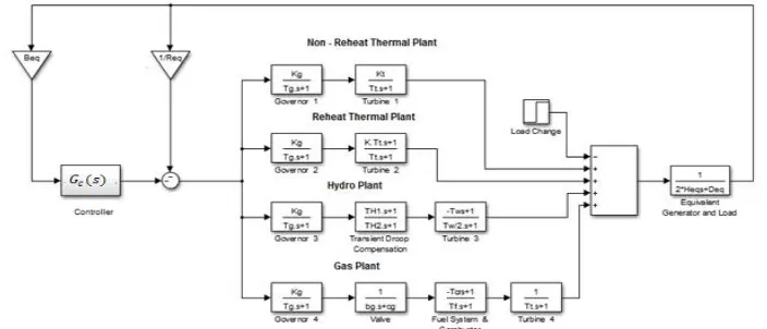
Practically several generating units operate in parallel in a single area. For analysis sake an equivalent generator will be used to represent n generating units in each area using the following equations (1) & (2).
= ; = (1)
= + 1 (2)
Accordingly AGC modelling of a single area power system with Non-Reheat Thermal, Reheat Thermal, Hydro and Gas plants is shown in Fig 1.
Fig 1. Multi source single area AGC block diagram
= ∆ + ∆ (3)
where Ki decides the quantity of interaction in the adjacent areas during a disturbance. For an overall satisfactory performance Ki may be chosen as , the frequency bias factor.
= ∆ + ∆ (4)
The block diagram of three area multi source power system is shown in Fig 2.
Fig 2. Block Diagram of Three Area multi source Power system
III.
A
CTIVED
ISTURBANCER
EJECTIONC
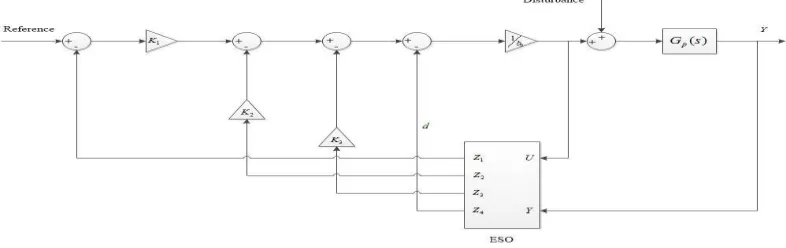
ONTROLTo improve the execution of the control law, the observation of the disturbance is vital. The active disturbance rejection control (ADRC), a technique for nonlinear uncertain system, is proposed by Han. It is error driven rather than model-based approach, which is similar to the most generally utilized PID controller. It employs an extended state observer (ESO) to evaluate and compensate the internal and external disturbances and a tracking differentiator (TD) to extract differentials of each order of the input signal. The TD not only traces the orientation of the input signal and arranges the expected transition process but also reduces the overshoot of system output. The nonlinear state error feedback control law determines the required control by calculating the difference between ESO and TD. The combination of these three powerful tools is best suitable for disturbance rejection control. All of the above lead to adequate stability margins and robustness, which have been confirmed by theoretical many practical applications. The basic structure of single area power system with primary loop is shown in Fig 3.
3.1 DESIGN OF ADRC FOR AN nth ORDER SYSTEM
Design of ADRC for an nth order system mainly involves three steps. They are 1. Plant Remodelling
2. Observer Gains Computation 3. Controller Gains Computation
General transfer function of the physical model considering primary loop is given by
( ) = ( )
( )=
+ +⋯… … . + +
+ +⋯… … . + + , ≥ (5)
where U(s) is the input of the plant and Y(s) is output of the plant. ai and bj are coefficients of transfer function. By long hand division, the plant is remodeled as
( ) = ( ) + ( ) (6) where = (7)
D(s) consists of both internal and external disturbances, bo is the high frequency gain and the plant is of order n-m. The disturbance will be estimated by an ESO and its impact will be removed by the process of disturbance rejection. The process of calculating the Observer Gains and Controller Gains are clearly discussed in Reference [13] and are given by Observer Gains with bandwidth
= − + 1 , = 1,2, … , − + 1. (8)
Controller Gains with bandwidth
= − −− + 1 , = 1,2, … − . (9)
By plant remodeling, finding the observer and controller gains, the basic topology of the ADRC is shown in fig (4)
Fig 4. Basic Topology of ADRC
3.1.1 DESIGN OF ADRC FOR AREA-1
The Design of ADRC mainly involves finding out the complete transfer function of the considered system, by which high frequency gain, observer gains, controller gains can be calculated. ADRC of Area-1 is designed based on the data taken from APPENDIX. Transfer functions of individual prime components in Area-1 are given as
For Non-reheat thermal plant: ( ) =( . )( .
)
For Reheat thermal plant: ( ) =
Since Hydraulic plant consists of non-minimum phase turbine and Gas plant consists of non-minimum phase combustor, while designing ADRC, an appropriate all pass filter to be cascaded with the corresponding systems to cancel out the positive zero and provide the necessary phase lead.
For Hydraulic plant: ( ) =( . )( .
)
For Gas plant: ( ) =( )( .( . )( .)( . )( .) )
Since the generating units of Area 1 are operating in parallel, overall transfer function of all prime components in Area-1 is given as
( ) = ( ) + ( ) + ( ) + ( )
( ) = 0.0055 + 0.02411 + 0.3388 + 2.0539 + 5.9322 + 7.949 + 4 0.000047 + 0.0021 + 0.0343 + 0.2657 + 1.0838 + 2.3432 + 2.493 + 1
Transfer function of equivalent generator plus load
( ) = 1 2 + =
1
2( 5 + 5 + 3 + 3 ) + 1.25 + 1.25 + 1 + 1= 1 32 + 4.5
Total forward transfer function of Area 1 is
( ) = ( ) ( )
( ) = 0.0055 + 0.02411 + 0.3388 + 2.0539 + 5.9322 + 7.949 + 4
0.0015 + 0.0674 + 1.107 + 8.6567 + 35.8772 + 79.8595 + 90.3204 + 43.2185 + 4.5
Hence complete transfer function of primary loop of Area-1 is
( ) = ( ) 1 + ( ) ( )
( ) = 1 = 1 +1 +1 +1 = 1 0.05+ 1 0.05+ 1 0.05+ 1 0.05= 80
( ) = 0.0055 + 0.02411 + 0.3388 + 2.0539 + 5.9322 + 7.949 + 4
0.0015 + 0.0674 + 1.547 + 10.5855 + 62.9812 + 244.1715 + 564.8964 + 679.1385 + 324.5
Thus for the transfer function of primary loop of Area-1, = 8, = 6
= + 1 = 4.5 + 80 = 84.5
High Frequency Gain: = .
. = 3.6423
Observer Gains:
Observer gains are obtained for the observer bandwidth of = 20 rad/s
= 8−6 + 1 1 20 =
3
1 20 = 60 ; = 3
2 20 = 1200 ; = 3
3 20 = 8000
Controller Gains:
Controller gains are obtained for the controller bandwidth of = 20 rad/s
= 8−6
8−6−1 + 1 20 = 2
2 400 = 400 ; = 2
1 20 = 20
3.1.2 DESIGN OF ADRC FOR AREA-2
The transfer function of primary loop of Area-2 is computed as
( ) = 0.0058 + 0.1779 + 1.574 + 5.5064 + 7.989 + 4
Here n=7, m=5, = .
. = 0.3625
Observer Gains: Observer gains are obtained for the observer bandwidth of = 20 rad/s.
= 60 = 1200 = 8000
Controller Gains: Controller gains are obtained for the controller bandwidth of = 20 rad/s
= 400 = 40
3.1.3 DESIGN OF ADRC FOR AREA-3
The transfer function of primary loop of Area-3 is computed as
( ) = 0.0007 + 0.0277 + 0.3737 + 2.2709 + 6.5354 + 8.5073 + 4
0.0015 + 0.0674 + 1.163 + 10.8727 + 65.7732 + 261.5315 + 613.1524 + 723.8025 + 324.5
Here n=8, m=6, = .
. = 0.4635
Observer Gains: Observer gains are obtained for the observer bandwidth of = 20 rad/s
= 60 = 1200 = 8000
Controller Gains: Controller gains are obtained for the controller bandwidth of = 20 rad/s
= 400 = 20
IV.
T
UNINGO
FPID
C
ONTROLLERA Proportional - Integrator - Derivative (PID) controller is a control loop feedback mechanism which constantly calculates an error value which is the difference between a required set point and a measured process variable. The basic structure of PID controller is given by
( ) = + + (10)
where , and are proportional, integral and derivative gain constants. One of the best possible methods for
tuning PID controller is Zeigler-Nichols method. It is a heuristic method which is performed by initially setting the integrator and derivative gain constants as zero. Then the proportional gain constant is tuned until the control loop output has stable and consistent oscillations. But in the case considered, consistent and stable oscillations are not
obtained. Therefore Zeigler-Nichols quarter amplitude decay method [16] can be used for such cases. In this method
also, initially Integral and Derivative gains are set to zero. Then the Proportional Gain (Kp) is tuned until it reaches the ultimate gain (Ku) at which the control loop output has the quarter amplitude decay for the oscillations obtained.
Fig 5. Quarter amplitude decay waveform
=1 4
Ultimate gain and the oscillation period Tu (=T2-T1) are used for setting the P, I and D parameters of the controller.
= 0.6 ; =1.2 ; =0.6
0.8 (11)
For the MSMA power system considered, = 0.6 and = 0.8
V.
S
IMULATIONA
NDR
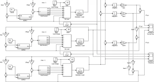
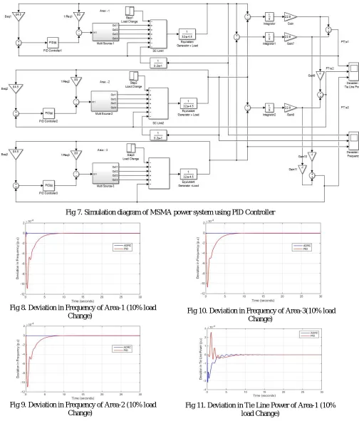
ESULTSThe structure of the Multi Source Multi Area Power System considered is shown in Fig 2. All the three areas are connected via AC links. A DC link is used which is connected in parallel with AC link between areas 1 and 2. The advantage of placing DC link in the power system is discussed in [13]. Simulation of AGC of MSMA power system with governor dead band using ADRC and PID Controllers (tuned by Quarter amplitude decay method) in MATLAB Simulink is shown in Figs 6 and 7 respectively. The comparison of resultant waveforms is shown in Figs 8 - 25.
Fig 7. Simulation diagram of MSMA power system using PID Controller
Fig 8. Deviation in Frequency of Area-1 (10% load Change)
Fig 9. Deviation in Frequency of Area-2 (10% load Change)
Fig 10. Deviation in Frequency of Area-3(10% load Change)
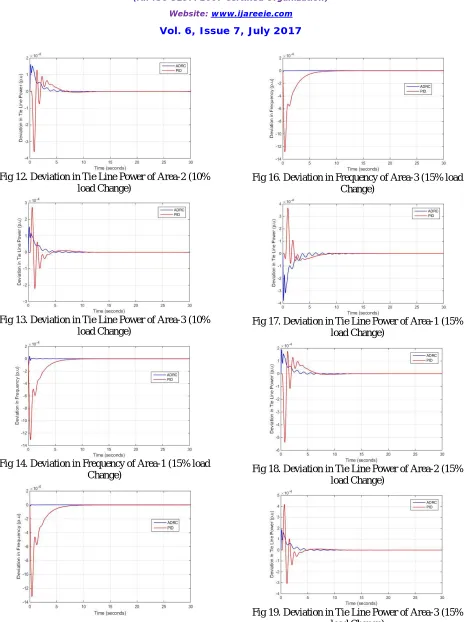
Fig 12. Deviation in Tie Line Power of Area-2 (10% load Change)
Fig 13. Deviation in Tie Line Power of Area-3 (10% load Change)
Fig 14. Deviation in Frequency of Area-1 (15% load Change)
Fig 15. Deviation in Frequency of Area-2 (15% load Change)
Fig 16. Deviation in Frequency of Area-3 (15% load Change)
Fig 17. Deviation in Tie Line Power of Area-1 (15% load Change)
Fig 18. Deviation in Tie Line Power of Area-2 (15% load Change)
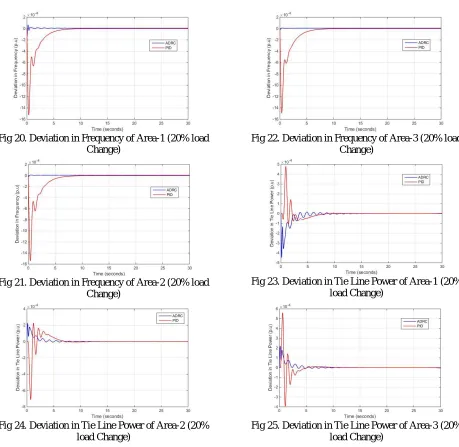
Fig 20. Deviation in Frequency of Area-1 (20% load Change)
Fig 21. Deviation in Frequency of Area-2 (20% load Change)
Fig 22. Deviation in Frequency of Area-3 (20% load Change)
Fig 23. Deviation in Tie Line Power of Area-1 (20% load Change)
Fig 24. Deviation in Tie Line Power of Area-2 (20% load Change)
Fig 25. Deviation in Tie Line Power of Area-3 (20% load Change)
VI.
D
ISCUSSIONTable 1 Settling Time, s for MSMA Power System
ADRC PID
∆PTie1 3.8 7
∆PTie2 3.8 6.5
∆PTie3 4.5 5
∆F1 0.2 6.5 ∆F2 0.1 6.5 ∆F3 0.1 6.5
VII.
C
ONCLUSIONSHere a MSMA three area power system with governor dead band is considered. Each area consists of reheat and non-reheat Thermal, Hydro and Gas plants connected in parallel. All these generators together are represented by a single equivalent generator. Appropriate all pass filters are used for Hydro and gas plants to convert their non-minimum phase transfer functions to minimum phase. ADRC and PID controllers are proposed here to enhance performance of AGC. The modelling of this system is carried out in per unit power and per unit frequency.The simulation results of this system with different loading conditions (10, 15, and 20% change) are given in Figs 8 - 25 and Table 1. From these results it is obvious ADRC is a better controller for this MSMA power system and is a robust controller as it can handle higher load changes efficiently with low overshoots and settling times. MSMA AGC of more areas may be considered for further research. Also renewable energy sources like Solar and Wind generators may be considered in each area along with the conventional generators for AGC study of MSMA power systems as further research.
ACKNOWLEDGMENT
We greatly acknowledge Siddhartha Academy of General and Technical Education, Vijayawada for providing the facilities to carry out this research.
REFERENCES
[1] A Textbook on Modern Power System Analysis by Hadi Sadat, Tata McGraw-Hill Edition 2002.
[2] A Textbook on Power Generation, Operation and Control by Allen J. Wood and Bruce F. Wollenberg, Second Edition, Wiley Student Edition. [3] A Textbook on Power Systems Analysis by Arthur R. Bergen and Vijay Vittal, Second Edition, Pearson Education, 2006.
[4] Omveer Singh and Ibraheem Nasiruddin, “Optimal AGC regulator for multi-area interconnected power systems with parallel AC/DC links”, Cogent Engineering (2016), 3: 1209272.
[5] Zhiqiang Gao, Yao Zhang, Lili Dong, “Load Frequency Control for Multiple-Area Power Systems”, American Control Conference Hyatt Regency Riverfront, St. Louis, MO, USA, June 10-12, 2009.
[6] Hassan A. Yousef, Khalfan AL-Kharusi, Mohammed H. Albadi and Nasser Hosseinzadeh, “Load Frequency Control of a Multi-Area Power System: An Adaptive Fuzzy Logic Approach”, IEEE transactions on power systems, Vol. 29, no. 4, July 2014.
[7] K. Hari Krishna, Dr. K.Chandrasekhar, “AGC in Multi Area Multi Source Deregulated Power Systems with AC & DC Tie”, International Journal of Advanced Research in Electrical, Electronics and Instrumentation Engineering(IJAREEIE), Vol. 4, Issue 5, May 2015
[8] K. Saiteja and M.S. Krishnarayalu, “Load Frequency Control of Two-Area Smart Grid”, International Journal of Computer Applications (0975 – 8887) Volume 117 – No.14, May 2015.
[9] K. Nagarjuna and Dr. M.S. Krishnarayalu, “ADRC for Two Area-LFC”, International Journal of Engineering Research & Technology (IJERT) Vol. 3 Issue 11, November-2014.
[10] K. Nagarjuna and M.S. Krishnarayalu, “AVR with ADRC”, International Electrical Engineering Journal (IEEJ) Vol. 5 (2014) No.8, pp. 1513-1518.
[11] Li Yujiao, Dong Lei, You Yuyang, Gao Yang and Liao Xiaozhong, “Load Frequency Control Based on ADRC for Interconnected Power System”, Proceedings of the 33rd Chinese Control Conference July 28-30, 2014, Nanjing, China
[12] Z. Gao. “Active disturbance rejection control: a paradigm shift in feedback control system design”, Proceedings of the American Control Conference, 2006: 2399-2405.
[15] V.Jyothi, P. Bharat Kumar, “Tuning controller parameters and load frequency control of multi-area multi-source power system by PSO Technique”, International Research Journal of Engineering and Technology (IRJET), Volume: 02 Issue: 08 | Nov-2015.
[16] J. G. Ziegler and N. B. Nichols: Optimum Settings for Automatic Controllers, Trans. ASME, Vol. 64, 1942, s. 759-768
[17] C.Karthik and Mr.P.Vijayarajan, “Design of fuzzy logic controller based load frequency control for multi source multi area system”, International Conference on Explorations and Innovations in Engineering & Technology (ICEIET - 2016).
[18] K.Jagatheesan, B. Anand and Nilanjan Dey , “ Conventional controller based AGC of Multi area Hydro-Thermal power systems” 2016 International Conference on Computer Communication and Informatics (ICCCI-2016) Jan 07-09, Coimbatore, India
[19] Yogendra Arya, Naredra Kumar, Hitesh Dutt Mathur, “Automatic Generation Control in Multi Area Interconnected Power System by using HVDC Links”, International Journal on Power Electronics and Drive Systems (IJPEDS), Vol 2, No. 1, March 2012, pp 67-75, ISSN:2088-8694.
[20] IEEE Committee Report (1970) IEEE Standard Definitions of Terms for Automatic Generation Control of Electric Power System. IEEE Transactions on Power Apparatus and Systems, PAS-89, 1358-1364.
APPENDIX
Sources Areas
Non Reheat Thermal Plant
Reheat Thermal Plant Hydro Plant Gas Plant
Area – 1
Kg =1; Tg = 0.1s; KT =1; TT = 0.4s;
H =5s; D = 1.25 pu; R = 0.05 pu
Kg =1; Tg = 0.2s; KT = 0.5; TT =0.4s;
H =5s; D = 1.25 pu; R = 0.05 pu
Kg =1; Tg =0.2s; TH1 =0.5s; Tw = 1s;
TH2 =0.513s; H = 3s;
D = 1 pu, R = 0.05 pu
XG = 0.6; YG = 1;
cg=1;bg=0.05;TT=0.2s;
Tcr=0.01s; Tf = 0.23s;
KT =1;H =3s;D=1 pu;
R = 0.05 pu
Area – 2
Kg =1;Tg =0.2s; KT =1; TT =0.4s;
H =5s; D = 1.25 pu; R = 0.05 pu
Kg =1; Tg = 0.2s; KT = 0.5; TT =0.4s;
H =5s; D = 1.25 pu; R = 0.05 pu
Kg =1; Tg =0.2s; TH1 =0.5s; Tw = 1s;
TH2 =0.513s; H = 3s;
D = 1 pu, R = 0.05 pu
XG = 0.6; YG = 1;
cg=1;bg=0.05;TT=0.2s;
Tcr=0.01s; Tf = 0.23s;
KT =1;H =3s;D=1 pu;
R = 0.05 pu
Area – 3
Kg =1;Tg =0.2s; KT =1; TT =0.4s;
H =5s; D = 1.25 pu; R = 0.05 pu
Kg =1; Tg = 0.1s; KT = 0.5; TT =0.4s;
H =5s; D = 1.25 pu; R = 0.05 pu
Kg =1; Tg =0.2s; TH1 =0.5s; Tw = 1s;
TH2 =0.513s; H = 3s;
D = 1 pu, R = 0.05 pu
XG = 0.6; YG = 1;
cg=1;bg=0.05;TT=0.2s;
Tcr=0.01s; Tf = 0.23s; KT =1;