Steam Boiler Drum Level Control using DCS -
One/Three Element Method
Lakshmi P M1, Dr.H.Prasanna Kumar2
PG Scholar, Department of Electrical Engineering, University Visvesvaraya college of Engineering(UVCE), Bengaluru, India1
Assistant Professor, Department of Electrical Engineering, University Visvesvaraya college of Engineering(UVCE), Bengaluru, India2
ABSTRACT: The scope of this control system is to maintain the boiler drum level to the normal water level at all loads. Boiler drum level control is critical for both thermal plant protection and equipment safety and applies equally to both high and low levels of water within the boiler drum. Proper boiler operation requires that the level of water in the steam drum can be maintained within a certain band. A dramatic decrease in this may uncover boiler tubes, allowing them become overheated and damagedand if the water level in the drum rises above the desired upper drum level, there will be a carryover of water particles in the dry steam flowing to the turbine and thus the turbine blade damage the turbine blades. Single/Three element feed water control system is provided to regulate the quantity of feed water flowing into the boiler to maintain the required water level in the steam drum.
I. INTRODUCTION
The boiler drum level control with DCS in thermal power station, with some modification is taken as a project work. Steam generation in the boiler is proportional to the power generation by supplying a required steam flow to the turbine. As the steam flow is proportional to the Power generation, always there will be fluctuations in the drum level. If the drum level goes below the desired lower drum level, there will be every possibility of starvation of water tubes inside the furnace and the boiler may get damaged. If the water level in the drum rises above the desired upper drum level, there will be a carryover of water particles in the dry steam flowing to the turbine and thus the turbine blade damage is expected.In the paper Importance of three-elements boiler drum level control and its installation in power plant [5] Sanjoy Kumar Chakraborty, Nilotpal Manna and SurodhDey explained that the Conversion of water into steam is the primary function of a utility boiler.
For safe and efficient boiler operation, a constant level of water in the boiler drum is required to be maintained. Therefore it is extremely important to have the knowledge of the operating principles, installation requirements, strength and weaknesses of drum water level control system. Ignoring these considerations can result in misapplication, frequent maintenance, unsafe operation and poor instrument as well as system performance. In this paper design aspects and installation requirements of boiler drum level control are discussed for safe and economic operation.
It has already been reported by KeyurSolanki, Jalpa Shah and Nishith Bhatt in the paper Modeling and simulation of prototype of boiler drum level control [1] proposed an approach for controlling a very crucial parameter of boiler i.e. level of the boiler drum using PID controller. IMC based PID tuning method is used with feed forward and feedback strategy is used to control two element drum level.
K. Ghousiya Begum, D.Mercy, H. KirenVedi and M. Ramathilagam reported that there are three different types of drum level control methods such as Single element boiler drum level control, two element boiler drum level control and three element boiler drum level control. The parameters of boiler drum level control system are determined using PID control tuning methods such as Ziegler-Nichols method, Tyreus-Luyben method and Internal Model Control (IMC), in which IMC surpasses the performance of the conventional controller, in the paper An Intelligent Model Based Level Control of Boiler Drum[2].
ISSN (Print) : 2320 – 3765 ISSN (Online): 2278 – 8875
I
nternational
J
ournal of
A
dvanced
R
esearch in
E
lectrical,
E
lectronics and
I
nstrumentation
E
ngineering
(An ISO 3297: 2007 Certified Organization)
Vol. 5, Issue 8, August 2016
transfer, which is Wide Fast Combination of batch and continuous type operations such that plant steam load characteristics varies continuously and usually unpredictably. Here they used the wide opening technology for conservation of the energy in the paper Boiler drum level control by using wide open control with three element control system [3].
It has already been reported in the paper Linear Analysis and Control of a Boiler-Turbine Unit [4] by Wen Tan and Fang Fang Boiler-turbine units are multivariable nonlinear systems. The control of such systems is not easy considering the practical tuning, implementing and maintaining problems. In this paper, the design of a linear controller for the Dalate No.4 unit is reported.
H. Moradia A. Alastya, M. Sa_ar-Avvalb and F. Bakhtiari-Nejad [6] reported in a paper, a nonlinear Multi Input-Multi Output model (MIMO) of a utility boiler turbine unit is considered. Drum pressure, generator electric output and drum water level (as the output variables) are controlled by manipulation of valves position for fuel, feed water and steam flows.
The paper is outlined as follows: Section-II of the paper discusses the methodology applied on drum water level controller. Section- III describes the different level of controlling the drum water level. Section-IV demonstrates the Analysis of the methods applied for a drum water level control and finally the conclusions are given in section-V.
II. METHODOLOGY
Conversion of water into steam is the primary function of a utility boiler. The steam pressure is used to turn a steam turbine thus, generating electricity. Within the boiler drum there exists a steam/water interface. Boiler steam drum water level is one of the important parameters of power plant that must be measured and controlled. For safe and efficient boiler operation, a constant level of water in the boiler drum is required to be maintained.
The two main control systems that are available in a power plant are as follows:
Open loop controls (OLCS).
Closed loop controls (CLCS).Open loop controls (OLCS).
Single Element Drum Level Control Loop(LIC-701A):
During lower boiler loads (<30% steam flow), drum level signal and the fixed local setpoint is compared in LIC-701A and the controller output is fed to feed water 30% control valve FCV-602.When the drum level is below the setpoint, controller LIC-701A will further increase the level by opening the feed water control valve FCV-602. When the drum level is above the setpoint the reverse action will be taken.
The level is measured by three independent transmitters LT-701A, LT-701B & LT-701C. All the three level signals are corrected for density using the drum pressure signal. The density compensation is given using below equation. After density compensation same is used for indication, control & high, low alarm generation. Further middle value is also performed on the three density compensated level signal and the output of LY-701 is used as PV (process variable) for the drum level controller LIC-701A & LIC-701B.
For drum level very high trip contacts are generated from individual density compensation blocks and then 2oo3 voting is performed on these digital signals.
The Steam drum pressure is measured using pressure transmitter PT-701 & PT-702. The output of PT-701 & 702 will be connected to PY-701 block for 1oo2 or average value selection. When the selected pressure transmitter is failing, PY-701 must change the selection to other transmitter automatically. During changeover the output of PY-701 shall be kept at the last good value prior to transmitter failure. An alarm must be given to the operator for transmitter failure.
Figure 1. Water level measurement in a pressure vessel
HmCompensated drum level. DwDensity of water in gm/cm3
Da Density of water at ambient temperature (34°C) =0.994 gm/cm3.(water in Condensate pot) Ds Density of Steam in gm/cm3
H Distance between tapping points/ Water head on LP side = 800 mm
Head acting on HP side = Hm × Dw + (H−Hm) × Ds. Head acting on LP side = H × Da
Delta P = HP-LP.
= Hm × Dw + (H−Hm) × Ds– H × Da
Hm = ( () ( ) )
Compensated level (Hm) derived from above equation shall be in scale 0 -800 mm. This value shall be scaled to 0 -100 % range for display and alarm in DCS.Delta P is the differential pressure value from drum level transmitters LT-701, LT-702 & LT-703 is (-) 800 to 0mmwc.
Above equation to be implemented in level compensation block LX-701, LX-702 & LX-703.The values of Dw and Ds will be taken from following look-up table depending upon the current drum pressure signal from PY-701.
Three Element Drum Level Control Loop(LIC-701B): Table 1
The aim of this control loop is to maintain the drum level at the normal water level by using a three element level control function. The three elements in this control loop are the drum water level, the steam flow and the incoming feed water flow.
Drum Pressure
Dw Density of water in
ISSN (Print) : 2320 – 3765 ISSN (Online): 2278 – 8875
I
nternational
J
ournal of
A
dvanced
R
esearch in
E
lectrical,
E
lectronics and
I
nstrumentation
E
ngineering
(An ISO 3297: 2007 Certified Organization)
Vol. 5, Issue 8, August 2016
This feedwater flow demand is compared against measured feedwater flow. The feedwater flow controller uses any resulting error to adjust the position of the feedwater flow control valves.
The steam flow is measured by three independent transmitters FT-701, FT-702 & FT-703. Further middle value is also performed on the three transmitters. The steam flow transmitters are connected across flow nozzle and the signal is then pressure and temperature compensated. The compensation block FX-701 takes care of any error, which may arise due to density variation of steam if boiler is operating at conditions different from design parameters. The density compensation is given using below equation. After density compensation same is used for indication, control & high, low alarm generation. The output of the FX-701 acts as a feed forward signal & takes care of the shrink & swell effect.
LIC-701B is the primary controller in the three element level control function. When the steam drum water level is below the set point, controller LIC-701B will further increase the remote set point of the feed water flow controller to increase the feed water flow. When the level is too high the reverse action will take place.In case the Level is High or Low, the operator is alarmed to check for the possible reasons.
Steam Temperature & Pressure Compensation(FX-701): Actual Steam Flow = Qmean×
( . )( )
( . )( )
Qmean - Median Value Measured Steam Flow FT-701,702&703
P2 - Average Value Measured Pressure Signal. PT-704 & 705 T2 - Average Value Measured Temperature Signal. TT-708 &709 P1 - Design Pressure (Constant) 112 Kg/cm2 T1 - Design Temperature(Constant) 542°C .
Flow indicator FI-701 and flow totaliser FQ-701 are provided. Steam flow signal FI-701 is used in combustion control scheme to derive the oxygen level, bed temperature & upper shaft diff. pressure etc. at various loads.
Summing Block(FY-602): The Level controller output signal is added with the compensated steam flow signal at summing block. The following equation is implemented in summing block
Remote SP for (FIC-601) % = (LIC-701B) O/P + Steam Flow (FX-701) PV in % - 50%
All the inputs are converted to % before processing, suitable engineering scaling is done for all indications. All compensation and function blocks have limits to avoid arithmetic overflow.The computed signal from summing block acts as remote setpoint for feed water flow controller FIC- 601.
Feed Water Flow Control Loop (FIC-601): The aim of this control loop is to maintain the drum level at the normal water level by regulating the 100% feed water flow control valves FCV-601 or MOV-611. FIC-601 is the secondary controller in the three element level control. When the feed water flow is below the setpoint, controller FIC-601 will further increase the feed water flow by opening the feed water control valve. When the flow is too high the reverse action will takeplace.
Feed Water Density Compensation (FX-601): Actual Feed water Flow =
Measured water density in kg/m3 =1000 1− .
. × . ( −3.9863)
When main steam flow FI-701 PV is less than 95 TPH then switch SS-701 selector position to select the single element LIC output. When single element selected, main steam flow is greater than 95 TPH & less than 105 TPH then selector will select the single element LICoutput.
When main steam flow FI-701 PV is greater than 105 TPH then switch SS-701 selector position to select the three element FICoutput.
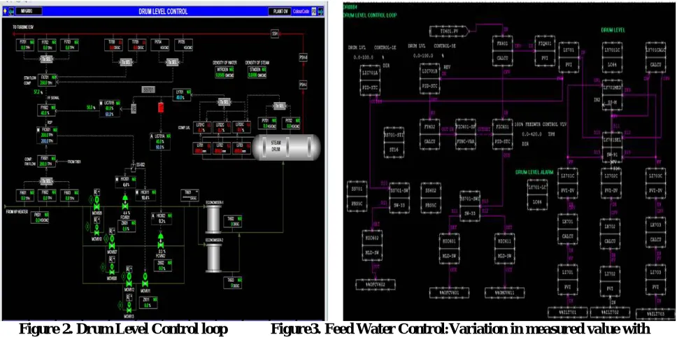
Figure 2. Drum Level Control loop Figure3. Feed Water Control:Variation in measured value with
process Value
ISSN (Print) : 2320 – 3765 ISSN (Online): 2278 – 8875
I
nternational
J
ournal of
A
dvanced
R
esearch in
E
lectrical,
E
lectronics and
I
nstrumentation
E
ngineering
(An ISO 3297: 2007 Certified Organization)
Vol. 5, Issue 8, August 2016
III. RESULT AND DISCUSSIONS
The below figure shows the main steam pressure compensation. It is used for drum level measurement and controlling.
Figure 4.Graph of MV with PV (SV constt.)
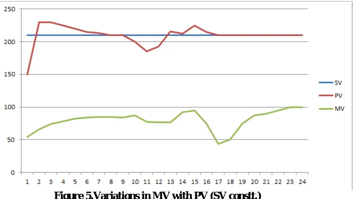
This graph depicts the variation in Drum level during the operation. The variation in drum level is caused by the variations in steam generation. Here SV is the set value i.e. the desired value of drum level in mm. PV is the process value which is the actual drum level in mm at a given instant in the actual process. MV is the Measure value which represents the difference in the PV and SV. It is measured in percentage terms and given to the inlet value for the open and close action to control the inlet flow.
Figure 5.Variations in MV with PV (SV constt.)
IV. CONCLUSION
The boiler drum level is greatly improved by the level compensation method, this DCS based control system for drum level control has successfully replaced the human operator to gain automatic performanceAs this method uses level compensation using temperature, pressure and density of water and steam the boiler drum, it eliminates the error would cause by the water bubbles.
The DCS provides a simplified process mode of helping the user with less interference. The output is seen on the HMI(Human Machine Interface) helps the user interact better with system
REFERENCES
[1]. Modeling and Simulation of prototype of boiler drum level control, KeyurSolanki, Jalpa Shah and Nishith Bhatt, ISSN (Print) : 2321-5747, Volume-2, Issue-2,20 International Journal on Mechanical Engineering and Robotics (IJMER).
[2]. International Journal of Emerging Technology and Advanced Engineering Website: www.ijetae.com (ISSN 2250-2459, ISO 9001:2008 Certified Journal, Volume 3, Issue 1, January 2013), An Intelligent Model Based Level Control of Boiler Drum, K. Ghousiya Begum, D.Mercy, H. KirenVedi, M. Ramathilagam.
[3]. International Monthly Refereed Journal of Research In Management & Technology , Volume II, April’13 ISSN – 2320-0073 ,
www.abhinavjournal.com, boiler drum level control by using wide open control with three element control system , T. Rajkumar1, V. M. RamaaPriyaa and K.Gobi. Proceedings of the 17th World Congress
[4]. The International Federation of Automatic Control, Seoul, Korea, July 6-11, 2008, Linear Analysis and Control of aBoiler-Turbine Unit, Wen Tan and Fang Fang.
[5]. International Journal of Instrumentation and Control Systems (IJICS) Vol.4, No.2, April 2014 DOI : 10.5121/ijics.2014.4201 1, importance of three-elements boiler drum level control and its installation in power plant, Sanjoy Kumar Chakraborty, Nilotpal Manna and SurodhDey. [6]. Multivariable control of an industrial boiler-turbine unit with nonlinear model: A comparison between gain scheduling and feedback
linearization approaches, H. Moradia, A. Alastya, M. Saar-Avvalb and F. Bakhtiari-Nejad, ScientiaIranica B (2013) 20(5),
[7]. TANAKA Mihoko, SURENDRA C. RAMARAO. ,“CENTUM VP Graphic System –Towards Integrated HMI–”,Yokogawa Technical Report, No. 45, 2008, pp. 43-46