Beam-Forming and Beam-Steering Capabilities of a Reconfigurable
Plasma Antenna Array
Anuar D. J. Fernandez-Olvera1, Davide Melazzi2, and Vito Lancellotti1, *
Abstract—We present the numerical parametric study of a reconfigurable plasma antenna array (PAA) composed of a metallic half-wavelength dipole and a set of cylindrical plasma discharges arranged in a planar square lattice. Our results, obtained with the linear embedding via Green’s operators (LEGO) method, indicate that beam-forming and beam-steering functionality can be achieved and controlled by appropriately choosing the number and position of the active plasma discharges around the dipole. Furthermore, we show that an external static magnetic field and the plasma density have a noticeable effect on the radiation pattern of the antenna.
1. INTRODUCTION
Traditionally, antennas have been defined as metallic or dielectric structures able to generate or receive electromagnetic (EM) waves [1, 2], and antenna design has focused on choosing the appropriate geometry, size, array configurations, and materials to achieve, for instance, a desired radiation pattern (RP). Recently, there has been a growing interest in the use of plasma discharges [3–7] as passive or active antenna elements because the latter have potential advantages over conventional metallic antennas. Most notably, plasma discharges can be employed to build reconfigurable structures with low radar cross section. In particular, a Gaseous Plasma Antenna (GPA) consists of a plasma discharge confined in a dielectric tube which may come in different shapes, e.g., loops or rods. On the other hand, depending on the intended application, the plasma can be generated by feeding EM power through various methods, e.g., direct-current (DC) discharge or Radio Frequency (RF) surface-waves [8, 9].
A GPA can transmit and receive EM waves similarly to a metallic antenna [10], when the plasma tube is energized and the antenna is driven at a frequency smaller than the plasma frequency [11]. In fact, it has been shown that the performance of a GPA is equivalent to that of a metallic counterpart in every respect [12]. However, GPAs have received attention and stimulated research for some distinctive characteristics of theirs such as being transparent to incoming EM waves whose frequency is greater than the plasma frequency [5] as well as the possibility to be reconfigured electrically — rather than mechanically — with respect to frequency, gain and beam-width. Reconfiguration capabilities stem from the accurate control of the plasma density and, if present, an applied magneto-static fieldB0 [13–
15]. What’s more, GPAs designed to operate in a given range of frequencies are virtually unaffected by GPAs which are intended to work at lower frequencies; as a result, GPAs of different types can be stacked to form arrays while reducing or eliminating co-site interference.
A Plasma Antenna Array (PAA) is an aggregate of GPAs and possibly conventional metallic elements [16–18]. In addition to the advantages of baseline GPAs, PAAs can afford multi-beam operation, beam-steering, and better directivity. Also, an array of plasma discharges surrounding a radiating element — which can be either metallic or a GPA — effectively realizes a “plasma blanket”
Received 15 March 2016, Accepted 6 June 2016, Scheduled 10 June 2016
* Corresponding author: Vito Lancellotti ([email protected]).
1 Faculty of Electrical Engineering, Eindhoven University of Technology, Eindhoven, The Netherlands. 2Department of Industrial
of sorts that can be used to shield unwanted incoming EM waves or to open “windows” in suitable positions so as to let outward EM waves through [19, 20]. In such configurations, the control of the RP and the beam is based upon the state (on or off) of the discharges and the plasma properties thereof as well as the interaction between the plasma window and the incident EM wave.
In conventional antenna arrays the direction and the width of the main lobe is determined, to a large extent, by the relative positions of the elements and the RP thereof [2]. Still, the overall RP of the array can be controlled by adjusting amplitude and progressive phase difference of the excitation of the elements [1]. Moreover, with the so-called scanning arrays, the main beam can in principle be squinted continuously and dynamically, provided the phase shifting is realized electronically [21, 22]. Finally, in modern high-capacity wireless communication infrastructures, the antenna arrays employed in cellular base stations must be able to adaptively change the direction of maximum gain while selectively placing nulls in the RP [1]. This feature, known as beam-forming, is realized by means of feeding networks endowed with signal-processing algorithms that compute the excitation coefficients of the array elements on the fly [1], and this approach remains the best option for realizing elaborate reconfigurable RPs.
Nevertheless, it has also been shown that PAAs can provide simple forming and beam-steering capabilities [17, 18, 20], and in this paper we report on the numerical analysis of a PAA that combines an intrinsically non-directive antenna — a dipole — with a set of plasma discharges [16]. We refer to the resulting device as a reconfigurable PAA because the RP — chiefly the direction and the width and the intensity of the main lobe — can be modified by selectively switching on and off the plasma discharges as well as by controlling the plasma properties. More specifically, the PAA under investigation is composed of a standard metallic half-wavelength dipole antenna surrounded byND = 32 identical finite-size plasma discharges which are generated and confined in cylindrical glass canisters. The plasma discharges are arranged in a 6×6 square lattice with the dipole placed at the center of the square. In the light of the square symmetry, we expect that the PAA can direct the main lobe in four angular sectors of 90◦, each corresponding with one side of the square; this means the PAA performs as a sectoral array [1]. Furthermore, we show that, within a given angular sector, the maximum gain can be adjusted by varying the position and the number of the active plasma discharges. However, also the plasma parameters, such as the density, have a noticeable effect on the RP [13, 23]. For instance, an external static or quasi-static magnetizing field B0 — which makes the plasma anisotropic
and non-reciprocal — can be used to additionally fine-tune the squint of the beam. Finally, since the PAA comes naturally decomposed into well-separated parts (the discharges and the dipole), to solve this EM problem numerically we have employed the linear embedding via Green’s operators (LEGO) method [24, 25] combined with the electric field integral equation (EFIE) [26], as the latter approach can efficiently handle the wave scattering from an aggregate of objects with limited translational symmetry. Although accounts of experimental and theoretical work on GPAs and PAAs can be found in literature, the specific configuration of dipole antenna and plasma discharges addressed in this paper is different for many a reason. In [3], for instance, a single plasma tube was used as a radiating element in the frequency range between 3 and 50 MHz, whereas the antenna of concern here relies on an array of discharges to realize a plasma blanket around a conventional dipole which is the true source of EM waves in the microwave regime. In [4], the Author proposed an agile plasma mirror (i.e., a planar plasma layer) for steering the beam of a directive antenna; in fact, much emphasis was laid on the theoretical and practical aspects of the plasma generation. Conversely, in this work, we concern ourselves with the beam-steering performance of the PAA while assuming the plasma blanket consists of preformed plasma discharges.
An extensive report on various configurations of GPAs and PAAs was presented in [5], where the Authors discussed, among others, a cylindrical arrangement of fluorescent lamps around a 1.7-GHz transmitter and in front of an 8-GHz transmitting horn antenna. The focus was on demonstrating the ability of the plasma blanket to block incoming EM waves at the lower frequency and to let through signals at the higher frequency. In this paper, we take advantage of the shielding properties of plasma and, through numerical analysis, show that the PAA can direct the EM waves produced by the dipole towards desired controllable directions.
— and for the geometry — fully 3-D versus planar.
A circular arrangement of non-magnetized plasma discharges was theoretically investigated in [17]; the Authors assumed infinitely-long circular tubes and an elementary line current as the primary source of EM waves. By contrast, in this paper we consider a practical source of EM waves — a dipole — and magnetized discharges the length of which is comparable to that of the dipole, whereby the assumption of infinitely-long tubes cannot be invoked. In this regard, our analysis indicates that the finite length of the tubes does have an effect on the RP of the PAA. Moreover, in [17] the Authors obviate the influence that the plasma discharges may have on other antenna parameters such as the impedance. This is a topic we investigate, since the impedance is fundamental in the design process.
Lastly, circular and square arrangements of discharges were experimentally investigated in [19] and [20], respectively. In either paper, the Authors considered a single tier of off-the-shelf fluorescent lamps surrounding a quarter-wavelength monopole on a ground plane. In this work, on the other hand, the dipole is fenced by two tiers of plasma tubes, and the effect of the plasma parameters is explored by means of a suitable dispersion model for the permittivity.
The rest of the paper is organized as follows. In Sections 2.1 and 2.2 we outline the mixed LEGO-EFIE approach and describe the modelling of the PAA, whereas in Section 2.3 we introduce the macroscopic description of the plasma by means of a dyadic permittivity. In Section 2.4 we consider the numerical solution of the LEGO-EFIE functional equation with the Method of Moments (MoM) and the eigencurrents [24, 26, Section 5], and elaborate on the convergence of the desired observable quantities as a function of the number of eigencurrents. Finally, in Section 3.1 we analyze the beam-forming and beam-steering capabilities of the PAA by considering RP and gain function, whereas the effect of the plasma discharges on the antenna impedance and radiated power is addressed in Section 3.2. A time dependence in the form of exp(jωt) for fields and sources is assumed and suppressed throughout.
2. ANTENNA MODELLING AND NUMERICAL SOLUTION WITH LEGO-EFIE
2.1. Domain Decomposition with Mixed LEGO-EFIE
In the LEGO setup [24–26], we model an aggregate of ND identical anisotropic objects by defining as many simple-shaped EM “bricks” Dk, k= 1, . . . , ND, each one enclosing an object and characterized through a scattering operator Skk. We then account for the multiple scattering that occurs between
Dk and Dn, n = k, by means of the transfer operators Tkn and Tnk. With these ingredients, we can formally describe the EM response ofND bricks by means of the total scattering operatorS, viz.,
S:= (diagS−kk1−T)−1, (1)
where Tis the ND ×ND abstract matrix of transfer operators given explicitly in [27, Eq. (6)]. Lastly, we introduce the operators (PAO)k and (TOA)k to describe the multiple scattering between Dk and the metallic parts, when present. It can be shown that the radiation from a perfect electrically conducting (PEC) antenna in the presence of the LEGO bricks is governed by a modified EFIE [26], namely,
η1(LA+PAOSTOA)JA=−[EgA]tan, on SA, (2)
where SA is the total surface of the PEC elements, JA the equivalent electric surface current thereon,
and η1 = (μ1/ε1)1/2 denotes the intrinsic impedance of the background medium (➀). Aside from an
immaterial normalization factor,LA represents the standard EFIE operator on SA[26, Eq. (16)], while PAO, TOA are abstract 1×ND and ND ×1 vectors with operator entries (PAO)k, (TOA)k. Finally, [EgA]tan is the impressed field supplemented by the external generator in the delta-gap approximation of
the antenna port [26, Eq. (14)]. OnceJAand the equivalent surface currents over the bricks’ boundaries
have been computed, we can obtain the input impedance and the radiated fields.
The overall reliability of (1) and (2) and the correctness of the code implementing the LEGO approach along with the numerical solution (see Section 2.4) was tested in [24–26] by making crosschecks between results of the method employed and alternative methods of computation for the same quantities.
2.2. LEGO Model of the Plasma Antenna Array
0.020 0.02 0.02
0 0.02 0.06 0.04 0.02 0 0.02 0.04 0.06
x [m] y [m]
z [m]
0.010 0.01 0.010
0.01 0.05
0 0.05
x [m] y [m]
z [m]
0 0.1
0.2 0.3
0 0.1 0.2 0.3 0.05
0 0.05
x [m] y [m]
z [m]
0.03 0.02 0.01 0 0.01 0.02 0.03
z [m]
port
(a) (b) (c)
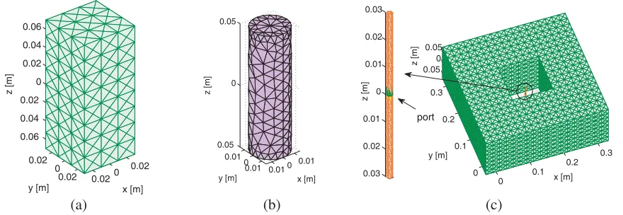
Figure 1. Reconfigurable PAA: (a) 3-D triangular tessellation of a cuboidal brick’s surface and (b) tetrahedral mesh of a cylindrical plasma discharge; (c) LEGO model showingND = 32 EM bricks in the case where all the plasma discharges are energized and (inset) a close-up of the 3-D triangular-faceted model of the PEC dipole antenna.
(Fig. 1(b)). In this way, various configurations of the PAA can be examined by simply changing the number of bricksND ≤32 in the model, as explained further on. The background medium (➀) in which the dipole and the plasma discharges exist, is free space (ε1 =ε0), and hence the host medium (➁) that
pads the inside of a brick is free space as well (ε2 =ε1). Moreover, since the permittivity of the glass
canisters which contain the plasma is approximately the same as that of free space and, in any case, is far smaller than the permittivity of the plasma (medium ➂), we can safely exclude the canisters from the numerical model. For the sake of simplicity, other metallic parts (e.g., excitation circuits of the plasma discharges) are not considered either, although the LEGO approach would allow doing so.
The cylindrical region occupied by a plasma discharge is 10 cm high and has a diameter of 3 cm. The discharges are arranged in a planar square lattice, so that the distance between the axes of two neighboring cylindrical discharges is 6 cm. This is also the length of the shorter edge of a brick, while the height thereof is 14 cm (see Fig. 1(a)). Finally, the half-wavelength dipole is 6 cm long, has a radius of 0.1 cm, and is placed at the center of the cluster of discharges, as illustrated in Fig. 1(c). The dipole is energized with VG= 1 V (see [26, Eq. (14)]) at the operational frequencyf = 2.27 GHz.
Shown in Fig. 1(c) is the LEGO model relevant to the special case where all theND = 32 plasma discharges are on. We refer to this setup — also shown in Fig. 2(a) without the enclosing bricks — as to “plasma on 2.” The other three configurations† examined in this work are: “plasma on 3” (Fig. 2(b)), “plasma window 2” (Fig. 2(c)) and “plasma window 5” (Fig. 2(d)). The configuration “plasma on 3” differs from “plasma on 2” for the absence of four plasma discharges at the four corners of the square lattice, and hence the active plasma discharges are ND = 28. In “plasma window 2” 10 plasma discharges are turned off on three sides of the square lattice; the remainingND = 22 active discharges provide a rear screen and a front opening through which the dipole is expected to radiate preferably. Finally, the same windowing concept is realized with the configuration “plasma window 5”, though ND = 24 active plasma discharges are retained.
The LEGO model of any configuration of the PAA looks similar to the one shown in Fig. 2(a) for “plasma on 2.” Yet, fewer LEGO bricks are generally involved, because only the bricks that enclose active plasma discharges must be included in the calculations on the grounds that a plasma discharge becomes “transparent” to EM waves when it is off. This assumption can be motivated by observing that, upon switching off the circuit that drives the discharge, the electrons and ions that form the plasma recombine to yield an electrically inert and neutral gas. Furthermore, the permittivity of the neutral gas is approximately the same as that of free space. From the viewpoint of the LEGO approach, the latter means that no object is present inside the relevant brick and, as medium ➀ and ➁ are also endowed with the same constitutive parameters, no scattered fields are produced in response to an
† The reason for the non-consecutive numbering of the configurations is that we have selected the most meaningful ones out of a
(a) (b)
(c) (d)
Figure 2. Reconfigurable PAA, LEGO models: (a) Configuration “plasma on 2” composed ofND = 32 energized plasma discharges; (b) Configuration “plasma on 3” comprised ofND = 28 energized plasma discharges; (c) Configuration “plasma window 2” composed of ND = 22 energized plasma discharges; (d) Configuration “plasma window 5” composed of ND = 24 energized plasma discharges. (Remark: inactive discharges, when present, are not shown.)
impinging EM wave. In conclusion, such an “empty” brick contributes naught to the EM model of the PAA, because the scattering operator degenerates into the null operator.
2.3. Model of the Plasma Discharges
The discharges considered in this work are composed of weakly ionized plasma in which the thermal motion of the particles can be ignored and the density is not disturbed by an impinging EM wave. As a result, the cold-plasma approximation and the fluid model are well justified for representing the plasma response [28], and the spatial distribution of the plasma density is temporally constant. Furthermore, we assume the plasma discharges have been preformed by some excitation circuits (e.g., in the microwave regime as in [12]) not included in the LEGO model for the sake of simplicity. More specifically, each tube is filled with the same uniform plasma made of argon ions, electrons and neutrals with an electron temperature of 3 eV and a neutral pressure of 15 mTorr. The plasma is collisional and possibly magnetized by an external magnetostatic field B0 parallel to the axis of the canisters.
Therefore, in a system of Cartesian coordinates in which B0 =B0ˆz, the permittivity dyadic reads: ε3(r;ω) :=S(ˆxˆx+ˆyˆy) +Pˆzˆz+ jD(xˆˆy−ˆyˆx), (3) with the coefficients (Stix parameters [11]) given by
S:= 1−
α
ω2pα(ω−jνα) ω[(ω−jνα)2−ω2
cα]
, P := 1−
α
ωpα2
ω(ω−jνα), D:=
α
σαωcαω2pα ω[(ω−jνα)2−ω2
cα]
, (4)
where the symbol α implies summation over the species that form the plasma. Besides, ωpα := [nαq2α/(ε0mα)]1/2 is the plasma frequency,ωcα:=σαqαB0/mα the gyrofrequency,σα:=±1 the particle
electron-electron and electron-neutral collisions are dominant and, in fact, dependent on the electron temperature and the operational frequency f. For instance, with the data listed above the electron collision frequency for a plasma densityne= 1018m-3is about 55 MHz atf = 2.27 GHz (see Sections 2.4
and 3). As a result, the plasma behaves as an opaque dielectric medium rather than as a conductor. As is well known, a cylindrical-shaped uniform plasma discharge can support surface plasmon waves propagating at the plasma-vacuum interface along the discharge axis. Since these waves are not excited at the chosen operational frequency (f = 2.27 GHz) for plasma densities in the range 1018–1020m-3(see Sections 2.4 and 3) the plasma tubes that form the PAA work in the regime of non-resonant scattering.
2.4. Solution with MoM and Convergence with Eigencurrents
To proceed with the solution of (2), we need to compute the algebraic scattering operators [Skk], k= 1, . . . , ND, [26, Eq. (44)] of the bricks. Still, since theND ≤32 discharges are identical, we must only determine [S11] and can even re-use it to analyze all the configurations of the PAA, as long as
neither the frequency nor the plasma parameters are varied. For the numerical inversion of (2) with the MoM [26, Section IV] we model the surface of the dipole (SA) and the surface of the bricks (∂Dk) with
3-D surface triangular tessellations, and the volume occupied by the plasma discharges with tetrahedral meshes. In particular, we employ NA = 372 (2NF = 1368) surface basis functions on SA (∂Dk), and
NO = 2544 volume basis functions in each plasma discharge. With these positions, the algebraic total scattering operators [S] [26, Eq. (49)] relevant to the four configurations of Figs. 2(a)–2(d) have rank 2NDNF ∈ {43776, 38304, 30096,32832}, respectively.
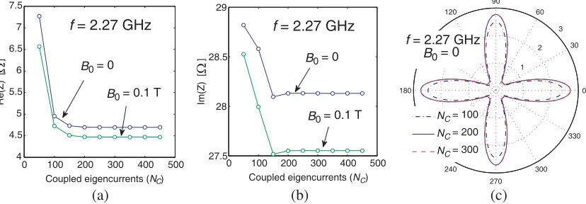
As explained in [26], we use the eigencurrents expansion method (EEM) in order to compute the contribution of the LEGO bricks to the modified EFIE (2). To this purpose, we must choose the number of coupled eigencurrents NC properly, because NC affects the calculation of [S]. Ideally, we would like to retain as few eigencurrents as necessary to attain convergence of the results while minimizing the computational time. And yet, it is difficult to predict the “optimal” NC since the latter depends on many quantities such as plasma density, size and distance of the bricks, to name but a few parameters. Therefore, we have conducted a preliminary convergence study for the worst case scenario, namely, the PAA configuration “plasma on 2.” To be specific, we have solved the problem of Fig. 2(a) by using ever more coupled eigencurrents, and then observed the variation of the input impedanceZ and of the gain function g(θ, φ) as NC is gradually increased. For instance, the behaviour of Z at f = 2.27 GHz for a plasma density ne= 1018m-3as a function of NC ∈ {50, . . . ,450} is plotted in Figs. 3(a) and 3(b).
WhileNC = 50 eigencurrents are clearly too few for the results to be accurate, however, we see that Z converges very fast to a final stable value. Finally, we mention that the convergence pattern ofZ with NC for ne ∈ {1019,1020}m-3 is similar to the ones of Figs. 3(a) and 3(b). Likewise, the convergence of the gain function g(90◦, φ) at the same operational frequency can be examined with the aid of
0 100 200 300 400 500 4
4.5 5 5.5 6 6.5 7 7.5
Coupled eigencurrents (NC)
Re(Z) [
]
B0 = 0
B0 = 0.1 T
f = 2.27 GHz
0 100 200 300 400 500 27.5
28 28.5 29
Coupled eigencurrents (NC)
Im(Z) [
]
f = 2.27 GHz
B0 = 0.1 T
B0 = 0
1 2
3 30
210
60
240 90
270 120
300 150
330
180 0
NC = 100
NC = 200
NC = 300
f = 2.27 GHz
B0 = 0
(a) (b) (c)
Ω Ω
Fig. 3(c) in which we have superimposed the results for the non-magnetized plasma discharges only for NC ∈ {100,200,300}. The gain functions obtained withNC = 200 andNC = 300 are indistinguishable. The corresponding curves for the case of magnetized plasma exhibit the same convergence rate, and hence are omitted.
This convergence study allows concluding that we can solve all the configurations of the PAA by employing NC = 200 eigencurrents. We have adopted this value for the calculation of the impedances and the gain functions in Section 3.
3. NUMERICAL ANALYSIS OF THE PLASMA ANTENNA ARRAY
We now explore the beam-forming and beam-steering capabilities of the PAA by examining a few operational configurations. In particular, we discuss the effect of the plasma parameters on the gain and the input impedance. Due to space limitations we have made a selection of the most significant results; the analysis of additional cases of the same PAA can be found in [16] and [23]. All the configurations described in Section 2.2 have been investigated by solving (2) as explained in Section 2.4.
3.1. Antenna Gain and Radiation Pattern
To begin with, we have assessed the ability of the plasma blanket to block radiation from the dipole in the xOy plane by examining the PAA configurations “plasma on 2” (Fig. 2(a)) and “plasma on 3” (Fig. 2(b)). As already pointed out in [16] with regard to similar arrangements of plasma discharges, the interest in this feature is mostly theoretical for two reasons:
(i) In practice, zero radiation from the PAA can be attained more efficiently by simply turning off the PEC dipole and the plasma discharges.
(ii) Secondly, and perhaps more importantly, even though the PAA can be made not to radiate in an angular region that includes thexOy plane, still substantial radiation may occur at various angles with respect to thez-axis, since the length of the plasma discharges is finite and there is no screen at all along thez-direction.
The relevant gain functionsg(90◦, φ) (H-plane) for a plasma densityne= 1018m-3and no confining magnetic field are plotted in Fig. 4(a). The gain of the dipole alone (i.e., when all the discharges are switched off) is superimposed for reference. Contrary to expectation, the best configuration to achieve nearly complete screening is not “plasma on 2”, namely, the one with all theND = 32 active discharges. Indeed, in this case, the PAA exhibits four main lobes along the four principal planes, and the maximum gain (G ≈ 2.7) is even larger than that of the dipole alone (G ≈ 1.67). On the other hand, it may be argued that in the configuration “plasma on 3” switching off four discharges in the corners of the
2 4
6 8
30
210
60
240 90
270 120
300 150
330
180 0
plasma on 2 dipole plasma
on 3
(a) (b) (c)
Figure 4. Reconfigurable PAA: (a) Antenna gaing(90◦, φ) for the configurations shown in Figs. 2(a) and 2(b) and B0 = 0, ne = 1018m-3; (b), (c) 3-D radiation pattern |Es(θ, φ)|/|Es(θ, φ)|max for the
square lattice results in some kind of destructive interference which nearly nullifies the radiation in the principal planes xOz and yOz and substantially reduces it for φ∈ {45◦,135◦,225◦,315◦}. Lastly, the 3-D RP of “plasma on 2” (Fig. 4(b)) and “plasma on 3” (Fig. 4(c)) show that in these two states the PAA radiates either in a bi-conical region around thez-axis or at angles with thez-axis in the principal planesxOz and yOz.
We now turn our attention to the performance of the more meaningful cases “plasma window 2” (Fig. 2(c)) and “plasma window 5” (Fig. 2(d)). Intuitively, removing a few active plasma discharges on one side of the square lattice should enhance the radiation in a direction perpendicular to that side (cf. [20]). However, it can be ascertained with the aid of Fig. 5(a) that the number and the position of the plasma discharges on the other three sides of the PAA also have a significant impact on the shape of the gain functiong(90◦, φ). For instance, the main lobe produced by the configuration “plasma window 2” is smaller in width and intensity than the main lobe of “plasma window 5”; in particular, the maximum gains are G≈4.7 andG≈7.2, respectively, for the two configurations. These conspicuous differences are likely due to the “guiding” effect of the plasma discharges which surround the dipole on the two sides perpendicular to they-direction. Said effect is enhanced for “plasma window 5”, because two tiers of discharges flank the dipole on three sides.
From Fig. 5(b), we notice that the 3-D RP of the configuration “plasma window 2” exhibits four large side lobes with maxima in four symmetric directions in theyOz plane, whereas from Fig. 5(c) the beam-forming effect of the plasma discharges is apparent, given that substantial radiation occurs along the positivex-direction in a narrow conical region that includes thexOzplane. Nevertheless, the PAA “plasma window 5” still exhibits four significant side lobes; it can be argued that the latter are due to secondary radiation from the plasma discharges which are of finite extent. It stands to reason that increasing the length of the plasma discharges should reduce the intensity of the side lobes while also boosting radiation towards the positivex-direction.
All in all, these results show that the PAA can indeed radiate preferably in a given direction, and that the intensity and the width of the beam can be controlled as well. Besides, since the PAA configurations of Figs. 2(c) and 2(d) can be rotated around thez-axis in steps of 90◦ by appropriately switching on and off the plasma discharges, the main lobe can be made to point along the four principal planes as desired. Hence, the PAA is reconfigurable with respect to gain and directivity.
Next, we have explored the effect of a uniform magnetizing fieldB0 =B0ˆzwhich makes the plasma
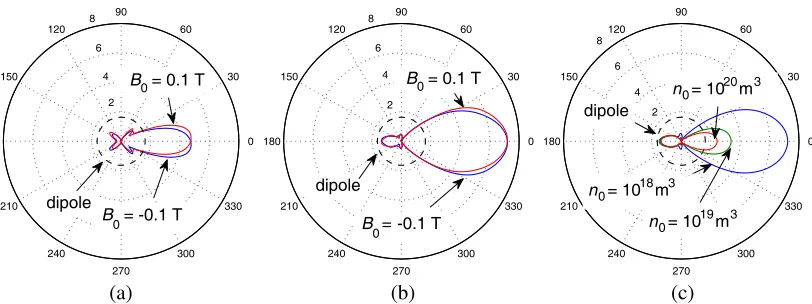
non-reciprocal (Section 2.3). The gain functions g(90◦, φ) for “plasma window 2” and “plasma window 5” are plotted in Figs. 6(a) and 6(b) forB0 =±0.1 T. As can be seen, the main lobe tilts in a clockwise or
counter-clockwise direction, depending on the orientation of B0. Furthermore, simulations carried out
for smaller values of the magnetizing field, e.g., B0 = 0.05 T, show the appearance of a similar, though
reduced squint angle. Thus, all in all this phenomenon adds further flexibility to the beam-forming and beam-steering properties of the PAA.
2 4
6 8
30
210
60
240 90
270 120
300 150
330
180 0
plasma window 5 plasma window 2
dipole
(a) (b) (c)
Figure 5. Reconfigurable PAA: (a) Antenna gain g(90◦, φ) for the configurations shown in Figs. 2(c) and 2(d) and B0 = 0, ne = 1018m-3; (b), (c) 3-D radiation pattern |Es(θ, φ)|/|Es(θ, φ)|max for the
2 4 6 8 30 210 60 240 90 270 120 300 150 330 180 0
B0 = 0.1 T
B
0 = -0.1 T dipole 2 4 6 8 30 210 60 240 90 270 120 300 150 330 180 0
B0 = -0.1 T
B0 = 0.1 T
dipole 2 4 6 8 30 210 60 240 90 270 120 300 150 330 180 0
n0 = 1020 m 3 dipole
n0 = 1018 m 3
n0 = 1019 m 3
(a) (b) (c)
Figure 6. Reconfigurable PAA: (a), (b) Effect of a static magnetic field on the antenna gain g(90◦, φ) for the configurations shown in Figs. 2(c) and 2(d), respectively, and ne = 1018m-3; (c) Effect of the plasma density on the antenna gain g(90◦, φ) for the configuration of Fig. 2(d) andB0= 0.
Finally, we have investigated the behaviour of the gain function for different values of the plasma densityne; though, we only report results for the configuration “plasma window 5.” At higher densities ne ∈ {1019,1020}m-3, the plasma frequency ω
pe and the collision frequency νe increase (Section 2.3) and hence the discharges tend to behave ever more similarly to a lossy conducting medium at the operational frequency f = 2.27 GHz. As a consequence, the screening and guiding effects of the active discharges become more pronounced. Nevertheless, this does not seem to further improve the gain in xOyplane. On the contrary, it is seen from Fig. 6(c) that the main lobe becomes smaller, as the plasma density is increased. Actually, the corresponding 3-D RP (omitted due to space limitations) shows that at higher densities the PAA “plasma window 5” radiates substantially in an angular region around the z-axis. This may be partly due to the fact that, the plasma being denser, the guiding effect of the discharges along the z-direction prevails over the similar phenomenon occurring towards the positive x-direction (normal to the “window”). In addition, as the plasma losses are larger for higher densities, the maximum gain may be reduced because more power is absorbed by the active discharges.
3.2. Antenna Impedance and Power
To examine the behavior of this PAA as a circuit element, in Table 1 we have listed the input impedances (Z) of all the configurations analyzed in this paper; the impedance of the dipole alone (i.e., all plasma discharges switched off) is included for reference. On the whole, the presence of the plasma discharges appears to shift the antenna resonance (with respect to that of the dipole alone, that is) and to reduce the real part ofZ. On the other hand, the effect of an external magnetizing field onZ is only marginal. Interestingly, the configuration “plasma window 5” — which exhibits the best performance in terms of gain — is not resonating atf = 2.27 GHz. Prompted by this finding, we have examined the behaviour of this particular configuration as a function of the operational frequencyf in the range [1, 2.5] GHz for non-magnetized plasma discharges with density ne = 1018m-3. The computed impedance and powers
are plotted in Fig. 7 versus the electric length d/λ0 of the dipole withλ0 the wavelength in free space.
The corresponding quantities relevant to the dipole alone are superimposed for comparison.
It is then apparent from Fig. 7(b) that the PAA of Fig. 2(d) resonates atf ≈2.2 GHz (d/λ0 ≈0.44),
Table 1. Input impedance of the PAA†.
PAA configuration ReZ[Ω] ImZ[Ω] B0[T]
Dipole (all discharges off) 70.56 −7.14 — Plasma on 2 (Fig. 2(a)) 4.69 28.13 0 Plasma on 3 (Fig. 2(b)) 13.64 10.85 0 Plasma window 2 (Fig. 2(c)) 44.14 −5.52 0 Plasma window 2 (Fig. 2(c)) 43.52 −5.93 0.1 Plasma window 2 (Fig. 2(c)) 43.52 −5.93 −0.1 Plasma window 5 (Fig. 2(d)) 25.64 33.36 0 Plasma window 5 (Fig. 2(d)) 25.14 32.99 0.1 Plasma window 5 (Fig. 2(d)) 25.14 33.00 −0.1
†At the operational frequencyf= 2.27 GHz and for a plasma densityne= 1018m-3.
0.2 0.3 0.4 0.5
0 50 100 150 200
d/ 0
Re Z [
]
Plasma window 5
ne = 1018 m 3 B0 = 0
Dipole alone
0.2 0.3 0.4 0.5
400 300 200 100 0 100 200
d/ 0
Im Z [
]
Plasma window 5
ne = 1018 m 3 B0 = 0
Dipole alone
0.2 0.3 0.4 0.5
0 5 10 15 20 25 30 35
d/ 0
Power [mW]
Pin
Prad
Pin
Dipole alone Plasma window 5
ne = 1018 m 3 B0 = 0
λ λ λ
Ω Ω
(a) (b) (c)
Figure 7. Reconfigurable PAA: Impedance and powers as a function of the electric length of the dipole for the configuration “plasma window 5” shown in Fig. 2(d); (a) Real part; (b) Imaginary part, and (c) input and radiated powers when the PAA is energized withVG= 1 V in the delta-gap model of the
feed.
forcing term and therefrom we derive the current flowing in the antenna port, and hence the approach yields the admittanceY = 1/Z as the “natural” circuit parameter. The calculations indicate that, for the case under study,ReY atf = 2.2 GHz is indeed larger than the corresponding value for the solitary dipole. Therefore, the fact that we compute the input power through the formula Pin:= ReY|VG|2/2
reconciles the results of Figs. 7(a) and 7(c).
Last but not least, we notice from Fig. 7(c) that the radiated powerPrad obtained by computing
the flux of the Poynting vector through the sphere at infinity is equal to the input power for all practical purposes, and this means that the plasma, though collisional, has negligible losses atne= 1018m-3. The latter conclusion also applies to the remaining configurations, wherefrom it follows that the efficiency η=Prad/Pinof the PAA is very close to unity. This definition does not factor in other “losses” such as,
e.g., the power required to energize the discharges (see [12] for an experimental setup), but this analysis is outside the scope of the paper.
4. CONCLUSION AND OUTLOOK
The feasibility of this PAA is predicated on the realization of cylindrical-shaped plasma discharges that achieve the desired density in the prescribed range of neutral pressure. As mentioned in Section 1, plasma discharges can be generated in different ways, and the most common approaches include capacitive, inductive, wave-heated, and DC discharges [29], which work in different pressure ranges, and may have natural density limits for efficient power transfer to the plasma. An early prototype of the PAA could be made out of commercial fluorescent lamps, which rely on DC excitation. Although the latter may produce noise, this can be reduced through a pulsing technique, whereby the plasma is generated by extremely short bursts of direct current [5]. Still, another downside of fluorescent lamps is the high pressure (> 103mTorr) of the gas inside the tube; this quantity cannot be controlled and degrades the performance of the PAA. Therefore, in a practical setup the plasma discharges can be realized by coupling RF power capacitively or inductively. Specifically, the plasma can be generated by means of a couple of ring electrodes, which are wrapped around the external surface of the glass tube that contains the gas and are fed with high-voltage (3 kV) RF power (e.g., [12]). In this way, density values of 1018m-3 can be attained with less than 100 W of power and neutral pressure in the range of 30 mTorr.
Finally, future research may include assessing the effect of the length and radius of the plasma discharges. Also, it may be worth investigating whether for a given number of plasma tubes, an optimal placement exists that can maximize the gain in a given direction. Work is under way to explore the effect on the RP of plasma inhomogeneity and actual profiles of an external magnetic field.
ACKNOWLEDGMENT
The Authors acknowledge the CINECA (www.cineca.it/en) award under the ISCRA initiative, for the availability of high performance computing resources and support. Besides, the Authors would like to thank the Reviewers for their appreciation and useful remarks.
REFERENCES
1. Balanis, C. A.,Antenna Theory: Analysis and Design, 2nd Edition, John Wiley & Sons, Inc., New York, 1997.
2. King, R. W. P., The Theory of Linear Antennas, Harvard University Press, Cambridge, MA, 1956. 3. Kumar, R. and D. Bora, “Wireless communication capability of a reconfigurable plasma antenna,”
Journal of Applied Physics, Vol. 109, 063303, 2011.
4. Manheimer, W., “Plasma reflectors for electronic beam steering in radar systems,” IEEE Transactions on Plasma Science, Vol. 19, No. 6, 1128, 1991.
5. Alexeff, I., T. Anderson, S. Parameswaran, E. Pradeep, J. Hulloliand, and P. Hulloli, “Experimental and theoretical results with plasma antennas,” IEEE Transactions on Plasma Science, Vol. 34, April 2006.
6. Grewal, G. and G. Hanson, “Optically-controlled solid-state plasma leaky-wave antenna,”
Microwave Opt. Lett., Vol. 39, 450–453, 2003.
7. Kang, W., M. Rader, and I. Alexeff, “A conceptual study of stealth plasma antenna,” 23rd IEEE International Conference on Plasma Science, No. 4IP07, Boston, MA, USA, June 1996.
8. Moisan, M. and Z. Zakrzewski, “Plasma sources based on the propagation of electromagnetic surface waves,” J. Phys. D, Appl. Phys., Vol. 24, 1025–1084, 1991.
9. Borg, G., J. Harris, D. Miljak, and N. Martin, “Application of plasma coulmns to radiofrequency antennas,”Applied Physics Letters, Vol. 74, 3272–3274, May 1999.
10. Borg, G., J. Harris, N. Martin, D. Thorncraft, R. Milliken, D. Miljak, B. Kwan, T. Ng, and J. Kircher, “Plasma as antennas: Theory, experiment and applications,”Physics of Plasmas, Vol. 7, 2198–2202, May 2000.
11. Stix, T., Plasma Waves, Springer-Verlag, NewYork Inc., 1992.
13. Melazzi, D., V. Lancellotti, M. Manente, D. Pavarin, and T. Anderson, “Numerical investigation into the performance of a reconfigurable gaseous plasma antenna,” 8th European Conference on
Antennas and Propagation (EuCAP 2014), The Hague, The Netherlands, April 2014.
14. Melazzi, D., V. Lancellotti, M. Manente, D. Pavarin, and T. Anderson, “An integral-equation approach to the analysis and design of plasma antennas,” 15th Int. Conf. on Electromagnetics in Advanced Applications (ICEAA ’13), Torino, Italy, 716–719, September 2013.
15. Li, X. and B. Hu, “FDTD analysis of a magneto-plasma antenna with uniform or nonuniform distribution,”IEEE Antennas and Wireless Propagation Letters, Vol. 9, 175–178, 2010.
16. Fernandez-Olvera, A. D. J., D. Melazzi, and V. Lancellotti, “Numerical analysis of reconfigurable plasma antenna arrays,” 9th European Conference on Antennas and Propagation (EuCAP 2015), Lisbon, Portugal, April 2015.
17. Wu, X., J. Shi, Z. Chen, and B. Xu, “A new plasma antenna of beam-forming,” Progress In Electromagnetics Research, Vol. 126, 539–553, 2012.
18. Kuz’min, G., I. M. K. Rukhadze, V. Tarakanov, and O. Tikhonevich, “Reflector plasma array antennas,”J. of Communications Technology and Electronics, Vol. 57, No. 5, 536–542, 2012. 19. Ja’afar, H., M. T. B. Ali, A. N. B. Dagang, H. M. Zali, and N. A. Halili, “A reconfigurable monopole
antenna with fluorescent tubes using plasma windowing concepts for 4.9-GHz application,” IEEE Transactions on Plasma Science, Vol. 43, 815–820, March 2015.
20. Yamamoto, T. and T. Kobayashi, “A reconfigurable antenna using fluorescent lamps,”International
Symposium on Antennas and Propagation (ISAP 2014), Kaohsiung, Taiwan, December 2014.
21. Hansen, R. C., Microwave Scanning Antennas, Vol. 3. Academic Press, New York and London, 1966.
22. Amitay, N., V. Galindo, and C. P. Wu, Theory and analysis of Phased Antenna Arrays, Wiley-Interscience, New York, 1972.
23. Fernandez-Olvera, A. D. J., D. Melazzi, and V. Lancellotti, “Parametric study of a reconfigurable plasma antenna array with linear embedding via Green’s operators,”International Conference on Electromagnetics in Advanced Applications (ICEAA 2015), Turin, Italy, September 2015.
24. Lancellotti, V., B. P. de Hon, and A. G. Tijhuis, “An eigencurrent approach to the analysis of electrically large 3-D structures using linear embedding via Green’s operators,” IEEE Trans. Antennas Propag., Vol. 57, 3575–3585, November 2009.
25. Lancellotti, V. and A. G. Tijhuis, “Extended linear embedding via Green’s operators for analyzing wave scattering from anisotropic bodies,” International Journal of Antennas and Propagation, 11 pages, Article ID 467931, 2014.
26. Lancellotti, V. and D. Melazzi, “Hybrid LEGO-EFIE method applied to antenna problems comprised of anisotropic media,” Forum in Electromagnetic Research Methods and Application Technologies (FERMAT), Vol. 6, 2014, www.e-fermat.org.
27. Lancellotti, V., B. P. de Hon, and A. G. Tijhuis, “Scattering from large 3-D piecewise homogeneous bodies through linear embedding via Green’s operators and Arnoldi basis functions,” Progress In Electromagnetics Research, Vol. 103, 305–322, April 2010.
28. Swanson, D.,Plasma Waves, Institute of Physics, 2nd Edition, 2003.