Design Evolution of a Diesel Engine Piston
Pedireddla Srinu#1 &Mr.V.Tirupathi Rao#2#1M.Tech Scholar(CAD/CAM), Department Of Mechanical Engineering,
Gonna Institute Of Information Technology and Sciences, Visakhapatnam, AP, India.
#2Assistant Professor, Department Of Mechanical Engineering,
Gonna Institute Of Information Technology and Sciences, Visakhapatnam, AP, India. ABSTRACT
A piston is a major component of to and fro motion engines. It transfers the power form expanding gases in the cylinder to the crank shaft through the con rod. Now a three dimensional solid model of piston along with different dimensions is designed with the help of AutoCAD software. By
applying the same pressures and
temperatures for different Piston head diameter with the help of AutoCAD and Ansys 16.0 Software, we can get the evaluated results of von-misses stresses, thermal flux, and thermal gradient and directional deformations for that piston design. General materials for the piston is Structural steel, cast steel, forged steel, Aluminum alloys, and Nickel alloys. In our project Cast Aluminum alloy is used as piston material. It is an excellent material in thermal conductivity and also light in weight. The stress analysis results also help us to improve component design and also have given us the knowledge on the deformation and thermal handling sections on the piston.
Key Words: Diesel Engine, Piston, Piston head, Heat Transfer, Simulation, Structural and Thermal analysis.
1. INTRODUCTION
February 2019
2.
RELATED WORK
In the recent past, the demand for diesel engines has increased rapidly. This is mainly because of their higher thermal efficiency, better performance and reliability. In the earlier days, diesel engines were considered aspollutants compared to petrol/gasoline engines. Later, with the continuous improvements in the technology, there is a considerable reduction in the emission levels in diesel engines. The efforts are continuing in the direction of improving the overall engine performance. Here we have emphasized on the design of the Piston where all the process of conversion of chemical energy to heat energy and then to
mechanical energy takes place. The study of the effect of different Piston diameters on the Thermal loads and the Mechanical stresses are studied. We have chosen the piston head diameter randomly from the previous studies so that a study could be done on the specific area.
3. MATERIAL PROPERTIES
As compared with the previous materials used for the manufacturing of a Piston, we can choose cast aluminium alloy for the current material. We can see that the tensile yield strength and the compressive yield strength are good and it is a very light weight and corrosion resistant. It has a very good life as a Piston material.
Cast Aluminum Alloy Physical Properties Metric
Density 2650kg/m3
Mechanical Properties Metric Tensile strength,Ultimate 850Mpa Tensile Strength,Yield 530 MPa
CTE, linear 18μm/m‐ °C
Specific Heat Capacity 0.461kJ/kg‐ °C Thermal Conductivity 228 W/m‐ K Melting Point 1370‐ 1630°C
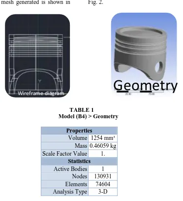
4. GEOMETRY
The image below shows the geometry of the piston as described in the Literature. The piston created in AutoCAD is imported to Ansys software for further analysis. The following types of boundary conditions re-applied. In this geometry, the pressures are applied on the top of the piston and the temperatures are applied on the whole body.In this section ANSYS 16.0 was
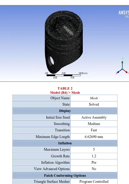
preferred. The mesh generated is shown in Fig. 2.
TABLE 1
Model (B4) > Geometry
Properties
Volume 1254 mm³ Mass 0.46059 kg Scale Factor Value 1.
Statistics
Active Bodies 1 Nodes 130931 Elements 74604 Analysis Type 3-D
4.1 FINITE ELEMENT MODEL This is performed by using computer aided design software. The main objective is to analyze the thermal stress distribution of piston at the combustion process. The analysis is performed to reduce the stress on
the head of the piston. With the help of computer aided design software the structural model of a piston is designed. The finite element analysis is done using ANSYS software .
February 2019
TABLE 2 Model (B4) > Mesh
Object Name Mesh
State Solved
Display
Initial Size Seed Active Assembly
Smoothing Medium
Transition Fast
Minimum Edge Length 6.62690 mm
Inflation
Maximum Layers 5
Growth Rate 1.2
Inflation Algorithm Pre
View Advanced Options No
Patch Conforming Options
Advanced
Number of CPUs for
Parallel Part Meshing Program Controlled
Shape Checking Standard Mechanical
Element Midside Nodes Program Controlled
Straight Sided Elements No
Number of Retries Default (4)
Extra Retries For
Assembly Yes
Rigid Body Behavior Dimensionally Reduced
Mesh Morphing Disabled
Defeaturing
Statistics
Nodes 130931
Elements 74604
Mesh Metric None
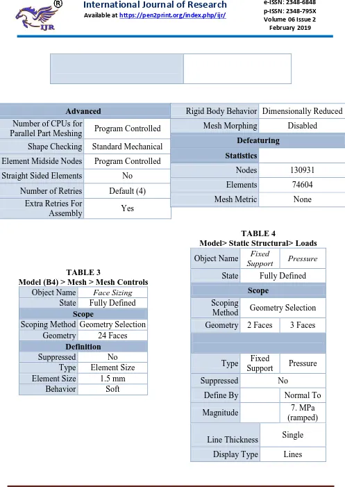
TABLE 3
Model (B4) > Mesh > Mesh Controls
Object Name Face Sizing
State Fully Defined
Scope
Scoping Method Geometry Selection Geometry 24 Faces
Definition
Suppressed No
Type Element Size Element Size 1.5 mm
Behavior Soft
TABLE 4
Model> Static Structural> Loads
Object Name Fixed
Support Pressure
State Fully Defined
Scope
Scoping
Method Geometry Selection
Geometry 2 Faces 3 Faces
Type Fixed
Support Pressure
Suppressed No
Define By Normal To
Magnitude 7. MPa
(ramped)
Line Thickness Single
February 2019
5. CALCULATIONS
The initial volume is 1200cc of air at about 1 atm pressure and 30°C (303.15K), and the
compression ratio is 15:1 (i.e., you’ll compress the air down to 80 cc, which is 1/16-th of the
original volume), let's find out what the resulting temperature and pressure will be.1200cc of air
is 0.0012 cubic meter. At room temperature and 1 Atm pressure it is roughly .048 moles.
5.1 CALCULATIONS FOR THE 70MM PISTON HEAD DIA
Thermal Calculation:
Piston diameter D = 70 mm
Barrel length L = 79 mm Pressure P₁ = 1.0 bar,
Initial Temperature T1 = 27 + 273 = 300 K Cut-off ratio ρ = 8 / 100 VS
In -Diesel Cycle.
Pressures and Temperatures at Salient Points Now, Cylinder swept volume (Vs),
VS = π /4 D2.L
= (π / 4) x 0.0702 x 0.079 VS = 0.0003040276 m3.
V1 = VS + VC = VS + [VS / (r-1)] = [r /(r-1)] x VS
= [18 / (18-1)] x 0.0003040276 V1 = 0.0003219115 m3.
From the Ideal Gas Law,
P1 = mRT1
m = p1V1 / RT1 [R= Gas constant JK-1mol-1] = [(1x105x 0.0003219115) / (8.3144 x 300)]
m = 0.0003079620 Kg / cycle For the Adiabatic (Isentropic) Process 1-2
P1V1ϒ = p2V2ϒ
(P2 / p1) = (V1 / V2) ϒ =r ϒ [r = Compression ratio for diesel engine=10 - 18]
P2 = p1. rϒ = (1 x 181.4) P2 = 57.198 bar.
(T2 / T1) = (V1 /V2) ϒ-1 (r) ϒ-1 = (18)1.4-1
T2 = 953.301 K. V2 = VC = [VS / (r-1)]
= [(0.0003040276/ (18-1)]
V2 = 0.00001884 m3.
% Cut-off ratio = [(ρ-1) / (r-1)]
8/100 = [(ρ-1) / (18-1)]
ρ = (0.08 x 17) + 1 ρ = 2.36.
V3 = ρ. V2
= 2.36 x 0.000017884
V3 = 0.000042206 m3.
For the Constant Pressure Process 2-3
(V3 / T3) = (V2/ T2) T3 = (T2 x V3) / V2
= (953.30145 x 0.000042206) / 0.000017884
T3 = 2249.7914 K.
For the Isentropic Process 3-4
P3V3ϒ = p4V4ϒ
P4 = P3 x (V3 / V4) ϒ-1
= P3 x 1 / (7.627) 1.4 P4 = 3.327 bar. T4 / T3 = (V3 / V4) ϒ-1
(1 / 7.627) 1.4-1 = 0.44366. T4 = T3 x 0.44366 T4 = 998.1556 K
V4 = V1 = 0.0003219115 m3.
Mean Effective Pressure
Pm = [p1 (r) ϒ [ϒ (ρ-1) – r1- ϒ (ρ x ϒ)] / [(ϒ-1) (r-1)]
= {57.198 1 x (18)1.4 [1.4 (2.36-1) – (18)1-1.4 (2.36 x 1.4)]} / [(1.4-1) (18 – 1)] = 57.198 x 1.904 – [0.3146 x (3.327 -1)] / (0.4x 17)
= 8.411x (1.904 – 0.732) Pm = 9.8498 bar
Power of the Engine, P
Work done per cycle = pm X VS
= (9.849 x 0.0003040276 x 105) / 103 = 0.002994 KJ / cycle.
February 2019
= (0.002994 x 380) / 60 Power of the engine = 1.869 KW.
Design Calculation.
Thickness of the Piston Head According to Grashoff’s formula the thickness of the piston head is given by
th = D√(3pmax/16σt)
Where, σt = 1200 M Pa [σt= Tensile Strength for Cast Aluminum] th = 70 x √(3 x 57.198)/(16 x 1200)
th = 6.61 mm.
The maximum thickness from the above formula is th is 6.61 mm. Thickness of the piston head
by heat transfer, considering piston as a circular plate.
th = H/(12.56 k x (Tc - Te)) [(Tc - Te) = 220o c]
[K = Heat conductivity Factor = 49 w/m/oC] [Tc = Temperature at the skirt Centre] [Te =Temperature at the skirt Edge] [H = Heat flow through the head]
H = C x HCV x m x B.P.
[m = fuel mass = 162.8970 x 10⁶ Kg /B.P/sec] [C = Constant value = 0.05]
[HCV = Higher calorific Value = 45 x 103kj/kg] H = 0.05 x 45 x 103 x 162.8970 x 106 x 1.869
H = 0.692 KW. = 692 W. th = 692/(12.56 x 49 x 220)
= 0.00511090 m. th = 5.110 mm.
Taking the larger of the two values, we shall adopt th= 6.61 mm. Radial thickness of the ring (t1)
t1 = D √ (3pw / σt)
t1 = 70√ (3 x 0.742) / (1200) [pw = Pressure at cylinder wall = 0.742 N/MM2]
t1 = 3.027 mm.
Axial thickness of the ring (t2)
t2 = 0.85t1 to t1
Width of the Top Land (b1)
b1 = 1.2 x 6.61 b1 = 7.932mm ≈ 7.9 mm.
Width of the Ring (b2)
b2 = 0.75 t2
b2 = 0.75 x 2.57 b2 = 1.925 mm ≈ 2 mm.
Piston barrel thickness (b)
t3 = 0.03D + b + 4.5 mm
b = t1 + 0.4 b = 3.027 + 0.4
b = 3.427 mm.
t3 = 0.03(70) + 3.427+ 4.5 mm
t3 = 10.027 mm ≈
10.1mm.
Piston Wall Thickness (t4)
t4 = 0.33 x t3
t4 = 0.33 x 10.1
t4 = 3.333 mm.
Skirt Length (l)
l = (0.6 D to 0.8 D)
= 0.65 x 70
l = 49mm.
Total Length of the Piston (L)
L = Skirt Length + ring section Length + Top Land
L = 49 + 10.1 + 7.9
L = 67mm.
Centre of the skirt above the Centre of the skirt
= 0.04 x D
= 0.04 x 70 = 2.8 mm.
Gudgeon pin length in the con-rod bushing (l1)
l1 = 45% of the piston
diameter
= 0.45 x 70
l1 = 31.5mm.
Gudgeon pin diameter (do)
do = (0.28 D to 0.38 D) = >0.34 x 70 =>do=23.8 mm.
5.2 CALCULATIONS FOR THE 110MM PISTON DIAMETER
Thermal Calculation:
Piston dia D = 110 mm Barrel length S = 110 mm,
Pressure P₁ = 1.0 bar, Initial Temperature T1 = 27 + 273 = 300 K Cut-off ratio ρ = 8 / 100 VS
In -Diesel Cycle.
Pressures and Temperatures at Salient Points Now, Stroke volume,
February 2019
= (π / 4) x 0.110 2 x 0.110
VS = 0.00104536495548 m3.
V1 = VS + VC = VS + [VS / (r-1)] = [r /(r-1)] x VS
= [18 / (18-1)] x 0.00104536495548 V1 = 0.00110685701168 m3.
From the Ideal Gas Law
P1 = mRT1 m = p1V1 / RT1
= [(1x105x 0.00110685701168) / (287 x 300)] m = 115.699 Kg / cycle
For the Adiabatic (Isentropic) Process 1-2
P1V1ϒ = p2V2ϒ
(P2 / p1) = (V1 / V2) ϒ =r ϒ P2 = p1. rϒ = (1 x 181.4)
P2 = 57.198 bar.
(T2 / T1) = (V1 /V2) ϒ-1 (r) ϒ-1 = (18)1.4-1 (r) ϒ-1 = 3.1776. T2 = (T1x 3.1776)
T2 = 953.301 K.
V2 = VC = [VS / (r-1)]
= [(0.00104536495548 / (18-1)]
V2 = 0.00002597792748 m3.
% Cut-off ratio = [(ρ-1) / (r-1)]
8/100 = [(ρ-1) / (18-1)] ρ = (0.08 x 17) + 1 ρ = 2.36.
V3 = ρ. V2
= 2.36 x0.00002597792748
V3 = 0.00006130790885 m3.
For the Constant Pressure Process 2-3 (V3 / T3) = (V2/ T2) T3 = (T2 x V3) / V2
= (953.30145 x 0.00006130790885) /0.00002597792748
T3 = 2249.7914 K.
P3V3ϒ = p4V4ϒ
P4 = P3 x (V3 / V4) ϒ-1
= P3 x 1 / (7.627) 1.4 P4 = 3.327 bar. T4 / T3 = (V3 / V4) ϒ-1
(1 / 7.627) 1.4-1 = 0.44366. T4 = T3 x 0.44366 T4 = 998.1556 K
V4 = V1 = 0.00079492458112 m3.
Theoretical Air Standard Efficiency
ɳ diesel = 1-{1 / ϒ (r) ϒ-1 [(ρ ϒ – 1) / ρ -1]}
= 1- {1 / 1.4 (18)1.4-1 [(2.361.4 – 1) / (2.36 – 1)]} = 1 – [(0.22478 x 2.327) / 1.36] = 0.6153.
= 0.6153 x 100 % ɳ diesel = 61.53%
Mean Effective Pressure
Pm = [p1 (r) ϒ [ϒ (ρ-1) – r1- ϒ (ρ x ϒ)] / [(ϒ-1) (r-1)]
= {57.198 1 x (18)1.4 [1.4 (2.36-1) – (18)1-1.4 (2.36 x 1.4)]} / [(1.4-1) (18 – 1)] = 57.198 x 1.904 – [0.3146 x (3.327 -1)] / (0.4x 17)
= 8.411x (1.904 – 0.732) Pm = 9.8498 bar
Power of the Engine, P
Work done per cycle = pm X VS
= (9.849 x 0.0003040276 x 105) / 103 = 0.002994 KJ / cycle.
Work done per second = Work done per cycle x no. of cycles per second = (0.002994 x 380) / 60
Power of the engine = 1.869 KW.
Design Calculation.
Thickness of the Piston Head According to Grashoff’s formula the thickness of the piston head is given by
th = D√(3pmax/16σt)
Where, σt = 1200 M Pa [σt= Tensile Strength for Cast Aluminum] th = 110 x √(3 x 57.198)/(16 x 1200)
February 2019
The maximum thickness from the above formula is th is 10.339mm.
Thickness of the piston head by heat transfer, considering piston as a circular plate.
th = H/(12.56 k x (Tc - Te)) [(Tc - Te) = 220o c]
[K = Heat conductivity Factor = 49 w/m/oC] [Tc = Temperature at the Centre of the skirt] [Te =Temperature at the Edge of the skirt] [H = Heat flow through the head]
H = C x HCV x m x B.P.
[m = Fuel Mass = 162.8970 x 10⁶ Kg /B.P/sec] [C = Constant = 0.05]
[HCV = Higher calorific Value =45 x 103kj/kg] H = 0.05 x 45 x 103 x 162.8970 x 106 x 1.869
H = 0.692 KW. = 692 W. th = 692/(12.56 x 49 x 220)
= 0.00511090 m. th = 5.110 mm.
Taking the larger of the two values, we shall adopt th= 10.339 mm.
Radial thickness of the ring
t1 = D √ (3pw / σt) [pw = Pressure on the gas cylinder wall = 0.742 N/MM2] t1 = 110√ (3 x 0.742) / (1200)
t1 = 4.7376 mm
Axial thickness of the ring
t2 = 0.85t1 to t1 = 0.85 x 4.7376 t2 = 4.026 mm. Width of the Top Land(b1)
b1 = 1.2 x 10.7376 b1 = 12.88512 mm ≈ 12.9 mm.
Width of Second Ring (b2)
b2 = 0.74 t2 b2 = 0.74 x 4.026
b2 = 3.019 mm ≈ 3.1 mm.
Piston barrel Max thickness (t3)
t3 = 0.03D + b + 4.5 mm
b = 5.1376 mm.
t3 = 0.03(110) + 3.427+ 4.5 mm
t3 = 9.9676 mm ≈ 10 mm.
Piston Wall Thickness t4
t4 = 0.33 x t3
t4 = 0.33 x 10
t4 = 3.289 mm.
Length of the skirt
l = (0.6 D to 0.8 D)
= 0.65 x 110
l = 71.5 mm
Total Length of the Piston
L = Skirt Length + Ring Section Length + Top Land
L = 74.5+ 10 +12.9
L = 97.3676 mm.
Centre of the skirt above the Centre of the skirt
= 0.04 x D
= 0.04 x 110
= 4.4 mm.
Gudgeon pin length in the con-rod bushing
l1 = 45% of the piston diameter = 0.45 x 110
l1 = 49.5 mm
Gudgeon pin diameter (do)
do = (0.28 D to 0.38 D) = 0.34 x 110
do = 37.4 mm.
Based on these calculations, the piston has been designed and the calculated temperatures
has been applied. Therefore, the highest temperature reached in the combustion chamber is
nearly 700°C.
We have given the reference temperature as 303.15 K as it is usual on the roads taken as
February 2019
engine is about 700°C so the working boundary conditions are applied at 700°C. After the
combustion, the temperatures may reach up to 2000°C. Let us check for solution using the
boundary conditions.
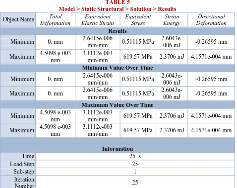
6. RESULTS
After applying the Pressures, the following effects have been resulted.
6.1 Let us look at the figures for various factorson a 70mm piston dia.
Total deformation
Directional deformation
Equivalent Elastic Strain
TABLE 5
Model > Static Structural > Solution > Results
Object Name Total
Deformation
Equivalent Elastic Strain
Equivalent Stress
Strain Energy
Directional Deformation Results
Minimum 0. mm 2.6415e-006
mm/mm 0.51115 MPa
2.6043e-006 mJ -0.26595 mm
Maximum 4.5098 e-003 mm
3.1112e-003
mm/mm 619.57 MPa 2.3706 mJ 4.1571e-004 mm
Minimum Value Over Time
Minimum 0. mm 2.6415e-006
mm/mm 0.51115 MPa
2.6043e-006 mJ -0.26595 mm
Maximum 0. mm 2.6415e-006
mm/mm 0.51115 MPa
2.6043e-006 mJ -0.26595 mm
Maximum Value Over Time
Minimum 4.5098 e-003 mm
3.1112e-003
mm/mm 619.57 MPa 2.3706 mJ 4.1571e-004 mm
Maximum 4.5098 e-003 mm
3.1112e-003
mm/mm 619.57 MPa 2.3706 mJ 4.1571e-004 mm
Information
Time 25. s
Load Step 25
Sub-step 1
Iteration
February 2019
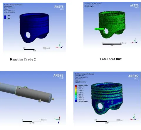
6.2 Results for the effect of temperature on the 70mm dia Piston.
TABLE 6
Model> Steady-State Thermal > Solution> Results Temperatur
e
Reaction Probe
Object Name Temperature Total Heat Flux
State Solved
Scope
Scoping Method Geometry Selection
Geometry All Bodies
Definition
Type Temperature Total Heat Flux By Time Of Maximum Time Identifier
Suppressed No
Display Time Last
Calculate Time History Yes
Results
Minimum 1. s 1.5922e-014 W/mm²
Maximum 1. s 1.6864e-011 W/mm²
Integration Point Results
Display Option Averaged
Average Across Bodies No
Minimum Value Over Time
Minimum 9.696e-015 W/mm²
Maximum 2.3555e-014 W/mm²
Maximum Value Over Time
Minimum 1.6864e-011 W/mm²
Maximum 1.6864e-011 W/mm²
Information
Time 25. s
Load Step 25
Sub-step 1
Iteration Number 25
Model> Steady-State Thermal > Solution> Probes
Object Name Reaction Probe Reaction Probe 2
State Solved
Definition
Type Reaction
Location Method Boundary Condition Boundary Condition Temperature Convection
February 2019
Options
Display Time End Time
Results
Heat 1.5349e-002 W -1.5349e-002 W
Maximum Value Over Time
Heat 1.5349e-002 W -1.5349e-002 W
Minimum Value Over Time
Heat 1.5349e-002 W -1.5349e-002 W
6.3 LET US LOOK AT THE FIGURES FOR VARIOUS FACTORS LIKE TOTAL
DEFORMATION, STRESSES ETC ON A 110MM PISTON DIAMETER.
Equivalent stress
Total deformation
February 2019
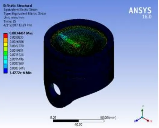
Equivalent Elastic Strain
TABLE 7
Model > Static Structural > Solution > Results
Object Name Total
Deformation
Equivalent Elastic Strain
Equivalent Stress
Strain Energy
Directional Deformation Results
Minimum 0. mm 1.4272e-006
mm/mm 0.23675 MPa
7.0451e-007 mJ -0.42205 mm
Maximum 5.098 e-003 mm
3.4461e-003
mm/mm 688.09 MPa 3.5185 mJ 6.6003e-004 mm
Minimum Value Over Time
Minimum 0. mm 1.4272e-006
mm/mm 0.23675 MPa
7.0451e-007 mJ -0.42205 mm
Maximum 0. mm 1.4272e-006
mm/mm 0.23675 MPa
7.0451e-007 mJ -0.42205 mm
Maximum Value Over Time
Minimum 5.098 e-003 mm
3.4461e-003
mm/mm 688.09 MPa 3.5185 mJ 6.6003e-004 mm
Maximum 5.098 e-003 mm
3.4461e-003
mm/mm 688.09 MPa 3.5185 mJ 6.6003e-004 mm
Information
Time 25. s
Load Step 25
Sub-step 1
Number
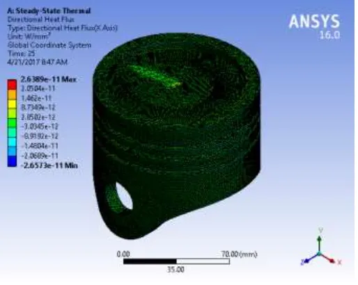
6.4The following are the results for the effect of temperature on the 110mm dia Piston.
6.5
Total heat flux
Reaction Probe
February 2019
TABLE 8
Model > Steady-State Thermal > Solution > Results
Object Name Temperature Total Heat Flux Directional Heat Flux Thermal Error Results
Minimum 950. K 9.5696e-015 W/mm² -2.6573e-011 W/mm² 9.6623e-023 Maximum 950. K 3.5375e-011 W/mm² 2.6389e-011 W/mm² 3.2103e-018
Minimum Value Over Time
Minimum 950. K 9.117e-015 W/mm² -2.6573e-011 W/mm² 6.2327e-023 Maximum 950. K 1.1645e-014 W/mm² -2.6573e-011 W/mm² 9.7432e-023
Maximum Value Over Time
Minimum 950. K 3.5375e-011 W/mm² 2.6381e-011 W/mm² 3.208e-018 Maximum 950. K 3.5375e-011 W/mm² 2.6389e-011 W/mm² 3.2105e-018
Information
Time 25. s
Load Step 25
Sub-step 1
Iteration Number 25
7. CONCLUSION
looks quite promising. Comparatively, a change in piston design has been made. Here, the excess material of the piston aiding in higher weight has been removed. The stresses and temperatures applied on both of the configurations are under allowed limits. It was found that the design parameter of the piston with these modifications gives us the improvements as expected in the existing results.
8.
REFERENCES
[1]. Alloy data:
http://11.tcdcinc.com/media/2009_NADCA_Alloy_Data.pdf
[2]. Dr. Ahmed A, Dr. Basim., “Thermal effects on diesel engine piston and piston compressionring”, Engineering and technology Journal, Vol. 27, No. 8, 2009.
[3]. Piotrszurgott, TadeuszNiezgoda “Thermo Mechanical FE Analysis Of The Engine Piston Made Of Composite Material With Low Hysteresis”, Journal of KONESpower trains and transport, Vol 18, No 1, 2011.
[4]. http://hyperphysics.phy-astr.gsu.edu/hbase/thermo/diesel.html [5]. https://www.dieselnet.com/tginfo/abstracts.html
9 .ABOUT THE AUTHORS
PEDIREDDLA SRINU is currently pursuing his 2 Years M.Tech in Department Of
Mechanical Engineering, Gonna Institute Of Information Technology and Sciences, Visakhapatnam, AP, India. His area of interest includes CAD/CAM.