October 2018
Available online: https://pen2print.org/index.php/ijr/ P a g e | 529
Thermal Structural of Nozzle Cylindrical Shell Intersection
#1 P.RAGHUPATHI P.G SCHOLAR
#2 B.N SANDEEP ASSISTANT PROFESSOR
DEPARTMENT OF MECHANICAL ENGINEERING
TALLA PADMAVATHI COLLEGE OF ENGINEERING,SOMIDI,WARANGAL,T.S.
ABSTRACT
In this thesis, the effect of nozzle placement on the pressure vessel and nozzle fillet on the basis of stress & temperature distribution is analyzed utilizing FEA software Ansys. The parametric models of the pressure vessel with nozzle at different areas (i.e) nozzle placed at smaller end of cylinder & nozzle placed at centre and each with fillet & without fillet are be done in 3D modelling software Creo 2.0. The Static analysis and Thermal analysis are done on tall the models by applying under internal pressure and temperature to evaluate
deformations, stresses, temperature
distribution respectively using materials
Structural Steel and Aluminum alloy 7075.
I.INTRODUCTION
A nozzle is a tool designed to regulate the direction or characteristics of a fluid flow (especially to extend velocity) because it exits (or enters) an interior chamber or pipe.
PRESSURE VESSEL
A pressure vessel is an instrumentation designed for holding gases or liquids at a pressure differing substantially from ambient pressure.
Nozzles on Heads
After a head is attached to main cylinder or to a nozzle on main cylinder (see below), a nozzle can be attached to head. Pressurised pipings, since the simple structures in chemical industries & nuclear power plants, were special pressure instruments with danger
of explosion.The sphere nozzle & cylinder nozzle (tee) intersections are employed in pressure vessel and piping systems of refineries, power generation plants & chemical plants. Some specific samples of these intersections are nozzles in reactor vessels, liquid storage tanks & pressure vessel heads. Since the Nineteen Sixties in depth analysis has been allotted to work out the linear & non-linear behavior of unbroken intersections
under pressure loading.
II.LITERATURE SURVEY
A.Y.Kuo [1], 2 unremarkably crossed
cylinders below totally different internal pressures in every of the cylinders is solved analytically. The inclusion of nozzle fillet, insert plate and inner nozzle broadens the pertinence of this analytical methodology within the design & analysis of pressurised cylinder to cylinder intersection. The present numerical answer theme has been incorporated
within the coding system Nutshell.
Comparisons of Nutshell solutions &
experimental or finite component results have
conjointly been conferred. K. Vijaya Krishna
Varma and V.S.V Sai Sumanth [2], analyzed
the material effect with respect to temperature and stress distribution using finite element analysis.
DESIGN PARAMETERS & MODELING OF CYLINDER AND NOZZLE
The design parameters are considered from the journal paper “Structural and thermal analysis
of reinforced nozzle-cylindrical shell
Available online: https://pen2print.org/index.php/ijr/ P a g e | 530
International Journal of Mechanical
Engineering and Technology (IJMET),
Volume 8, Issue 8, August 2017.
DESIGN DATA
Pressure: 0.23 MPa; Displacement: X=0, Y=0, Z=0
Reference temperature: 2200 C. Convection:
Film coefficient: 0.0025 W/mm2.k, Ambient
temperature: 323.15 K
Geometry
Vessel id: 1150 mm s, Shell thickness: 75 mm, Length of vessel: 6200 mm, Pad ID: 280 mm; Pad od: 560 mm, Pad thickness: 72 mm, Nozzle ID: 150 mm; Nozzle thickness: 65 mm, Nozzle height (total): 442.3 mm, Nozzle head dia: 400 mm; Nozzle head thickness: 45 mm
3D MODEL OF THE PRESSURE VESSEL CYLINDER
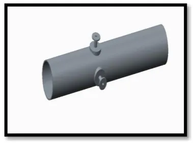
Four pressure vessel cylinder models are modelled in Creo 2.0. One model is with nozzle placed at smaller end & without fillet at nozzle cylinder intersection and second model with fillet at nozzle cylinder intersection. Third model is with nozzle placed at centre of cylinder & without fillet at nozzle cylinder intersection and fourth model with fillet at nozzle cylinder intersection. The dimensions are taken from design parameters. The diameter of cylinder at one end is 575mm (larger end) and diameter at other end is 560mm (smaller end). The nozzle is placed near the larger end in one model and at the smaller end in another model.
Table – Models considered
MODEL1
Nozzle is Placed at smaller end of cylinder & with fillet at cylinder nozzle intersection
MODEL2
Nozzle is Placed at smaller end of cylinder & without
fillet at cylinder nozzle intersection
MODEL3
Nozzle is Placed at centre of cylinder &
with fillet at cylinder nozzle
intersection
MODEL4
Nozzle is Placed at centre of cylinder &
without fillet at cylinder nozzle intersection
Fig 1:-3D Model with nozzle placed at smaller end of cylinder without fillet
Fig 2:-3D Model with nozzle placed at centre of cylinder without fillet
III.ANALYSIS OF CYLINDER WITH NOZZLE
Static Structural analysis and thermal analysis are performed on all models of cylinder (i.e) one with fillet and without fillet & changing nozzle placement on cylinder. The pressure & temperature taken
is considered from the journal paper
October 2018
Available online: https://pen2print.org/index.php/ijr/ P a g e | 531
Mechanical Engineering and Technology (IJMET), Volume 8, Issue 8, August 2017.
The materials considered for analysis are Structural Steel, Aluminum and Copper.
STATIC STRUCTURAL ANALYSIS
Static Structural analysis is done on all the 4 models by changing the boundry condition “displacement” position and materials Structural Steel, Aluminum alloy 7075.
CYLINDER WITH NOZZLE AT
SMALLER END & WITH FILLET
DISPLACEMENT APPLIED AT
SMALLER END
After completing the models in Creo 2.0, they are saved as .igs files. Open Ansys Workbench and select Static Structural
The displacement is specified on the end of cylinder near the nozzle.
Fig 3:-Displacement is applied on one end of cylinder near nozzle placement
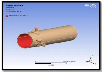
Pressure is applied inside the cylinder.
Fig 4:- Pressure is applied inside the cylinder.
Solve the analysis and Total Deformation, Stress & Strain are taken as results.
Fig 5:-Total deformation of cylinder with nozzle at smaller end & with fillet using
Aluminum 7075
Fig 6:-Strain of cylinder with nozzle at smaller end & with fillet using Aluminum 7075
Fig 7:-Stress of cylinder with nozzle at smaller end & with fillet using Aluminum 7075
Available online: https://pen2print.org/index.php/ijr/ P a g e | 532 Thermal Analysis is performed by applying
temperature of 2200C taken from the
reference journal paper as specified in Design parameters chapter.
Initial Temperature is applied inside the cylinder, Convection is applied on the external surface of cylinder.
Solve the analysis and the results taken are Temperature and Total Heat Flux
Fig 8:-Temperature of cylinder with nozzle at smaller end & with fillet using Aluminum
7075
Fig 9:-Total Heat Flux of cylinder with nozzle at smaller end & with fillet using Aluminum
7075
V.RESULTS & DISCUSSIONS
Static Structural Analysis
Model 1 with displacement applied at smaller end
MATER IAL
DEFORMATI ON(mm)
STR AIN
STRES S(MPa
)
STEEL 0.072723 3.176
4e-5 6.3526
ALUMI NUM
7075
0.21092 8.880
1e-5 6.3045
Model 1 with displacement applied at larger end
By observing above tables the following observations are made:
The deformations and stresses are increasing for the model 1 when the displacement is applied at larger end when compared with that when the displacement is applied at smaller end. The stresses are less when Aluminum 7075 is used. The stresses are increasing when displacement is applied at larger end by about 31% for Steel, by about 32% for Aluminum 7075 when compared with displacement is applied at smaller end.
Model 2 with displacement applied at smaller end
MATERIAL DEFORMA
TION(mm)
STRA IN
STRE SS (MPa
)
STEEL 0.047434 3.270
5e-5
6.540 7
ALUMINUM 0.14042 9.163
2e-5
6.505 5 Model 2 with displacement applied at larger end
MATER IAL
DEFOR MATIO N(mm)
STRAI N
STRESS (MPa)
STEEL 0.75436 4.6427
e-5 9.2601
ALUMI NUM
7075
2.1257 0.0001
October 2018
Available online: https://pen2print.org/index.php/ijr/ P a g e | 533
MATERI AL DEFORMATIO N(mm) STRA IN STRE SS (MPa )
STEEL 0.33052 3.306
5e-5
6.612 4
ALUMIN UM
0.93261 9.268
9e-5
6.580 3 The deformations and stresses are increasing for the model 2 when the displacement is applied at larger end when compared with that when the displacement is applied at smaller end. The stresses are less when Aluminum 7075 is used. The stresses are increasing when displacement is applied at larger end by about 1.08% for Steel, by about 7.48% for
Aluminum 7075 when compared with
displacement is applied at smaller end.
Model 3 with displacement applied at smaller end MATERI AL DEFORMATIO N(mm) STRA IN STRE SS (MPa)
STEEL 0.1986 3.345e
-5
6.665 5
ALUMIN UM
0.56276 9.3678
e-5
6.621 4 Model 3 with displacement applied at larger end MATER IAL DEFO RMA TION( mm)
STRAIN STRES
S (MPa)
STEEL 0.3673
3
3.3329e-5 6.6896
ALUMI NUM
1.0368 9.3554e-5 6.6508
The deformations and stresses are increasing for the model 3 when the displacement is
applied at larger end when compared with that when the displacement is applied at smaller end. The stresses are less when Aluminum 7075 is used. The stresses are increasing when displacement is applied at larger end by about 0.36% for Steel, by about 0.44% for
Aluminum 7075 when compared with
displacement is applied at smaller end.
Model 4 with displacement applied at smaller end MATER IAL DEFORMATI ON(mm) STRAI N STR ESS (MPa )
STEEL 0.088931 3.6715e
-5
7.342 6
ALUMI NUM
0.25465 0.00010
297
7.310 7 Model 4 with displacement applied at larger end MATER IAL DEFOR MATIO N(mm) STR AIN STRESS (MPa)
STEEL 0.14626 3.688
e-5
7.3755
ALUMI NUM
0.41522 0.000
1034 3
7.3429
The deformations and stresses are increasing for the model 4 when the displacement is applied at larger end when compared with that when the displacement is applied at smaller end. The stresses are less when Aluminum 7075 is used. The stresses are increasing when displacement is applied at larger end by about 0.44% for Steel, by about 0.43% for
Aluminum 7075 when compared with
displacement is applied at smaller end.
Thermal Analysis
Available online: https://pen2print.org/index.php/ijr/ P a g e | 534 MATERI
AL
TEMPERATUR E(K)
HEAT FLUX(W/m
m2)
STEEL 493.15 0.21534
ALUMIN
UM 493.15 0.32621
The heat flux value is increasing when Aluminium 7075 is used by 34% when compared with Steel.
Model 2
MATERIAL NAME
TEMPERAT URE(K)
HEAT FLUX(W/m
m2)
STEEL 493.15 0.19625
ALUMINUM 493.15 0.32232
The heat flux value is increasing when Aluminum 7075 is used by 39% when compared with Steel.
Model 3
MATERI AL NAME
TEMPERATUR E(K)
HEAT FLUX(W/m
m2)
STEEL 493.15 0.24723
ALUMIN UM
493.15 0.37508
The heat flux value is increasing when Aluminum 7075 is used by 34% when compared with Steel.
Model 4
MATERI AL NAME
TEMPERATUR E(K)
HEAT FLUX(W/m
m2)
STEEL 493.15 0.19376
ALUMIN UM
493.15 0.32151
The heat flux value is increasing when Aluminum 7075 is used by 40% when compared with Steel.
VI.CONCLUSION
By observing static structural analysis results, the deformations and stresses are increasing for all models when the displacement is applied at larger end when compared with that when the displacement is applied at smaller end. The stresses are less when Aluminum 7075 is used. The Model 1 has higher stress value when Steel is used and less for Model 2 when Aluminum 7075 is used. By observing thermal analysis results, the Model 3 has higher heat flux value when Aluminum 7075 is used and less for Model 4 when Steel is used. The higher heat flux depicts the higher heat transfer values.
REFERENCES
1. A.Y.Kuo and T.Y.Hsu, Stress Analysis of
Reinforced Nozzle-Cylindrical Shell
Intersection Under Internal Pressure or Nozzle Radial Thermal Expansion, Journal of Pressure Vessel Technology, Volume 110, Nov 01, 1988
2. K. Vijaya Krishna Varma and V.S.V
Sai Sumanth, Structural and thermal
analysis of reinforced nozzle-cylindrical shell intersection under internal pressure and nozzle radial thermal expansion”,
International Journal of Mechanical
Engineering and Technology (IJMET), Volume 8, Issue 8, August 2017.
3. Zhifu Sang, Application Of Fem Analysis
Methods To A Cylinder-Cylinder
Intersection Structure , 18th International Conference on Structural Mechanics in Reactor Technology, smirt 18, August 7-12, 2005
4. Andrade, Tatiana Lima, Paula, Wagner
Andrade de, Junior, Pedro Americo
Almeida Magalhaes, Analysis of Stress in
October 2018
Available online: https://pen2print.org/index.php/ijr/ P a g e | 535
Engineering Research and Applications, Vol. 5, Issue 9,September 2015.
5. T.Ahmad, M.A.Khan and D.Redekop,
Pressurised Shell Intersections with Local Area Wall Thinning, Transactions, SMiRT 19, Toronto, August 2007.
6. Iyad Al-Zahamah, Thermal Stresses in
Pipes, School of Mechanical &
Manufacturing Engineering Dublin City University, April 2002.
7. Hein Schmidt, The design of a pressure
vessel and testing procedures for the determination of the effect of high temperature pressurised helium on valve contact welding, School of Mechanical and Materials Engineering, Potchefstroom
University for CHE, 4th April 2004.
8. V.R.Manthenaa, N.K.Lambab,
G.D.Kedara, Thermal stress analysis in a
functionally graded hollow elliptic
cylinder subjected to uniform temperature distribution, Applications and Applied Mathematics: An International Journal (AAM), Vol. 12, Issue 1, June 2017.
9. Navid Nazemi, Behaviour of X60 Line
Pipe under Combined Axial and
Transverse Loads with Internal Pressure, Degree of Master of Applied Science at the University of Windsor, Ontario, Canada, January 15, 2009.
10. Neetu, Design and analysis of multilayer