Available online: https://edupediapublications.org/journals/index.php/IJR/ P a g e | 682
Miniaturization of Rat-race coupler with Harmonic suppression
technique
N
.Sai venkat
1,V.Ravi sekharareddy
2, A.Ravindra
3,Y.Sreekanth
42
Assistant Professor,
1,3,4Student, Department of Electronics and Communication,
Lakireddy Balireddy College of Engineering, Mylavaram, India
Abstract:
In this work, a compact RRC using a T-shaped line configuration, in place of all 90° conventional transmission line sections is presented to achieve broadband suppression of harmonics. A lossless transmission line model is derived for the design. As the design is not composed of any complicated structures, via holes and lumped elements, it is simple to implement and easy to fabricate.
Keywords:
RRC,T-shaped line configuration, harmonics, lumped elements, lossless transmission line
I.
INTRODUCTION
Hybrid directional coupler, recognized as rat-race coupler (RRC), is one of the fundamental components used in microwave integrated circuits (MICs), such as mixers, amplifiers, multipliers, modulators, demodulators, antenna feed networks etc. Besides simplicity, it has broader bandwidth as compared to 90° branch-line coupler, and the isolation between the input ports may be independent of the output termination impedances. However, the conventional coupler consumes significant amount of circuit area especially at low frequencies, due to the required large 540° electrical length transmission line,
usually in circular or rectangular shape. In addition, the conventional coupler has spurious pass-bands at harmonics of the fundamental frequency, which affects the circuit performance when used in wireless
applications. RAT-RACE coupler is a four port network with a 180phase shift between the two output ports and can also be operated in phase at the outputs. It functions widely in the microwave balanced mixer and amplifier [1]. Several methods are proposed to reduce the physical size of a rat-race coupler,such as by use of artificial transmission lines (ATLs) [2] and[3], metamaterial transmission line [4], using λ/8 or λ/6 sections to replace λ/4 traditional sections [5], adding open-circuited stubs [6], [12] double C-section folded line structure [7],three equal arms of arbitrary electrical length [8], adding defected ground structure (DGS) [9], and compensated spiral compact microstrip resonator cells (C-SCMRCs) [10] and substituting transmission lines by periodic stepped-impedance units cells [11]. However, [2]–[8] do not discuss about the harmonic suppression. Consequently, harmonic suppression is discussed in [9]–[12]. In [9], the DGSs introduce a transmission zero at the upper stop band. In [10], the harmonic suppression is achieved by multiple transmission zeros generated by the C-SCMRCs. In [11], the first harmonic of the coupler is adjusted away from the fundamental resonance by adjusting the impedance ratio of the stepped-impedance unit cells. However, there are some shortcomings in [9]–[12], such as the absence of accurate circuit models which add complicities to the design [9], significant dependence on EM simulations [10], and degraded return loss bandwidth [11], [12].
Available online: https://edupediapublications.org/journals/index.php/IJR/ P a g e | 683
Fig. 1. The proposed rat-race coupler. (a) Layout, and (b) Equivalent transmission line model
In this paper, a miniaturized rat-race coupler with harmonic suppression is proposed, demonstrating the rigorous theoretical analysis, simple design procedure, compact size, and excellent in-band and out-of-band performances. The configuration is exhibited in Fig. 1. First of all, the analysis is conducted to show how a stub-loaded transmission line can be used to equivalently replace a quarter-wavelength transmission line at an effective frequency. Then all the quarter-wavelength transmission lines in a traditional rat-race coupler are replaced by their equivalent stub-loaded transmission lines. Therefore, the overall physical size of the coupler is significantly reduced. In addition, the transmission zero introduced by the stubs suppresses the spurious pass bands. Finally, the proposed coupler is fabricated and a good match is found between the predicted and measured results. Adding stubs is very
common in microwave circuit designs. However, to our best knowledge, it is the first time that such a stub-loaded transmission line is studied to replace the quarter-wavelength transmission lines equivalently in the traditional rat-race coupler to realize miniaturization and harmonic suppression.
(a)frequncy(GHz) (b) frequncy(GHz)
Fig2. Simulated S-Parameters of the (a) Conventional race coupler with harmonics (b) Conventional rat-race coupler at f0
II.
ANALYSIS OF RAT RACE COUPLER
The layout and its equivalent transmission line model of the proposed coupler are shown in Fig. 1, where is the characteristic impedance and is the electrical length of the transmission lines at the design
0 2 4 6 8 10
Available online: https://edupediapublications.org/journals/index.php/IJR/ P a g e | 684
frequency. One stub-loaded transmission line is marked by dashed rectangle in Fig. 1(b) and its ABCD
matrix can be derived as
A B
M = C D
---(1)
Where
A = D = cos2θ0 - (1+z1/z2) sin2θ0---(2)
B= jz1(2sinθ0cosθ0-z1/z2sin2θ0tanθ0)---(3)
C=jsinθ0cosθ0((2/z1) +(1/z2))---(4)
In order to match this stub-loaded transmission line to a quarter wavelength transmission line with a characteristic impedance of Z0 A=D=0, B=J Z0 , C=J/ Z0 and . Therefore Z1andZ2 can be worked out as
Z1= Z0cotθ0/2;
Z2= (Z0tan2 θ0)/2;
Fig3. Replacing of RRC with proposed RRC
Available online: https://edupediapublications.org/journals/index.php/IJR/ P a g e | 685
Fig4. Full-wave simulated S-Parameters (S31 and S41) of proposed RRC
Fig5. Full-wave simulated S-Parameters (S11 and S21) of proposed RRC
III.
FABRICATION AND MEASUREMENT
A rat-race coupler operating at 1 GHz with θ0=60, is implemented and fabricated on the substrate with θ0=60 dielectric constant of 2.2 and thickness of 0.508 mm. With and in the conventional rat-race coupler, and are calculated to be and , respectively. The fabricated rat-race coupler with all physical dimensions is exhibited in Fig. 4. The simulated and measured results are plotted together in Figs. 4–6, which agree with each
Fig6. proposed full wave simulated harmonic suppressed compact RRC with dimensions(mm)
Available online: https://edupediapublications.org/journals/index.php/IJR/ P a g e | 686
Fig 9. Full wave frequency response of proposed RRC for the difference port excitation
other very well. At the design frequency 1 GHz, the |s21| and |s31| are -3.67db and-3.23db respectively, the isolation at both port 1 and 4 are better than 50 dB, and phase(s21-s31) and phase(s24-s34) are 00 and1800 respectively. As to the bandwidth, return loss better than 20 dB is obtained from 2.2 to 2.86 GHz (24.5%), and isolation better than 50 dB is achieved from 2.15 GHz to 2.8 GHz (27%). In addition, the transmission zero is introduced by the stubs around 9GHz as expected . As a result, the upper stopband is extended up to9 GHz (9 times of the center frequency) with the suppression level better than 10 dB. The effective circuit area of the proposed rat-race coupler is only
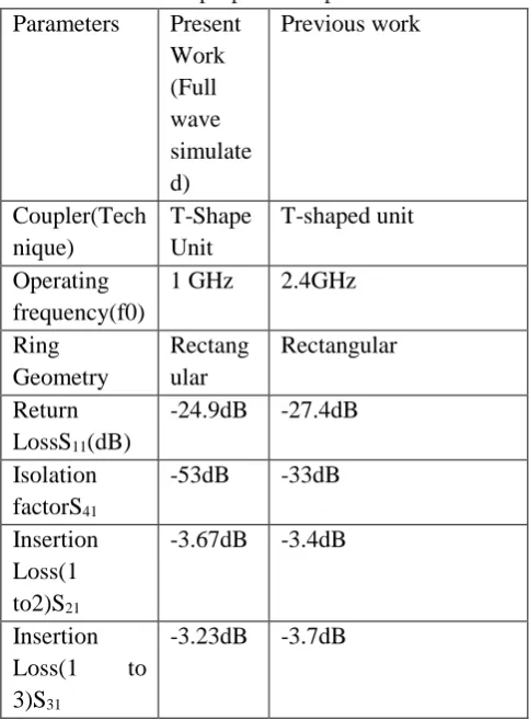
45.1% of that of the conventional rat-race coupler. Table I compares the proposed coupler with some previous publications.
TABLE I
Simulated results of proposed & previous RRC Parameters Present
Work (Full wave simulate d)
Previous work
Coupler(Tech nique)
T-Shape Unit
T-shaped unit
Operating frequency(f0)
1 GHz 2.4GHz
Ring Geometry
Rectang ular
Rectangular
Return LossS11(dB)
-24.9dB -27.4dB
Isolation factorS41
-53dB -33dB
Insertion Loss(1 to2)S21
-3.67dB -3.4dB
Insertion Loss(1 to 3)S31
-3.23dB -3.7dB
IV.
CONCLUSIONAvailable online: https://edupediapublications.org/journals/index.php/IJR/ P a g e | 687
summarized. Finally, the rat-race coupler with Θ =600has been fabricated. Consequently, the overall physical size is significantly reduced, and the harmonic is suppressed by the transmission zero introduced by the stubs. Therefore, our design principle has been verified experimentally.
V.
References
[1] D. M. Pozar, Microstrip Engineering, 3rd ed. New York: Wiley, 2005.
[2] H. Okabe, C. Caloz, and T. Itoh, “A compact enhanced-bandwidth hybrid ring using an artificial lumped-element left-handed transmission- line section,” IEEE Trans. Microw. Theory Tech., vol. 52, no. 3, pp. 798–804, Mar. 2004.
[3] C. H. Tseng and H. J. Chen, “Compact rat-race coupler using shunt-stub-based artificial transmission lines,” IEEE Microw. Wireless Compon. Lett., vol. 18, no. 11, pp. 734–736, Sep. 2008.
[4] G. Sisó, J. Bonache, M. Gil, and F. Martín, “Application of resonant type metamaterial transmission lines to the design of enhanced bandwidth components with compact dimensions,”
Microw. Opt. Technol.Lett., vol. 50, pp. 127–134, Jan. 2008.
[5] D. I. Kim and G. S. Yang, “Design of new hybrid-ring directional coupler using or sections,”
IEEE Trans. Microw. Theory Tech., vol. 39, no. 10, pp. 1779–1784, Oct. 1991.
[6] M. L. Chuang, “Miniaturized ring coupler of arbitrary reduced size,” IEEE Microw. Wireless Compon. Lett., vol. 15, no. 1, pp. 16–19, Jan. 2005.
[7] R. K. Settaluri, G. Sundberg, A. Weisshaar, and V. K. Tripathi, “Compact folded line rat-race hybrid couplers,” IEEE Microw. Guided Wave Lett., vol. 10, no. 2, pp. 61–63, Feb. 2000.
[8] M. K. Mandal and X. S. Sanyal, “Reduced-length rat-race coupler,” IEEE Trans. Microw. Theory Tech., vol. 55, no. 12, pp. 2593–2598,Dec. 2007.
[9] Y. J. Sung, C. S. Ahn, and Y. S. Kim, “Size reduction and harmonic suppression of rat-race hybrid coupler using defected ground structure, ”IEEE Microw. Wireless Compon. Lett., vol. 14, no. 1, pp. 7–9, Jan. 2004.
[10] J. Z. Gu andX.W. Sun, “Miniaturization and harmonic suppression ratrace coupler using C-SCMRC resonators with distributive equivalent circuit,” IEEE Microw. Wireless Compon. Lett., vol. 15, no. 12, pp. 880–882, Dec. 2005.