FSF ALAR Briefing Note
3.1 — Barometric Altimeter and
Radio Altimeter
Flight crews on international routes encounter different units of measurement for setting barometric altimeters, thus requiring altimeter cross-check procedures.
Statistical Data
The Flight Safety Foundation Approach-and-landing Accident Reduction (ALAR) Task Force found that lack of positional awareness was a causal factor1 in 51 percent of 76
approach-and-landing accidents and serious incidents worldwide in 1984 through 1997.2 The task force said that these accidents and
incidents generally involved lack of vertical-position awareness and resulted in controlled flight into terrain (CFIT).
QNH or QFE?
QNH (altimeter setting that causes the altimeter to indicate height above mean sea level [i.e., field elevation at touchdown on the runway]) has the advantage of eliminating the need to change the altimeter setting during operations below the transition altitude/flight level (FL).
QNH also eliminates the need to change the altimeter setting during a missed approach, whereas such a change usually would be required when QFE (altimeter setting that causes the altimeter to indicate height above the QFE reference datum [i.e., zero at touchdown on the runway]) is used.
Some operators set the altimeter to QFE in areas where air traffic control (ATC) uses QNH and the majority of operators use QNH. Standard operating procedures (SOPs) can prevent altimeter-setting errors.
Units of Measurement
The most common units of measurement for setting altimeters are:
• Hectopascals (hPa) [previously referred to as millibars (mb)]; and,
• Inches of mercury (in. Hg).
When in. Hg is used for the altimeter setting, unusual barometric pressures, such as a 28.XX in. Hg (low pressure) or a 30.XX in. Hg (high pressure), may go undetected when listening to the automatic terminal information service (ATIS) or ATC, resulting in a more usual 29.XX altimeter setting being set.
Figure 1 (page 60) and Figure 2 (page 60) show that a 1.00 in. Hg discrepancy in the altimeter setting results in a 1,000-foot error in the indicated altitude.
In Figure 1, QNH is an unusually low 28.XX in. Hg, but the altimeter was set mistakenly to a more usual 29.XX in. Hg, resulting in the true altitude (i.e., the aircraft’s actual height above mean sea level) being 1,000 feet lower than indicated.
Tool Kit
Flight Safety Foundation
In Figure 2, QNH is an unusually high 30.XX in. Hg, but the altimeter was set mistakenly to a more usual 29.XX in. Hg, resulting in the true altitude being 1,000 feet higher than indicated.
Confusion about units of measurement (i.e., hPa vs. in. Hg) leads to similar errors.
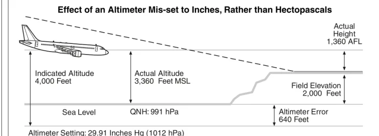
In Figure 3 (page 61), a QNH of 991 hPa was set mistakenly on the altimeter as 29.91 in. Hg (equivalent to 1012 hPa), resulting in the true altitude being 640 feet lower than indicated.
Setting the Altimeter
To help prevent errors associated with different units of measurement or with unusual values (low or high), the following SOPs should be used when broadcasting (ATIS or controllers) or reading back (pilots) an altimeter setting:
• All digits, as well as the unit of measurement (e.g., inches
or hectopascals), should be announced.
A transmission such as “altimeter setting six seven” can be interpreted as 28.67 in. Hg, 29.67 in. Hg, 30.67 in. Hg or 967 hPa.
Effect of a One-inch-high Altimeter Setting
Sea Level Indicated Altitude 4,000 Feet Field Elevation 2,000 Feet Actual Height 1,000 AFL
Altimeter Setting: 29.XX Inches Hg
QNH: 28.XX Inches Hg Actual Altitude 3,000 Feet MSL
Altimeter Error 1,000 Feet
AFL = Above field level MSL = Mean sea level Hg = Mercury
QNH = Altimeter setting that causes altimeter to indicate height above mean sea level (thus, field elevation at touchdown) Source: Flight Safety Foundation Approach-and-landing Accident Reduction (ALAR) Task Force
Figure 1
Effect of a One-inch-low Altimeter Setting
AFL = Above field level MSL = Mean sea level Hg = Mercury
QNH = Altimeter setting that causes altimeter to indicate height above mean sea level (thus, field elevation at touchdown) Source: Flight Safety Foundation Approach-and-landing Accident Reduction (ALAR) Task Force
Figure 2
Sea Level Indicated Altitude 4,000 Feet Field Elevation 2,000 Feet Actual Height 3,000 AFLAltimeter Setting: 29.XX Inches Hg
QNH: 30.XX Inches Hg Actual Altitude 5,000 Feet MSL
Altimeter Error 1,000 Feet
Stating the complete altimeter setting prevents confusion and allows detection and correction of a previous error. • When using in. Hg, “low” should precede an altimeter setting of 28.XX in. Hg and “high” should precede an altimeter setting of 30.XX in. Hg.
An incorrect altimeter setting often is the result of one or more of the following factors:
• High workload;
• A deviation from defined task-sharing; • An interruption/distraction;
• Inadequate cross-checking by flight crewmembers; or, • Confusion about units of measurement.
Adherence to the defined task-sharing (for normal conditions or abnormal conditions) and normal checklists are effective defenses to help prevent altimeter-setting errors.
Metric Altimeter
Metric altitudes in certain countries (e.g., the Commonwealth of Independent States and the People’s Republic of China) also require SOPs for the use of metric altimeters (or conversion tables).
Crossing the Transition Altitude/Flight Level
The transition altitude/flight level can be either:
• Fixed for the whole country (e.g., FL 180 in the United States);
• Fixed for a given airport (as indicated on the approach chart); or,
• Variable, depending on QNH (as indicated in the ATIS broadcast).
Depending on the airline’s/flight crew’s usual area of operation, changing from a fixed transition altitude/flight level to variable transition altitudes/flight levels may result in a premature resetting or a late resetting of the altimeter.
An altitude constraint (expressed in altitude or flight level) also may delay or advance the setting of the standard altimeter setting (1013.2 hPa or 29.92 in. Hg), possibly resulting in crew confusion.
Altimeter References
The barometric-altimeter reference (“bug”) and the radio-altimeter decision height (RA DH) bug must be set according to the aircraft manufacturer’s SOPs or the company’s SOPs. Table 1 (page 62) shows some examples.
For all approaches, except Category (CAT) I instrument landing system (ILS) approaches with RA DH, CAT II ILS approaches and CAT III ILS approaches, the standard call “minimum” will be based on the barometric-altimeter bug set at the minimum descent altitude/height [MDA(H)] or decision altitude/height [DA(H)].
Radio-altimeter standard calls can be either:
• Announced by the PNF (or the flight engineer); or, • Generated automatically by a synthesized voice.
Effect of an Altimeter Mis-set to Inches, Rather than Hectopascals
Sea Level Indicated Altitude 4,000 Feet Field Elevation 2,000 Feet Actual Height 1,360 AFL
Altimeter Setting: 29.91 Inches Hg (1012 hPa) QNH: 991 hPa
Actual Altitude 3,360 Feet MSL
Altimeter Error 640 Feet
AFL = Above field level MSL = Mean sea level Hg = Mercury hPa = Hectopascals
QNH = Altimeter setting that causes altimeter to indicate height above mean sea level (thus, field elevation at touchdown) Source: Flight Safety Foundation Approach-and-landing Accident Reduction (ALAR) Task Force
Standard calls are tailored to the company SOPs and to the type of approach.
To enhance the flight crew’s awareness of terrain, the standard call “radio altimeter alive” should be announced by the first crewmember observing radio-altimeter activation at 2,500 feet above ground level (AGL).
The radio altimeter then should be included in the instrument scan for the remainder of the approach.
The radio altimeter indicates the aircraft’s height above the ground, not the aircraft’s height above airport elevation. The radar altimeter does not indicate height above trees or towers. Nevertheless, unless the airport has high close-in terrain, the radio-altimeter indication should reasonably agree with the height above airport elevation (obtained by direct reading of the altimeter if using QFE or by computation if using QNH). Radio-altimeter indications below the following obstacle-clearance values, should be cause for alarm:
• Initial approach, 1,000 feet;
• Intermediate approach (or minimum radar vectoring altitude), 500 feet; and,
• Final approach (nonprecision approach), 250 feet.
Low Outside Air Temperature (OAT)
In a standard atmosphere, the indicated QNH altitude is the true altitude.
Whenever the temperature deviates significantly from the standard temperature, the indicated altitude deviates from the true altitude, as follows:
• At extremely high temperatures, the true altitude is
higher than the indicated altitude; and,
• At extremely low temperatures, the true altitude is lower
than the indicated altitude, resulting in reduced terrain clearance.
Flying into an area of low temperatures has the same effect as flying into a low-pressure area; the aircraft is lower than the altimeter indicates.
The International Civil Aviation Organization (ICAO) publishes altitude corrections (based on the airport surface temperature and the height above the elevation of the altimeter-setting source) to be made to the published minimum safe altitudes.3
For example, Figure 4 (page 63) shows that when conducting an ILS approach with a published minimum glideslope intercept altitude of 2,000 feet and an OAT of -40 degrees Celsius (-40 degrees Fahrenheit), the minimum glideslope intercept altitude should be increased by 440 feet.
The pilot is responsible for conducting this correction, except when under radar control in a radar-vectoring area (because the controller is responsible normally for terrain clearance, including accounting for the cold temperature correction).
Nevertheless, the pilot should confirm this responsibility with the air traffic services of the country of operation.
Flight crews must apply the ICAO corrections for low temperatures to the following published altitudes:
• Minimum en route altitude (MEA) and minimum safe altitude (MSA);
• Transition route altitude;
• Procedure turn altitude (as applicable); • Final approach fix (FAF) altitude;
• Step-down altitude(s) and MDA(H) during a nonprecision approach;
• Outer marker (OM) crossing altitude during an ILS approach; and,
Table 1
Barometric-altimeter and
Radio-altimeter Reference Settings
Barometric Radio Approach Altimeter Altimeter
Visual MDA(H)/DA(H) of 200 feet* instrument approach
or 200 feet above airport elevation
Nonprecision MDA/(H) 200 feet*
ILS CAT I DA(H) 200 feet*
no RA
ILS CAT I DA(H) RA DH
with RA
ILS CAT II DA(H) RA DH
ILS CAT III DA(H) RA DH
with DH
ILS CAT III TDZE Alert height
with no DH
MDA(H) = Minimum descent altitude/height DA(H) = Decision altitude/height ILS = Instrument landing system CAT = Category
RA DH = Radio altimeter decision height TDZE = Touchdown zone elevation
* The RA DH should be set (e.g., at 200 feet) for terrain-awareness purposes. The use of the radio altimeter should be discussed during the approach briefing.
Note: For all approaches, except CAT II and CAT III ILS approaches, the approach “minimum” call will be based on the barometric-altimeter bug set at MDA(H) or DA(H).
Source: Flight Safety Foundation Approach-and-landing Accident Reduction (ALAR) Task Force
• Waypoint crossing altitudes during a global positioning system (GPS) approach flown with barometric vertical navigation.
ICAO does not provide altitude corrections for extremely high temperatures; however, the temperature effect on true altitude must not be ignored when planning for a constant-angle nonprecision approach (CANPA) (i.e., to maintain the required flight path/vertical speed).
Summary
Altimeter-setting errors result in insufficient vertical-position awareness. The following minimize the potential for altimeter-setting errors and foster optimum use of the barometric-altimeter bug and RA DH bug:
• Awareness of altimeter-setting changes demanded by prevailing weather conditions (extreme cold fronts, extreme warm fronts, steep frontal surfaces, semi-permanent low pressure areas or seasonal low pressure areas); • Awareness of the unit of measurement for setting the
altimeter at the destination airport;
• Awareness of the anticipated altimeter setting (based on aviation routine weather reports [METARs] and ATIS broadcasts);
• PF-PNF cross-checking; and, • Adherence to SOPs for:
– Resetting altimeters at the transition altitude/flight level;
– Using the standby altimeter to cross-check the primary altimeters;
– Altitude calls;
– Radio-altimeter calls; and,
– Setting the barometric-altimeter bug and RA DH bug. The following FSF ALAR Briefing Notes provide information to supplement this discussion
• 1.1 — Operating Philosophy;
• 2.3 — Pilot-Controller Communication;
• 2.4 — Interruptions/Distractions; and,
• 3.2 — Altitude Deviations.♦
References
1. The Flight Safety Foundation Approach-and-landing Accident Reduction (ALAR) Task Force defines causal factor as “an event or item judged to be directly instrumental in the causal chain of events leading to the accident [or incident].” Each accident and incident in the study sample involved several causal factors.
2. Flight Safety Foundation. “Killers in Aviation: FSF Task Force Presents Facts About Approach-and-landing and Controlled-flight-into-terrain Accidents.” Flight Safety Digest Volume 17 (November–December 1998) and Volume 18 (January–February 1999): 1–121. The facts presented by the FSF ALAR Task Force were based on
Effects of Temperature on True Altitude
OAT = Outside air temperature
Source: Flight Safety Foundation Approach-and-landing Accident Reduction (ALAR) Task Force
Figure 4
Given Atmospheric Pressure(Pressure Altitude) True Altitude Low OAT High OAT Indicated Altitude 2,000 Feet 3,000 Feet 2,000 Feet 1,000 Feet Standard OAT 1,560 Feet −440 Feet
analyses of 287 fatal approach-and-landing accidents (ALAs) that occurred in 1980 through 1996 involving turbine aircraft weighing more than 12,500 pounds/5,700 kilograms, detailed studies of 76 ALAs and serious incidents in 1984 through 1997 and audits of about 3,300 flights. 3. International Civil Aviation Organization. Procedures for
Air Navigation Services. Aircraft Operations. Volume I,
Flight Procedures. Part III, Approach Procedures. Fourth edition - 1993. Reprinted May 2000, incorporating Amendments 1–10.
Related Reading from FSF Publications
Flight Safety Foundation (FSF) Editorial Staff. “Boeing 737 Pilot Flying Selects Incorrect Altitude in Holding Pattern, Causes Dangerous Loss of Separation with MD-81. Accident Prevention Volume 55 (April 1998).
FSF Editorial Staff. “During Nonprecision Approach at Night, MD-83 Descends Below Minimum Descent Altitude and Contacts Trees, Resulting in Engine Flame-out and Touchdown Short of Runway.” Accident Prevention Volume 54 (April 1997). FSF Editorial Staff. “Learjet MEDEVAC Flight Ends in Controlled-flight-into-terrain (CFIT) Accident.” Accident Prevention Volume 54 (January 1997).
FSF Editorial Staff. “Different Altimeter Displays and Crew Fatigue Likely Contributed to Canadian Controlled-flight-into-terrain Accident.” Accident Prevention Volume 52 (December 1995).
Lawton, Russell. “DC-10 Destroyed, No Fatalities, After Aircraft Veers Off Runway During Landing.” Accident Prevention Volume 51 (May 1994).
Regulatory Resources
International Civil Aviation Organization (ICAO). International Standards and Recommended Practices, Annex 3 to the Convention of International Civil Aviation, Meteorological Service for International Air Navigation. Chapter 4, “Meteorological Observations and Reports.” Thirteenth edition – July 1998. ICAO. International Standards, Annex 5to the Convention of International Civil Aviation, Units of Measurement to be Used in Air and Ground Operations. Chapter 3, “Standard Application of Units of Measurement,” Table 3-4, “Standard application of specific units of measurement.” Fourth edition – July 1979. ICAO. International Standards and Recommended Practices, Annex 6 to the Convention of International Civil Aviation, Operation of Aircraft. Part I, International Commercial Air Transport - Aeroplanes. Chapter 6, “Aeroplane Instruments, Equipment and Flight Documents,” 6.9.1. Appendix 2, “Contents of an Operations Manual,” 5.13. Seventh edition – July 1998, incorporating Amendments 1–25.
ICAO. Procedures for Air Navigation Services. Rules of the Air and Air Traffic Services. Thirteenth edition – 1996, incorporating Amendments 1–3.
ICAO. Preparation of an Operations Manual. Second edition – 1997.
ICAO. Manual of Radiotelephony. Second edition – 1990. ICAO. Human Factors Training Manual. First edition – 1998, incorporating Circular 216.
ICAO. Circular 241, Human Factors Digest No. 8, “Human Factors in Air Traffic Control.” 1993.
The Flight Safety Foundation (FSF) Approach-and-landing Accident Reduction (ALAR) Task Force has produced this briefing note to help prevent ALAs, including those involving controlled flight into terrain. The briefing note is based on the task force’s data-driven conclusions and recommendations, as well as data from the U.S. Commercial Aviation Safety Team (CAST) Joint Safety Analysis Team (JSAT) and the European Joint Aviation Authorities Safety Strategy Initiative (JSSI).
The briefing note has been prepared primarily for operators and pilots of turbine-powered airplanes with underwing-mounted engines (but can be adapted for fuselage-mounted turbine engines, turboprop-powered aircraft and piston-turboprop-powered aircraft) and with the following: • Glass flight deck (i.e., an electronic flight instrument system
with a primary flight display and a navigation display); • Integrated autopilot, flight director and autothrottle systems;
Notice
• Flight management system; • Automatic ground spoilers; • Autobrakes;
• Thrust reversers;
• Manufacturers’/operators’ standard operating procedures; and, • Two-person flight crew.
This briefing note is one of 34 briefing notes that comprise a fundamental part of the FSF ALAR Tool Kit, which includes a variety of other safety products that have been developed to help prevent ALAs.
This information is not intended to supersede operators’ or manufacturers’ policies, practices or requirements, and is not intended to supersede government regulations.
Copyright © 2000 Flight Safety Foundation Suite 300, 601 Madison Street, Alexandria, VA 22314 U.S.
Telephone +1 (703) 739-6700, Fax: +1 (703) 739-6708 www.flightsafety.org
In the interest of aviation safety, this publication may be reproduced, in whole or in part, in all media, but may not be offered for sale or used commercially without the express written permission of Flight Safety Foundation’s director of publications. All uses must credit Flight Safety Foundation.