TECHNICALUNIVERSITY OF CLUJ-NAPOCA
ACTA TECHNICA NAPOCENSIS
Series: Applied Mathematics, Mechanics, and Engineering
Vol. 63, Issue I, March, 2020
PARAMETRIC ANALYSIS OF VIBRATING EQUIPMENT FOR THE
INSERTION OF PILES INTO THE GROUND
Oana TONCIU
SUMMARY. The paper presents the dynamic model for vibration insertion equipment for piles and grooved piles. For this, several constructive solutions were analysed, so that the dynamic model chosen is representative. As a consequence, the paper comprises the dynamic analysis of the system response to the action of the perturbing force generated by an inertial vibrator with four synchronized eccentric masses in-phase, to ensure a vertical unidirectional dynamic action. Finally, the paper presents the curves of variation of the amplitudes of the masses in the vibrational movement, with the optimal functional regimes.
The dynamic model in the paper was used to analyse the dynamic response for the functional optimization of the vibrodrivers on the sites located along the Danube for the consolidation of the navigation channel bed.
Keywords: dynamic model, vibrations, piles, grooved piles.
1. INTRODUCTION
The vibrating equipment for the insertion of the piles into the ground are the unidirectional vibrodrivers mounted on a support plate, which are fixed on the upper end of the driving element (grooved piles, piles). Vibrodrivers are vibrating action machines intended for the grounding of some construction elements (in the case of execution and consolidation of foundation works), including grooved piles and piles, in non-cohesive, water-soaked, low and medium compaction soils, as well as in some soft cohesive soils (weak plastic clays).
Depending on the characteristics of the land, the dynamic assessment of the driving element (the working element) is performed so that the amplitude and frequency of the technological vibrations represent certain characteristics at a minimum predictable level leading to the correct execution of the pile insertion in the ground process. For this reason, it is necessary that when changing the site, the characteristics of the land shall be assessed so
that the necessary adjustment of the vibrating
equipment can be made in order to achieve the necessary technological vibrations.
2. FUNCTIONAL AND
CONSTRUCTIVE SCHEMATIZATION
The vibrodrivers have in their composition inertial vibration generators fixed rigidly at the end of the working element (grooved pile or pile). The most commonly used construction solutions classify the vibrating equipment for inserting piles into the ground as follows:
a) Vibrodrivers with rigid fixation of the
driving motor in relation to the vibration generator (fig. 1 a where: 1 – driving motor; 2 – vibration generator; 3 – support platform; 4 – pile fixing device)
b) Vibrodrivers with elastic support of the
Fig. 1. Vibrodrivers for piles
The vibrodrivers with rigid fixing of the driving motor to the vibration generator have the advantage of a simple construction, but their use implies the following disadvantages:
- increasing the vibrator weight, by
adding additional weights, reduces the amplitude of the vibrations and implicitly the insertion speed of the pile;
- reducing the reliability of electric
motors due to the fact that the motor is subjected to the same vibrations as the driving element;
- the need to ensure the protection of the
equipment carrying the vibrodriver against the transmission of the vibrations to it.
The second constructive type of vibrodriver (fig. 1 b) is composed of two parts with elastic connection through coil springs system, as follows:
- the vibrating part comprising the
vibrator 1 and its gripping device to the working element 2;
- the upper part consisting of the
insulation support plate 3 and the driving motor 4, the same being
dynamically isolated from the elastic connection formed by the coil springs. The constructive solution with elastic supported motor allows additional pressing of the driving element, thus leading to a combined vibration-pressing effect with good results when introducing the piles in non-cohesive and poorly cohesive soils.
The elastic constant of the springs is chosen so that the pulse of the plate 3 is lower than the one of the vibrator, in which case the springs play the role of dynamic isolator.
From the comparative analysis, it results that the amplitude of the vibrations and the loading pressure cannot be varied and separated, because the two sizes are in an inverse proportional ratio.
3. ANALYSIS OF THE DYNAMIC
RESPONSE
hereafter present the dynamic modelling for the vibrating equipment with elastic supported driving motor.
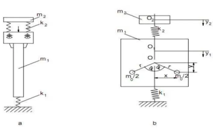
The model used for modelling most of the vibrating equipment for driving the grooved
piles and piles intothe ground is the one of the
linear vibrating system with 2 concentrated masses as in figure 2 a.
For the study of this model, the dynamic calculation scheme represented in fig. 2 b has
been adopted.
Fig. 2. Dynamic calculation model and scheme
The defining parameters for the dynamic model in figure 2 are as follows:
m1 is the total mass of the vibrator with the
gripping system and the working element;
m2 – the mass of the driving motor together
with the setting platform;
k2 – the stiffness coefficient of the elastic
elements on which the motor platform rests;
k1 – the stiffness coefficient of the soil;
m0 – the total mass of the eccentric elements of
inertial imbalance in the vibrator component; r – the eccentricity of the imbalance elements.
The position of the masses m1, m2 and m0 is
given by the instantaneous coordinates y1, y2
and
ϕ
.The differential equations of the movement of the mechanical system are of the following form:
+ ⋅ − −
+ + − = 0
− − = 0− +
+ + = where:
J0 is the moment of total inertia of the eccentric
imbalance masses reduced to the rotation axis of the vibrator motor wheel;
M – the moment of the driver torque
corresponding to the vibrator motor shaft;
ϕ
- the position angle of the eccentric masses.For the stabilized operating regime, that is t
⋅
=ω
ϕ ; = and = 0, the differential
equations of movement shall have the following form:
+ + + −
=
− − = 0
− +
=
(4) (5) (6)
By solving the above system, it results two own forms of vibration with the own pulsations p1 and p2 given by the following relation:
The dislocations y1, y2 are of harmonic form
with the amplitudes:
D k r m A D m k r m A 2 2 0 2 2 2 2 2 0 1 ) ( ω ω ω = − = where
(
)
[
]
(
)
22 2 2 2 2 2 0 1
1 m m ω k mω mkω
k
D= − + − − (10)
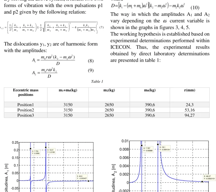
The way in which the amplitudes A1 and A2
vary depending on the ω current variable is
shown in the graphs in figures 3, 4, 5.
The working hypothesis is established based on experimental determinations performed within ICECON. Thus, the experimental results obtained by direct laboratory determinations are presented in table 1:
Table 1
Eccentric mass
positions m1+m0(kg) m2(kg) m0(kg) r(mm)
Position1 3150 2650 390,6 24,3
Position2 3150 2650 390,6 53,16
Position3 3150 2650 390,6 94,27
Fig.3. The variation of amplitudes A1 and A2 for position 1 of the eccentric masses
0 10 20 30 40 50
-0.25 -0.2 -0.15 -0.1 -0.05 0 0.05 0.1 0.15 0.2 0.25 X: 46.8 Y: -0.003437
ω [rad/s]
A m p lit u d in e a , A1 [ m ] X: 18.01 Y: 0.2166 X: 7.753 Y: 0.2085
0 10 20 30 40 50
-0.01 -0.008 -0.006 -0.004 -0.002 0 0.002 0.004 0.006 0.008 0.01 X: 46.07 Y: 0.0002151
ω [rad/s]
A m p lit u d in e a , A 2 [ m ] X: 18.1 Y: 0.009124 X: 7.767 Y: 0.00888 (8) (9)
( ) (7)
4 2 1 2 1 2 0 1 2 1 2 0 1 2 1 2 2 0 1 2 1 2 2 2 ,
1
Fig.4. The variation of amplitudes A1 and A2 for position 2 of the eccentric masses
Fig.5. The variation of amplitudes A1 and A2 for position 3 of the eccentric masses
4. CONCLUSIONS
Following the dynamic analysis of the model with two degrees of freedom that schematizes the behaviour of the vibrating equipment for inserting piles into the ground, the following conclusions are drawn:
1) the amplitudes of the two masses are represented
in the graphs of figures 3, 4 and 5 for three positions of the eccentric masses.
2) the amplitude in the resonance points (p1
respectively p2) tends towards very large values,
asymptotically. These areas should be avoided so that the system works in a stable regime.
0 10 20 30 40 50
-0.1 -0.08 -0.06 -0.04 -0.02 0 0.02 0.04 0.06 0.08 0.1
X: 46.59 Y: -0.007528
ω [rad/s]
A
m
p
lit
u
d
in
e
a
,
A1
[
m
]
X: 18.1 Y: 0.08921 X: 7.698
Y: 0.08969
0 10 20 30 40 50
-0.2 -0.15 -0.1 -0.05 0 0.05 0.1 0.15 0.2
X: 18.1 Y: 0.1686
ω [rad/s]
A
m
p
lit
u
d
in
e
a
,
A 1
[
m
]
X: 7.702 Y: 0.1689
X: 45.75 Y: -0.01342
0 10 20 30 40 50
-0.04 -0.03 -0.02 -0.01 0 0.01 0.02 0.03 0.04
X: 45.84 Y: 0.0008448
ω [rad/s]
A
m
p
lit
u
d
in
e
a
,
A2
[
m
]
X: 18.1 Y: 0.03552 X: 7.767
Y: 0.03552
0 10 20 30 40 50
-0.05 -0.04 -0.03 -0.02 -0.01 0 0.01 0.02 0.03 0.04 0.05
X: 45.95 Y: 0.0004736
ω [rad/s]
A
m
p
lit
u
d
in
e
a
,
A2
[
m
]
X: 18.1 Y: 0.04542 X: 7.518
3) for the amplitudes A1 and A2 it is found that in steady regime to post-resonance, the amplitude
A1 for the three analysed situations has a
constant and stable value, so that the assessment of the technological process can be carried out
effectively. The amplitude A2 (the one of the
support platform) tends to zero so that the dynamic isolation of the motor can be ensured in a proportion of 95 %.
4) the experimental results obtained within
ICECON confirm that the graphical
representation is correct and significant. It can be considered that the model with two degrees of freedom is plausible, consistent and realistically reflects the dynamic behaviour of the system.
5) compared to the above, the presented dynamic
analysis can be a preliminary basis for assessing the ability of the vibrating insertion equipment for characteristics of the land in a given location, so that the insertion speed and depth set in the process design stage can be reached.
REFERENCES:
[1] Drucker, D., C., Prager, W., Soil mechanics and plastic analysis or limit design, Quart. Applied
Math. Vol. 10 No. 2 pp. 157 – 165, 1952;
[2] Lambe, T. W., Whitman, R. V., Soil mechanics, John
Wiley&Sons, 553 pages, 1969.
[3] Mihăilescu, Șt., Bratu, P., Goran V., Vlădeanu A.,
Masini de constructii[Construction machines] vol.
2 Technical Publishing House, Bucharest, Romania, 1985;
[4] Holtz, R. D., Kovacs, W. D., Sheahan, T.C., An introduction to geotechnical engineering, Prentince
Hall, 2010.
[5] Richart, F.E., Hall, J.R., Woods, R.D., Vibrations of soils and foundations, Newmark, N.M., W.J. Hall,
414 pages, 1970.
[6] Bratu, P. , Vibrațiile sistemelor elastic [Vibrations of Elastic Systems], Technical Publishing House,
Bucharest 2000.
[7] Polidor Bratu, Adriana Stuparu, Sorin Popa, Ovidiu Voicu, Nicolae Iacob, Gianina Spânu “The Dynamic Isolation Performances analysis of the vibrating equipment with elastic links to a fixed fixed base” – ACTA NAPOCENSIS – Applied
Mathematics, mechanics and engineering, vol. 61, no. 1 (2018);
[8] Polidor Bratu “Analysis of the dynamic regime of forced vibrations in the dynamic compacting process with vibrating rollers „ - ACTA
NAPOCENSIS – Applied Mathematics, mechanics and engineering, vol. 61, no. 1 (2018). [9] Dobrescu C. F., Brăguța E. , Optimization of Vibro-Compaction Technological Process Considering Rheological Properties Acoustics and and Vibration of Mechanical Structures AVMS-2017,
Proceedings of the 14 AVMS Conference, Timisoara, Romania, ISBN 978-3-319-69822-9, ISSN 0930-8989.
[10] Dobrescu C. F., Brăguța E., Evaluation of strength and deformation parameters of soil based on laboratory tests, Multi-Conference on
Systems&Structures (SysStruc 17) from Eftimie Murgu University in Resita November 9th-11th, 2017.
[11] Briaud, J-L., Introduction to Soil Moduli,
Geotechnical News, Bitech Publishers Ltd, Richmond, B.C., Canada, 2001
ANALIZA PARAMETRICĂ A ECHIPAMENTELOR VIBRATOARE DE ÎNFIGERE A
PILOȚILOR ÎN PĂMÂNT
REZUMAT. În lucrare se prezintă modelul dinamic pentru echipamentele de înfigere prin vibrare pentru piloţi şi palplanşe. Pentru
aceasta au fost analizate mai multe soluţii constructive, astfel încât modelul dinamic ales să fie reprezentativ. În conseecinţă, lucrarea cuprinde analiza dinamică a răspunsului sistemului la acţiunea forţei perturbatoare generată cu un vibrator inerţial cu patru mase excentrice sincronizate în fază, pentru asigurarea unei acţiuni dinamice unidirecţionale pe verticală. În final se prezintă curbele de variaţie a amplitudinilor maselor în mişcarea vibratorie, cu regimurile optime funcţionale. Modelul dinamic din lucrare a fost utilizat la analiza răspunsului dinamic pentru optimizarea funcțională a vibroînfigătoarelor pe șantierele situate în lungul Dunării pentru consolidarea albiei șenalului navigabil.