doi 10.15802/stp2017/117973 O. S. Danylova, A. S. Shcherbak, А. V. Krasniuk, 2017
UDC 514.182
O. S. DANYLOVA
1*, A. S. SHCHERBAK
2, А. V. KRASNIUK
31*
Dep. «Graphics», Dnipropetrovsk National University of Railway Transport named after Academician
V. Lazaryan, Lazaryan St., 2, Dnipro, Ukraine, 49010, tel. +38 (056) 373 15 59, e-mail [email protected], ORCID 0000-0003-1375-0575
2
Dep. «Graphics», Dnipropetrovsk National University of Railway Transport named after Academician V. Lazaryan, Lazaryan St., 2, Dnipro, Ukraine, 49010, tel. +38 (056) 373 15 59, [email protected], ORCID 0000-0003-1340-0284
3
Dep. «Graphics», Dnipropetrovsk National University of Railway Transport named after Academician
V. Lazaryan, Lazaryan St., 2, Dnipro, Ukraine, 49010, tel. +38 (056) 373 15 59, e-mail [email protected], ORCID 0000-0002-1400-9992
POINTS ON THE SPHERE SURFACE
Purpose. The extensive use of the computer-aided design system (CAD) in education and industry puts forward new demands on the scope, content and quality of up-to-date descriptive geometry course. The purpose of the work is topicality analysis of traditional descriptive geometry methods for 3D modelling and development of methodolo-gical recommendations for its teaching as a subject together with a selected CAD. Methodology. Conclusions about effectiveness and expedience of application of descriptive geometry methods are drawn on the basis of tools analysis and comparison of modern CADs and descriptive geometry for solving problems arising during 3D modelling. Ge-neralization of teaching experience made it possible to give recommendations about optimization of the descriptive geometry course taking into account present-day requirements to professional skills of an engineer.
Findings. CADs tools and descriptive geometry methods are compared by way of specific example to give the an-swer what is more suitable for solving problems arising during 3D modelling. Originality. We presented the me-thodological recommendations about optimization of descriptive geometry teaching together with a selected CAD. We proposed the conception of a modern textbook on descriptive geometry. First of all, the textbook must describe algorithms for solving problems by means of standard CAD tools exactly in 3D, not on the plane. It is desirable to accompany these algorithms by pictorial images in order to have an opportunity to grasp an idea quickly and imple-ment it through methods of direct modeling in CAD application. We also touched practical problems of students’ motivation to ensure high effectiveness of graphical education. Practical value. This paper may be useful mainly for educators in the field of engineering graphics because it raises a vital question ‘Descriptive Geometry versus CAD’ which now has no definite answer. Topicality and teaching approaches of different solution methods of spa-tial problems by means of projections is subject of a dispute, taking into account that CAD tools are continuously updated. This paper by way of specific example shows some advantages and limitations of descriptive geometry and CAD, as well as touches the issues of their efficient joint application for teaching.
Keywords: descriptive geometry; CAD; sphere; teaching methods; motivation
Introduction
The surface of a sphere is considered definite,
if the position of its centre and the radius are
known. The sphere is the surface of revolution.
The sphere is also the surface of a full sphere. In
computer-aided
design
systems,
a
three-dimensional model of a sphere can be constructed
by rotating a semicircle around its diameter, i.e. by
kinematic way of surface formation. In AutoCAD
for construction, there is also a separate command
[9], the initial data for which are the coordinates of
the centre point of the sphere and the size of its
radius – the analytical method.
Purpose
doi 10.15802/stp2017/117973 O. S. Danylova, A. S. Shcherbak, А. V. Krasniuk, 2017
a typical way of determining a surface, although it
can occur when solving practical problems.
Methodology
As sphere is the geometric locus of points in
space equidistant from a point called the sphere
cen-tre, then the solution of this problem consists in
finding a point equidistant from the four given
values [2]. Thus, with 3D modelling, we come
across a separate class of problems, when it is
necessary to go from one set of input data (4 points
on the sphere surface) to the other (sphere centre
and radius). Such problems can be successfully
solved by DG methods, and the construction
algorithms are used in computer simulation.
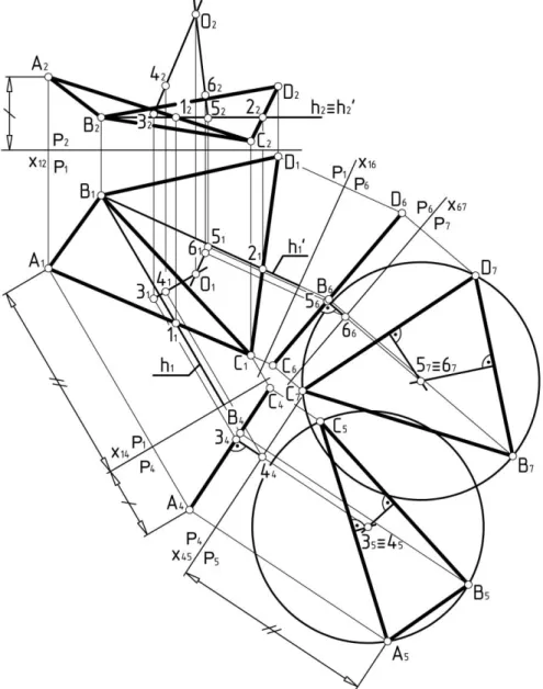
Fig. 1. Construction of sphere centre by 4 points (four replacements of projection planes)
Fig. 1 shows one of the possible graphical
solutions of this problem using DG methods. There
are given four points A, B, C, D in two projections.
The found points O
1and O
2are the desired
projections of the sphere centre. As you know, you
can draw a circle through any three given points.
doi 10.15802/stp2017/117973 O. S. Danylova, A. S. Shcherbak, А. V. Krasniuk, 2017
their centres. The intersection point of the
perpen-diculars will be the sphere centre.
On the plane, by using a double replacement of
the projection planes, we found the natural value of
each of the two planes formed by the given points.
Then we constructed the sphere parallels,
perpen-diculars from their centres, and found the
intersec-tion point of these perpendiculars. From the point of
view of DG, this method of solving the problem on
the plane is not optimal, because there is another
one, which requires fewer graphic. However, this is
a simple and understandable way to solve the
problem straight forward.
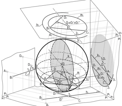
Figures 2 and 3 show the second way of finding
the desired sphere centre. We take any three points
for belonging to a common parallel and find its
centre. Using the fourth point, we construct another
parallel and find the sphere centre. Since any
of the given points can be taken as the fourth one,
there are four possible solutions.
Fig. 2. Construction of sphere centre by 4 points (double replacement of projection planes)
To solve the problem, it is also necessary to
re-place the projection planes twice. We turn the points
C, B and D into a plane, passing through them the
intersecting lines CD and the horizontal h. We find
the natural value of this plane and construct a circle
around the three points C, B, D – projection of the
parallel m
5. Through the fourth point A, the
projec-tion of the second parallel k
5is constructed. On
plane P
5both parallels are projected in the form of
concentric circles, and on P
4in the form of parallel
segments of straight lines. The extreme points of the
projections of parallels 2 and 3 define a circle whose
centre coincides with the sphere centre. Points 2 and
3 must be joined by a straight line segment. From
the middle of this segment, we restore the
perpen-dicular, which will pass through the sphere centre.
doi 10.15802/stp2017/117973 O. S. Danylova, A. S. Shcherbak, А. V. Krasniuk, 2017
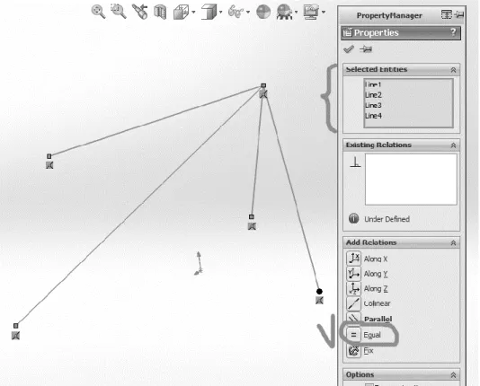
For example, in SolidWorks, to find the sphere
centre in a three-dimensional sketch, you can select
an arbitrary point and connect it to four specified
points with straight line segments. Then you need to
select all the lines and define the geometric
«equality» relationship between them (Figure 4).
The
program
will
automatically
move
an arbitrarily chosen point to such a position that
all segments become the same length, i.e. it will
find the sphere centre – a point equidistant
from the four given values.
Fig. 3. Construction of sphere centre by 4 points (double replacement of projection planes), visual image
Next, we need to construct a plane through the
centre and any two points, construct a semicircle in
this plane and obtain the sphere by the rotation
method.
This method cannot be used in AutoCAD and
KOMPAS-3D.
In
KOMPAS-3D,
parametric
constraints can only be imposed on flat objects
in a sketch, and in AutoCAD such geometric
dependencies cannot be applied to objects lying in
different planes.
Findings
Despite the fact that modern CAD systems are
quite a powerful tool, they are not perfect, i.e. do
not have tools «for all occasions». Moreover, the
effectiveness of their use directly depends on the
user's skills, including his geometrical-graphic
training. The study of descriptive geometry is one
of the most important stages of such training.
In addition to its main purpose of developing
spatial thinking, descriptive geometry studies
methods of solving the applied tasks. Many of
these tasks can be solved by CAD, but one of the
areas remaining relevant in DG so far is the
solution of tasks that require a transition from one
set of initial geometric data to another set of such
data needed for modelling [17].
Originality and practical value
doi 10.15802/stp2017/117973 O. S. Danylova, A. S. Shcherbak, А. V. Krasniuk, 2017
algorithms for task solving using the typical CAD
tools exactly in 3D, and not on a plane. It is
desirable to accompany these algorithms by
pictorial images in order to have an opportunity to
grasp an idea quickly and implement it in 3D.
Complex constructions on the plane go to the
background.
Fig. 4. Specifying the geometric «equality» relationship for straight line segments in SolidWorks
Conclusions
The solution of the problem in the
three-dimensional space of the program is a natural
process for a man. DG methods for solving spatial
problems on a plane were developed when there
was simply no other way to obtain a result. These
methods are beautiful and elegant and often startle
the imagination, but are they needed now, when
the result can be achieved by pressing just a few
buttons? Of course, we cannot and should not
completely abandon the methods of classical DG:
there are situations when they are still necessary.
But the number of such tasks is getting smaller
every year. Modern DG course should, first of all,
include algorithms based on methods of direct
modelling in 3D space, avoiding projection
trans-formations.
As it is known, DG is considered by most
students as a complex subject, for the study of
which one needs certain motivation. Many students
having acquainted with 3D modelling programs do
not understand what the meaning of studying DG
is, «if everything can be built on a computer».
Therefore, methodically it makes sense to divide
a joint study of DG and engineering computer
graphics into two stages.
The first stage: study of the basic capabilities of
CAD. At this stage the proposed tasks do not
require involvement of DG and are designed to
teach a user to apply the main CAD tools. The task
of this stage is to give the student a powerful tool
and to teach him how to use it. The user should
receive positive emotions from the fact that he can
build 3D models and receive drawings using
com-puter programs. It is very important that at this
stage the student learns to achieve a positive result
on his own.
doi 10.15802/stp2017/117973 O. S. Danylova, A. S. Shcherbak, А. V. Krasniuk, 2017
in the relevant CAD. The tasks should contain
some of the tasks of DG, which is skillfully woven
into the existing geometry. Herewith by the total
volume of work and visually the models at this
stage can be simpler than the previous ones.
A situation is created when a user who knows how
to use CAD cannot build a «simpler geometry»
[11]. It is necessary to draw from the user an
emo-tional state of excitement, which is characterized
by a very strong interest in what is happening and
a persistent desire to continue. It is very important
to give the student time to think independently
before explaining the solution. Perhaps this is the
most important point of learning. It makes sense to
give clues that will indicate the desired direction of
the solution search. The task of the teacher is to
show the student DG place and possibilities for
solving the problems that arise during 3D
modelling.
LIST OF REFERENCE LINKS
1. Иванов, Г. С. Перспективы начертательной геометрии как учебной дисциплины / Г. С. Иванов //
Гео-метрия и графика – 2013. – Т. 1, вып. 1 – С. 26–28. doi: 10.12737/467.
2. Лосев, Н. В. 200 олимпиадных задач по начертательной геометрии : практ. пособие / Н. В. Лосев. – Москва : Высш. шк., 1992. – 144 с.
3. Междисциплинарные связи начертательной геометрии и смежных разделов высшей математики /
И. М. Дмитриева, Г. С. Иванов, В. И. Серегин, К. А. Муравьев // Геометрия и графика. – 2013. – Т. 1, вып. 3. – С. 8–12. doi: 10.12737/2124.
4. Сальков, Н. А. Геометрическое моделирование и начертательная геометрия / Н. А. Сальков //
Геомет-рия и графика. – 2016. – Т. 4, вып. 4. – С. 31–40. doi: 10.12737/22841.
5. Сальков, Н. А. Место начертательной геометрии в системе геометрического образования технических
вузов / Н. А. Сальков // Геометрия и графика. – 2016. – Т. 4, вып. 3. – С. 53–61. doi: 10.12737/21534.
6. Сальков, Н. А. Начертательная геометрия — база для компьютерной графики / Н. А. Сальков //
Гео-метрия и графика. – 2016. – Т. 4, вып. 2. – С. 37–47. doi: 10.12737/19832.
7. Хейфец, А. Л. Начертательная геометрия как «бег в мешках» / А. Л. Хейфец // Проблемы качества
гра-фической подготовки студентов в техническом ВУЗе: традиции и инновации : материалы V Междунар. науч.-практ. интернет-конф. – Пермь, 2015. – Т. 1. – С. 298–325.
8. Хейфец, А. Л. Реорганизация курса начертательной геометрии как актуальная задача развития кафедр
графики / А. Л. Хейфец // Геометрия и графика. – 2013. – Т. 1, вып. 2. – С. 21–23. doi: 10.12737/781.
9. Autodesk AutoCAD Help [Electronic resource]. – Available at:
http://help.autodesk.com/view/ACD/2016/ENU/. – Title from screen. – Accessed : 02.10.2017.
10. Bokan, N. Computer-Aided Teaching of Descriptive Geometry / N. Bokan, M. Ljucovic, S. Vukmirovic // Journal for Geometry and Graphics. – 2009. – Vol. 13, No. 2. – P. 221–229.
11. Danilov, E. Descriptive Geometry for CAD Users: Ribs Construction / E. Danilov // Journal for Geometry and
Graphics. – 2014. – Vol. 18, No. 1. – P. 115–124.
12. SolidWorks Web Help[Electronic resource]. – Available at: http://help.solidworks.com/. – Title from screen.
–Accessed : 02.10.2017.
13. Suzuki, K. Application of descriptive geometry procedures in solving spatial problems with feature and
parametric modelling 3D-CAD / K. Suzuki, H-P. Schroecker // Proc. of the 13th ICGG. – Dresden, Germany,
2008. – Vol. II. – P. 1–8.
14. Suzuki, K. Introduction to 3D-CAD/CG – Learning geometry and graphics through Inventor and 3ds Max. –
2nded. [in Japanese] / K. Suzuki, Y. Yokoyama, T. Kanai. – Tokyo, Japan, 2012.
15. Suzuki, K. Significance of traditional geometry in teaching and learning graphic science / K. Suzuki // CADDM: computer aided drafting, design and manufacturing. – 2013. – Vol. 23/3. – P. 49–55.
16. Suzuki, K. Traditional Descriptive Geometry Education in the 3D-CAD/CG Era / K. Suzuki // Journal for Geometry and Graphics. – 2014. – Vol. 18, No. 2. – P. 249–258.
17. Zsombor-Murray, P. A Cylinder of Revolution on Five Points / P. Zsombor-Murray, S. El Fashny // Journal
doi 10.15802/stp2017/117973 O. S. Danylova, A. S. Shcherbak, А. V. Krasniuk, 2017
О. С. ДАНИЛОВА
1*, А. С. ЩЕРБАК
2, А. В. КРАСНЮК
31*Каф. «Графіка», Дніпропетровський національний університет залізничного транспорту імені академіка В. Лазаряна, вул. Лазаряна, 2, Дніпро, Україна, 49010, тел. +38 (056) 373 15 59, ел. пошта [email protected],
ORCID 0000-0003-1375-0575
2Каф. «Графіка», Дніпропетровський національний університет залізничного транспорту імені академіка В. Лазаряна, вул. Лазаряна, 2, Дніпро, Україна, 49010, тел. +38 (056) 373 15 59, ел. пошта [email protected], ORCID 0000-0003-1340-0284 3Каф. «Графіка», Дніпропетровський національний університет залізничного транспорту імені академіка В. Лазаряна, вул. Лазаряна, 2, Дніпро, Україна, 49010, тел. +38 (056) 373 15 59, ел. пошта [email protected],
ORCID 0000-0002-1400-9992
ТОЧКИ НА ПОВЕРХНІ СФЕРИ
Мета. Широке застосування системи автоматизованого проектування (САПР) в навчальному процесі та на виробництві висуває нові вимоги до об’єму, змісту й якості викладання сучасного курсу нарисної геомет-рії. Метою роботи є аналіз актуальності методів класичної нарисної геометрії для задач геометричного мо-делювання та розробка методичних рекомендацій її викладання як навчальної дисципліни спільно з обраною
САПР. Методика. Висновки про ефективність та доцільність використання методів нарисної геометрії
зроблені на основі аналізу й порівняння можливостей сучасних САПР та нарисної геометрії для вирішення питань, які виникають у процесі тривимірного моделювання. Узагальнення досвіду викладання графічних дисциплін дозволило дати рекомендації щодо оптимізації викладання курсу нарисної геометрії з
урахуван-ням сучасних вимог до кваліфікації інженера. Результати. На конкретному прикладі проведено порівняння
можливостей САПР та методів нарисної геометрії для вирішення проблем, які виникають при
геометрично-му моделюванні. Наукова новизна. Надані методичні рекомендації відносно організації та оптимізації
ви-кладання курсу нарисної геометрії спільно з обраною САПР. Запропонована концепція сучасного підручни-ка з нарисної геометрії, який, перш за все, повинен давати алгоритми для вирішення задач типовими інстру-ментами САПР саме в 3D, а не на площині. Бажано, щоб ці алгоритми супроводжувалися наочними зобра-женнями, які б дозволяли швидко вловити ідею та реалізувати її методами прямого моделювання у середовищі програми тривимірного моделювання. Розглянуті практичні питання мотивації студентів при
вивченні нарисної геометрії. Практична значимість. Дана робота, насамперед, буде цікава викладачам
графічних дисциплін, так як порушує актуальне питання «нарисна геометрія проти САПР», на яке зараз не-має однозначної відповіді. Актуальність та спосіб викладання тих або інших методів вирішення просторо-вих задач за допомогою проекції на площині, при постійно зростаючих можливостях прямого 3D моделю-вання засобами САПР, є предметом обговорення та суперечок. Дана робота на прикладі демонструє можли-вості й обмеження нарисної геометрії та САПР, а також торкається питань ефективності їх спільного викла-дання.
Ключові слова: нарисна геометрія; САПР; сфера; методика викладання; мотивація
О. С. ДАНИЛОВА
1*, А. С. ЩЕРБАК
2, А. В. КРАСНЮК
31*Каф. «Графика», Днепропетровский национальный университет железнодорожного транспорта имени академика В. Лазаряна, ул. Лазаряна, 2, Днипро, Украина, 49010, тел. +38 (056) 373 15 59, эл. почта [email protected], ORCID 0000-0003-1375-0575
2Каф. «Графика», Днепропетровский национальный университет железнодорожного транспорта имени академика В. Лазаряна, ул. Лазаряна, 2, Днипро, Украина, 49010, тел. +38 (056) 373 15 59, эл. почта [email protected],
ORCID 0000-0003-1340-0284
3Каф. «Графика», Днепропетровский национальный университет железнодорожного транспорта имени академика В. Лазаряна, ул. Лазаряна, 2, Днипро, Украина, 49010, тел. +38 (056) 373 15 59, эл. почта [email protected], ORCID 0000-0002-1400-9992
ТОЧКИ НА ПОВЕРХНОСТИ СФЕРЫ
doi 10.15802/stp2017/117973 O. S. Danylova, A. S. Shcherbak, А. V. Krasniuk, 2017
рекомендаций её преподавания как учебной дисциплины совместно с выбранной САПР. Методика. Выводы
об эффективности и целесообразности применения методов начертательной геометрии сделаны на основе анализа, сравнения возможностей современных САПР и начертательной геометрии для решения вопросов, возникающих в процессе трехмерного моделирования. Обобщение опыта преподавания графических дисци-плин позволило дать рекомендации по оптимизации преподавания курса начертательной геометрии с
уче-том современных требований к квалификации инженера. Результаты. На конкретном примере проведено
сравнение возможностей САПР и методов начертательной геометрии для решения проблем, возникающих
при геометрическом моделировании. Научная новизна. Даны методические рекомендации относительно
организации и оптимизации преподавания курса начертательной геометрии совместно с выбранной САПР. Предложена концепция современного учебника по начертательной геометрии, который, прежде всего, дол-жен давать алгоритмы для решения задачи типовыми инструментами САПР именно в 3D, а не на плоскости. Желательно, чтобы эти алгоритмы сопровождались наглядными изображениями, позволяющими быстро уловить идею и реализовать её методами прямого моделирования в среде программы трехмерного модели-рования. Затронуты практические вопросы мотивации студентов при изучении начертательной геометрии.
Практическая значимость. Данная работа, прежде всего, будет интересна преподавателям графических дисциплин, т. к. поднимает актуальный вопрос «начертательная геометрия против САПР», на который сей-час нет однозначного ответа. Актуальность и способ преподавания тех или иных методов решения про-странственных задач с помощью проекций на плоскости, при постоянно растущих возможностях прямого 3D моделирования средствами САПР, является предметом обсуждения и споров. Данная работа на примере показывает возможности и ограничения начертательной геометрии и САПР, а также касается вопросов эф-фективности их совместного преподавания.
Ключевые слова: начертательная геометрия; САПР; сфера; методика преподавания; мотивация
REFERENCES
1. Ivanov, G. (2013). Descriptive geometry prospects as educational subject. Geometry & Graphics, 1(1), 26-28. doi: 10.12737/467. (in Russian)
2. Losev, N. V. (1992). 200 olimpiadnykh zadach po nachertatelnoy geometrii: prakticheskoye posobiye.
Mos-cow: Vysshaya shkola. (in Russian)
3. Dmitrieva, I., Ivanov, G., Seregin, V., & Muravev, K. (2013). Interdisciplinary connections of descriptive
ge-ometry and related sections of higher mathematics. Geometry & Graphics, 1(3), 8-12.
doi: 10.12737/2124. (in Russian)
4. Sal’kov, N. (2016). Geometric Simulation and Descriptive Geometry. Geometry & Graphics, 4(4), 31-40. doi: 10.12737/22841. (in Russian)
5. Salkov, N. (2016). Place of Descriptive Geometry in the System of Geometric Education of Technical
Univer-sities. Geometry & Graphics,4(3), 53-61. doi: 10.12737/21534. (in Russian)
6. Sal’kov, N. (2016). Descriptive Geometry – the Base of Computer Graphics. Geometry & Graphics,4(2), 37-47. doi: 10.12737/19832. (in Russian)
7. Kheyfets, A. L. (2015). Nachertatelnaya geometriya kak «beg v meshkakh». Problemy kachestva graficheskoy
podgotovki studentov v tekhnicheskom VUZe: traditsii i innovatsii. Proceedings of the Vth International Sci-entific and Practical Internet Conference. Perm, 1, 298-325. (in Russian)
8. Kheyfets, A. (2013). Descriptive geometry course reorganization as the actual task of graphics chairs devel-opment. Geometry & Graphics, 1(2), 21-23. doi: 10.12737/781. (in Russian)
9. Autodesk AutoCAD Help (2016). Retrieved from: http://help.autodesk.com/view/ACD/2016/ENU/. (in
Eng-lish)
10. Bokan, N., Ljucovic, M., & Vukmirovic, S. (2009). Computer-Aided Teaching of Descriptive Geometry. Journal for Geometry and Graphics, 13(2), 221-229. (in English)
11. Danilov, E. (2014). Descriptive Geometry for CAD Users: Ribs Construction. Journal for Geometry and Graphics, 18(1), 115-124. (in English)
12. SolidWorks Web Help. Retrived from: http://help.solidworks.com/. (in English)
13. Suzuki, K., & Schroecker, H-P (2008). Application of descriptive geometry procedures in solving spatial
problems with feature and parametric modelling 3D-CAD. Proceedings of the 13th International Conference
on Geometry and Graphics (ICGG). Dresden, August 4-10, 2008, Germany, II, 1-8. (in English)
doi 10.15802/stp2017/117973 O. S. Danylova, A. S. Shcherbak, А. V. Krasniuk, 2017 15. Suzuki, K. Significance of traditional geometry in teaching and learning graphic science (2013). CADDM:
Computer Aided Drafting, Design and Manufacturing, 23/3, 49-55. (in English)
16. Suzuki, K. (2014). Traditional Descriptive Geometry Education in the 3D-CAD/CG Era. Journal for Geometry
and Graphics, 18(2), 249-258. (in English)
17. Zsombor-Murray, P., & S. El Fashny (2006). A Cylinder of Revolution on Five Points. Journal for Geometry and Graphics, 10(2), 207-213. (in English)