TECHNICAL UNIVERSITY OF CLUJ-NAPOCA
ACTA TECHNICA NAPOCENSIS
Series: Applied Mathematics, Mechanics, and Engineering Vol. 61, Issue IV, November, 2018
ON THE DIFFERENTIAL DYNAMIC LOGIC MODEL
FOR HYBRID SYSTEMS
Veturia CHIROIU, Ligia MUNTEANU, Ciprian DRAGNE, Cristina STIRBU
Abstract: The contribution of this paper consists in advancing of a control strategy based on the differential dynamic logic (dL) for a cooperative surgeon-robot system whose behavior depends on the interaction between discrete dynamics deriving from the control and continuous dynamics deriving from surgical instrument moving. Such systems are called hybrid systems. The dL algorithm captures the logics of superposition of both dynamics and is capable to control the system in the most natural way. In our opinion, dL can be successfully used for avoiding the collisions of the surgical instrument with a critical domain in a virtual system composed by a surgical robot, a device for visualizing and analyzing the medical images and a six degree-of-freedom robotic arm designed for use in hepatic surgery.
Key words: Differential logic control; Hybrid systems; Surgical robotics; Collision avoidance.
1. INTRODUCTION
This paper models the hybrid dynamics of a cooperative surgeon-robot system with interacting discrete and continuous state transitions, by using the differential dynamic logic (dL). dL is a variant of the dynamic logic, very appropriate to be used for modeling the hybrid systems encountered in the surgery, robotics, automotive industry, railway, aerial navigation fields, aerospace and satellite systems [1-5]. Flexibility of dL permits the progression of the state variables such as positions, velocities and accelerations of the system along the time, without making distinction between the discrete and continuous evolutions [6-8].
Hybrid programs can combine the interaction of the physical systems with the surgeon in his action to precisely navigate in the working space during the surgical hepatic treatment [9-11].
The task of the surgeon is the target delivery of drugs in tumor tissue, according to a known integrated imaging-molecular diagnosis, while the task of the robot is to stop touching by the surgical instrument of a forbidden domain.
The limitations of the known results in the literature refer to the ignoring of the nonlinear boundary conditions associated to the given critical points or frontiers which should not to be intersected by the surgical instrument [12,13]. To overcome this inconvenience, this paper shows that the boundary value conditions with nonlinear terms can be efficiently captured by dL, and the stopping of the surgical instrument to cross critical points or frontiers is completely under control. The solution offers the safety trajectories of the surgical instrument in the working space, and the full compatibility of continuous and discrete dynamics of the cooperation between the surgeon and the robot.
The sequencex&1= ϕ1,x&2 = ϕ2,...x&n = ϕn&ψ
describes the continuous evolution which is completed by the assumption (?ψ), the assignment (xi:= ϕi), the non-deterministic assignment of any value (xi: *= ), the sequentially running a and b ( ;a b), the non-deterministic choice (a∪b) and the non-deterministic loop (a*). An arbitrary input of a non-deterministic value to f of dL can be written as [11]
ctrl ( : *;
( & 0)
( & ( 0) ( ))
( ( / ) & ( 0) ( )))*,
f r gf f
r gf f r D r g r D f f r D
= =
= >= ∪
= <= ∧ >= ∪
= <= ∧ <=
& & &
(1)
where
r
is the tool’s position on the x axis, f is the force exerted by the surgeon on the surgical instrument in the direction of the x axis, and ga constant.
The control algorithm requires that the surgical instrument starting from r>=0
continues his task in Ω at every moment and for any input conditions. The safety property
(r>=0)→[ctrl(r>=0) is the key of KeYmaera, a useful instrument that checks the safety property of the algorithm [3, 12].
The constraints are modelled in linear or nonlinear inequalities over Boolean-valued variables
{
}
:: *
:: _ int |
_ _
:: _ int |
_ _
formula clause clause
clause linear consta s boolean var linear constraint clause nonlinear consta s boolean var nonlinear constraint
= ∧
=
→ ∪
= →
(2)
Details on the kinematic and mechanical constraints for a parallel robot can be found in [13]. Some of these constraints may be eliminates if the surgeon decides this for solving any possible conflict between them.
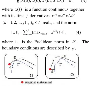
The surgeon handles freely the surgical instrument (red) starting from the distance d to a critical frontier Γ (blue) without robotic control, but when it reaches a critical point or area at the distance D<d from Γ, the robot intervenes and obliges the surgeon to stop the surgical instrument before reaching the final
point or to choose another route (Fig. 1). The concept of curvature bound set can generalize and unify all kind of critical points or frontiers for a second-order vector equation
( ) ( ( ), ( ), )
x t′′ = f x t x t t′ , x∈ Ω, t∈[ , ]t t0 1 ,
g x a x b x a x b( ( ), ( ), ( ), ( ))′ ′ =0, (3)
where x t( ) is a function continuous together with its first j derivatives ( )
/
k k k
x =d x dt
(k=1, 2,..., )j , t0<t1 reals, and the norm
( ) [ , ] 0
|| || j [max | k ( ) |] j k t a b
x =
∑
= ∈ x t , (4)where | |⋅ is the Euclidean norm in n
R . The boundary conditions are described by g.
Fig. 1. Crossing critical frontiers Γ in the surgery control.
The paper is organized as follows: Section 2 is devoted to kinematics and dynamics of the robot. The nonlinear boundary problem is shortly described in Section 3, and the Section 4 presents the results. Conclusions are drawn in Section 5.
2. KINEMATICS AND DYNAMICS OF THE ROBOT
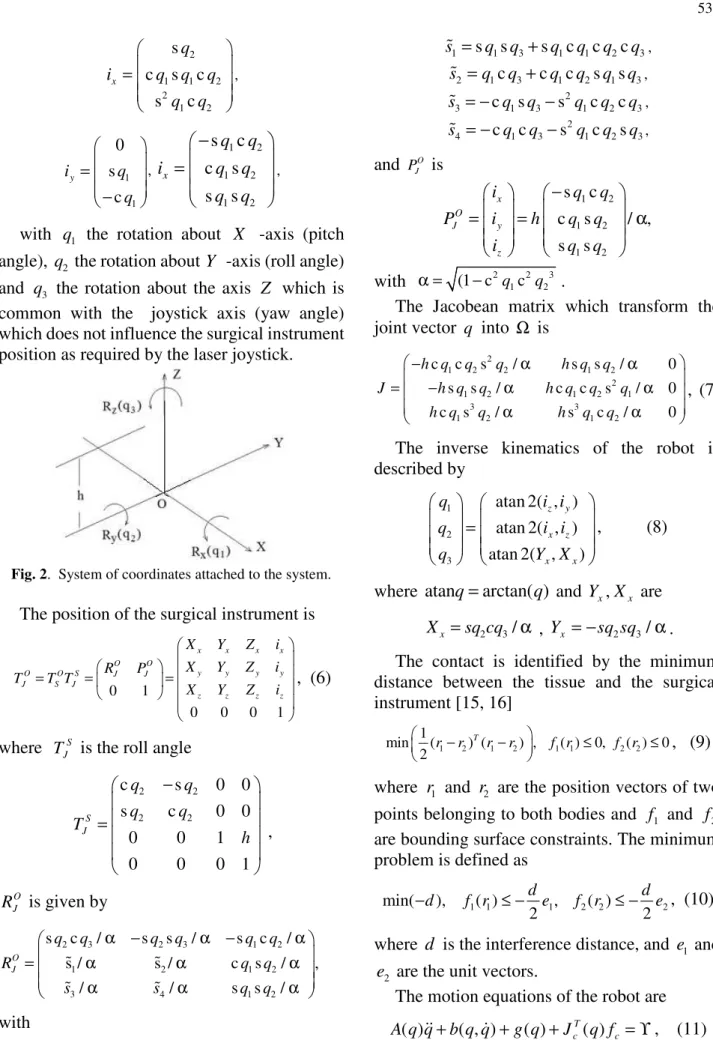
The working space Ω is defined by the coordinates( , , )x y z . The motion of the surgical instrument is simulated by the virtual joystick situated at the height from the base of the robot. A system of coordinates is attached to the base of the robot as shown in Fig 2, where
1 2 3
( , , )
q= q q q is the joint vector. The transformation matrix is [14]
2 2 2 2
1 2 1 2
/ 1 c c / 1 c c 0
0 0 0 1
O x y z
S
i q q i i q q
T
− −
=
(5)
2
1 1 2 2
1 2
s
c s c
s c
x
q
i q q q q q = , 1 1 0 s c y i q q = − , 1 2 1 2 1 2 s c c s s s x q q
i q q
q q − = ,
with q1 the rotation about X -axis (pitch
angle), q2 the rotation about Y -axis (roll angle)
and q3 the rotation about the axis Z which is common with the joystick axis (yaw angle) which does not influence the surgical instrument position as required by the laser joystick.
Fig. 2. System of coordinates attached to the system.
The position of the surgical instrument is
0 1
0 0 0 1
x x x x
O O
y y y y
O O S J J
J S J
z z z z
X Y Z i
X Y Z i
R P
T T T
X Y Z i
= = =
, (6)
where S J
T is the roll angle
2 2
2 2
c s 0 0
s c 0 0
0 0 1
0 0 0 1
S J q q q q T h − = , O J
R is given by
2 3 2 3 1 2
1 2 1 2
3 4 1 2
s c / s s / s c /
s / s / c s / ,
/ / s s /
O J
q q q q q q
R q q
s s q q
α − α − α
= α α α
α α α
% %
% %
with
1 s 1s 3 s 1c 1c 2c 3
s% = q q + q q q q , 2 1c 3 c 1c 2s 1s 3
s% =q q + q q q q , 2
3 c 1s 3 s 1c 2c 3
s% = − q q − q q q , 2
4 c 1c 3 s 1c 2s 3
s% = − q q − q q q ,
and O J P is
1 2
1 2
1 2
s c
c s / ,
s s
x O
J y
z
i q q
P i h q q
i q q
−
= = α
with α = (1 c− 2q1c2q23 .
The Jacobean matrix which transform the joint vector q into Ω is
2
1 2 2 1 2
2
1 2 1 2 1
3 3
1 2 1 2
c c s / s s / 0
s s / c c s / 0
c s / s c / 0
h q q q h q q
J h q q h q q q
h q q h q q
− α α
= − α α
α α
, (7)
The inverse kinematics of the robot is described by
1
2
3
atan 2( , ) atan 2( , )
atan 2( , )
z y
x z
x x
q i i
q i i
q Y X
=
, (8)
where atanq=arctan( )q and Yx,Xx are
2 3/
x
X =sq cq α , Yx = −sq sq2 3/α.
The contact is identified by the minimum distance between the tissue and the surgical instrument [15, 16]
1 2 1 2 1 1 2 2
1
min ( ) ( ) , ( ) 0, ( ) 0
2
T
r r r r f r f r
− − ≤ ≤
, (9)
where r1 and r2 are the position vectors of two
points belonging to both bodies and f1 and f2
are bounding surface constraints. The minimum problem is defined as
1 1 1 2 2 2
min( ), ( ) , ( )
2 2
d d
d f r e f r e
− ≤ − ≤ − , (10)
where d is the interference distance, and e1 and
2
e are the unit vectors.
The motion equations of the robot are
( ) ( , ) ( ) T( )
c c
where q=( ,q q q1 2, 3),A q b q q( ), ( , )& and g q( ) are the joint vector, the mass/inertia matrix, the Coriolis/centrifugal torque and the gravity torque in the joint space. The contact force is [17]
n p q
c
f
= δ + δ δ
k
%b
% &
, (12) where n p q%, , are constants, coefficient k
depends on the material and the geometric properties of the bodies in contact, and b% is defined with respect to the coefficient of restitution 0≤ ≤e 1.
3. NONLINEAR BOUNDARY VALUE PROBLEM
The critical points or frontiers are described by nonlinear boundary conditions very suitable to capture points, lines and curves. For example, the vascular territories schematized in Fig, 3, i.e. the portal vein (Fig. 3a), the hepatic veins (Fig. 3b), the hepatic artery (Fig. 3c) and the bile duct system (Fig. 3d) form a critical domain.
We consider the second order vector equation (3) and introduce the curvature bound and open set G defined on Ω ×[ , ]t t0 1 that satisfies the condition that if ∀( , )x t0 % ∈ ∂G, t%∈] , [t t0 1 , there
is a real function V : ( , )x t →V x t x t1( 0, , , )% such that [18]
2 0 1
([ , ]
, )
V
∪
C
t t
× Ω
R
,{( , ) : ( , ) 0}
G⊂ x t V x t < ,
V x t
( , )
0%
=
0
,grad , col(1, )
V
y
=
0
p
f
, (13)0
(col(1, )),col(1, )
grad , col(0, ( , , ))
0,
H
y
y
V
f x t y
+
+
>
p
f
%
p
f
where H and grad V are the gradient and the Hessian matrix of V at (x t0, )% for all y. This set can be autonomous in the sense that V can be taken independent of t and t% .
Fig. 3. The vascular critical domain: the portal vein (a), the hepatic veins (b), the hepatic artery (c) and the bile
duct system (d).
4. CONTROL
The control is concentrated on the stopping the surgical instrument to reach a irregular area containing points, lines and curves. The strategy is exercised on a domain that includes the portal vein, the hepatic veins, the hepatic artery and the bile duct system [19].
A fictive intraoperative sonogram during surgical hepatic treatment is presented in Fig. 4. In the figure we see red arrows directed towards deep round tumors (white). Here, the drugs should be introduced according to a known integrated imaging-molecular diagnosis.
Fig.5. The steps of the control.
To perform a sharp and almost bloodless trajectory with the surgical instrument, the task is composed from (Fig. 5): at the beginning the tumor is identified and a line is marked around it, at 1 or 2 cm to the tumor; at this point the surgical instrument (red) begins to move towards tumor to delivery of drugs into its tissue, and bypassing the forbidden lines (red). When it is getting close to the line, the robot intervenes by decreasing the surgical instrument speed proportionally to the distance to tumor. A buffer will mitigate the final stop inside the tumor with the progressive movements.
5. CONCLUSION
The original contribution of this paper consists in proposal of a control strategy based on dL for a cooperative surgeon-robot system whose behavior depends on the interaction between discrete and continuous dynamics. This strategy controls a virtual surgical robot composed by a system of tracking the position and orientation of the surgical instrument, a device for visualizing and analyzing the medical sonograms and a six degree-of-freedom robotic arm designed for use in hepatic surgery.
The task of the surgeon is the target delivery of drugs in tumor tissue, while the task of the robot is to stop the surgical instrument to reach a forbidden domain. The limitations of the current results in the literature refer to the ignoring of the nonlinear boundary conditions that describe the geometry of the forbidden area. To overcome this limitation, we introduce the boundary value conditions with nonlinear terms that are efficiently captured by dL. This strategy is exercised on the vascular territories composed
by the portal vein, the hepatic veins, the hepatic artery and the bile duct system.
Importantly, the new approach is suitable to capture irregular areas that include points, lines and curves and does not hinder the trajectory control.
Acknowledgement. This work was supported by a grant of the Romanian ministry of Research and Innovation, CCCDI – UEFISCDI, project number PN-III-P1-1.2-PCCDI-2017-0221/59 PCCDI/2018 (IMPROVE), within PNCDI III.
6. REFERENCES
[1] Platzer, A., Differential dynamic logics. Automated theorem proving fir hybrid systems, PhD Thesis, Carl Von Ossientzky Universitat Oldenburg, 2008.
[2] Platzer, A., Differential dynamic logic for hybrid systems, J. Autom. Reasoning, 41(2), 143–189, 2008.
[3] Platzer, A., Quesel, J.D., Keymaera: A hybrid theorem prover for hybrid systems, in: Automated Reasoning, 4th Int. Joint Conf., vol. 5195, A. Armando, P. Baumgartner and G. Dowek (eds.), pp.171-178, 2008, Springer Verlag, Berlin Heidelberg.
[4] Platzer, A., Clarke, E.M., Computing differential invariants of hybrid systems as fixed points, in: Gupta and Malik, Computer Aided Verification, CAV 2008, vol.5123, pp.176-189, 2008, Princeton, Springer, Berlin Heidelberg.
[5] Platzer, A., Clarke, E.M., Computing differential invariants of hybrid systems as fixed points, Formal Methods in System Design 35(1), 98– 120, 2009.
[6] Platzer, A., Logical analysis of hybrid systems- proving theorems for complex dynamics, 2010, Springer Verlag, Berlin Heidelberg.
[7] Platzer, A., A complete axiomatization of quantified differential dynamic logic for distributed hybrid systems, Logical Methods in Computer Science, 8(4), 1–44, 2012.
[8] Franzle, M., Herde, C., Hysat - An efficient proof engine for bounded model checking of hybrid systems, Formal Methods in System Design, 30(2), 179–198, 2007.
[10] Kazanzides, P., Virtual Fixture Computation, Note on Combining the Effects of Multiple Virtual Fixtures, 2011.
[11] Kouskoulas, Y., Platzer, A., Kazanzides, P., Formal methods for robotic system control software, Johns Hopkins Appl. Technical Digest, 32(2), 490-498, 2013.
[12] Eppinger, S., Seering, W., Understanding bandwidth limitations in robot force control, Proceeding IEEE International Conference on Robotics and Automation, 1987.
[13] Pisla, D., Birlescu, I., Vaida, C., Tucan, P., Pisla, A., Gherman, B., Crisan, N., Plitea, N., Algebraic modeling of kinematics and singularities for a prostate biopsy parallel robot, Proceedings of the Romanian Academy, series A, 19(3) 489-497, 2018
[14] Chiroiu, V., Munteanu, L., Rugina, C., On the control of a cooperatively robotic system by using a hybrid logic algorithm, Proceedings of the Romanian Academy, series A, 2018 (in press).
[15] Munteanu, L., Brisan, C., Chiroiu, V., Donescu, St., A 3D model for tire/road dynamic contact, Acta Technica Napocensis, Series: Applied Mathematics and mechanics, 55(3), 611–614, 2012.
[16] Munteanu, L., Chiroiu, V., Brişan, C., Dumitriu, D., Sireteanu, T., Petre, S., On the 3D normal tire/off-road vibro-contact problem with friction, Mechanical Systems and Signal Processing, 54-55, 377-393, 2014.
[17] Gilardi, G., Sharf, I., Literature survey of contact dynamics modelling, Mechanism and Machine Theory, 37, 1213–1239, 2002.
[18] Avramescu, C., Sisteme diferentiale cu conditii la limita generale, Bul. Inst. Politehn., Iasi, 11, 35-42, 1965.
[19] Lang, H., Hindennach, M., Radtke, A., Peitgen, H.O., Virtual Liver Surgery: Computer-assisted operation planning in 3D liver model, in Renzo Dionigi, Recent advances in liver surgery, Chapter 5, Landes Bioscience, Austin, Texas, USA, 2009.
Asupra unui model logic dinamic diferențial pentru sisteme hibride
Rezumat: Contribuția acestei lucrări constă în avansarea unei strategii de control bazată pe logica dinamică diferențială(dL) pentru un sistem cooperant chirurg-robot al cărui comportament depinde de interacțiunea dintre dinamica discretă care derivă din control și dinamica continuă care apare din mișcarea instrumentului chirurgical. Astfel de sisteme se numesc sisteme hibride. Algoritmul dL captează logica suprapunerii ambelor dinamici și este capabil să controleze sistemul în modul cel mai natural. După opinia noastră, dL poate fi utilizat cu succes pentru evitarea coliziunilor instrumentului chirurgical cu un domeniu critic într-un sistem virtual compus dintr-un robot chirurgical, un dispozitiv de vizualizare și analiză a imaginilor medicale și un braț robotic cu șase grade de libertate conceput pentru utilizare în chirurgia hepatică.
Cuvinte cheie: Control logic diferențial; Sisteme hibride; Chirurgie robotică; Evitarea coliziunii.
Veturia CHIROIU, PhD in Math., Senior researcher, Institute of Solid Mechanics, Romanian Academy, Deformable Media and Ultrasonics, Email: [email protected], Office Phone: +40213153810, Home Address: Aleea Costinesti nr. 10 Bucharest, Home Phone: +40216885181. Ligia MUNTEANU, PhD in Math., Senior researcher, Institute of Solid Mechanics, Romanian
Academy, Deformable Media and Ultrasonics, Email: [email protected], Office Phone: +40213153810, Home Address: Str. Minervei nr. 79 Bucharest, Home Phone: +40724701227.
Ciprian DRAGNE, Mechanical Engineer, Researcher assistant, Institute of Solid Mechanics, Romanian Academy, Deformable Media and Ultrasonics, Email: [email protected], Office Phone: +40213153810, Home Address: Aleea Motistea nr. 39 Bucharest, Home Phone: +40788914948.