1. R. Elmansouri, S. Meghzili, A. Chaoui and O. Hedjazi are with MISC Laboratory, Department of Computer Science and Its Applications, Faculty of NTIC, University Constantine 2 - Abdelhamid Mehri, Constantine, Algeria. Emails: raida.elmansouri@univ-constantine2.dz, meghzili.said.1989@gmail.com, allaoua.chaoui@univ-constantine2.dz and hedjazi@mjustice.dz
2. A. Belghiat is with University of Jijel, Algeria. Email: belghiatissam@gmail.com
I
NTEGRATING
UML
2.0
A
CTIVITY
D
IAGRAMS AND
P
I
-CALCULUS FOR
M
ODELING AND
V
ERIFICATION OF
S
OFTWARE
S
YSTEMS
U
SING
TGG
Raida Elmansouri
1, Said Meghzili
1, Allaoua Chaoui
1, Aissam Belghiat
2and Omar
Hedjazi
1(Received: 18-Apr.-2020, Revised: 18-Jun.-2020 and 26-Jul.-2020, Accepted: 24-Aug.-2020)
A
BSTRACTThis paper deals with modeling and verification of software systems by combining UML diagrams and Pi-calculus. UML 2.0 Activity diagrams are used for modeling the behavior of software systems, while Pi-calculus is used for semantic and verification purposes. More precisely, UML is a semi-formal language and so it needs formal semantics for its constructs and lacks tools for verifying properties. To this end, we propose an approach and a tool called AD2PICALC for transforming UML 2.0 Activity diagrams to Pi-calculus processes using Eclipse Xpand and TGG tools. The obtained Pi-calculus processes are then used as input for Pi-calculus tools, like MWB, to verify some properties as deadlocks, safety, determinism, termination and livelock. We illustrate our contribution through an example from the literature and verify the property of deadlock using MWB tool. The main contribution of this paper lies in the automation of the transformation approach using TGG tools.
K
EYWORDSModel-driven engineering, TGG, Xpand, UML activity diagrams, Pi-calculus, Model transformation, Graph transformation, Software systems.
1.
I
NTRODUCTIONA critical system is a system the "failure" of which is a threat to human life, to the environment of the system or to the existence of the organization that manages it. Examples of critical systems include - among others- communication systems, embedded control systems, command and control systems and transport systems. The cost of a failure in a critical system could exceed the cost of the system itself. Nowadays, most of critical systems are computer-based. Therefore, to develop powerful and sophisticated software, the modeling and verification of such systems seem to be the best solution for such task. Specifically, modeling facilitates the understanding of their complex behavior and also simulates these systems, while verification ensures their accuracy. The combination of UML diagrams and formal methods is a very suitable approach for the development of software systems [1]-[2]. Unified Modeling Language (UML) [3] is a well-known standard notation used to model object oriented software systems. It provides methods that are structured, semi-formal and graphical for specification, but not suitable for verification and validation of software systems. UML has different kinds of structural and behavioral diagrams. Each diagram is dedicated to a description of different aspects of a complex (software) system. UML Activity diagrams are used to model easily the dynamic behavior of workflow systems. One of their main purposes is to model software processes and business processes and represent control flows between activities. On the other hand, formal methods are used in software engineering to reason about mathematical models by proving or verifying properties (e.g. deadlock) of models. They are used to ensure that these systems are developed without error; i.e., these systems are free of deadlock, safe, deterministic, terminating and free of livelock. However, the analysis and design work with formal methods is very expensive and requires mathematical skills. To bridge the gap between formal methods and semi-formal ones [4], several researchers proposed approaches allowing the integration of formal models supporting formal verification in semi-formal models.
In the present work, our main contribution consists of an integrated approach and a tool (called AD2PICALC) combining UML 2.0 activity diagrams and Pi-calculus [5]-[6] for the development of software systems. This approach is based on modeling, meta-modeling and model transformation, which are the fundamental concepts of Model Driven Engineering (MDE) [7]. Indeed, MDE is an active research area in both academia and industry. It aims to decrease the complexity of software development. It allows portability, interoperability and reuse. In this paper, we propose another way and a tool for transforming UML 2.0 Activity diagrams to Pi-calculus. This approach is based on Xpand [8] and TGG tool [9] which permits a bidirectional approach. As a semi-formal notation, UML 2.0 Activity diagrams need formal semantics. So, to implement a formal analysis of a UML activity diagram specification, we propose to translate it to Pi-calculus process. Therefore, the obtained process model can be automatically verified (whether it satisfies or not certain properties, such as deadlock) using Pi-calculus analytical tools, such as MWB [10]. Pi-calculus is a simple mathematical process model based on CCS, which stands for Calculus Communicating System, a language proposed by Milner in 1980 [11]. It belongs to the family of process algebras. Since UML activity diagrams are graphs, the proposed approach is based on graph grammars. TGG is used to implement the graph grammar.
The rest of the paper is organized as follows. In Section 2, we discuss some related works. In Section 3, we recall some basic concepts about UML 2.0 activity diagrams, Pi-calculus and graph grammars. In Section 4, we propose our approach and tool that combine UML 2.0 activity diagrams and Pi-calculus process algebra for the development of software systems. In Section 5, we apply our approach on an illustrative example from the literature. Section 6 concludes the paper and gives some perspectives of this research work.
2.
R
ELATEDW
ORKMany works tackled the problem of formalizing UML Activity diagram through translating it to formal standards supported by analysis facilities. In [12], the authors proposed activity diagram patterns for modeling business processes and a semantics for the activity diagrams, formalized by colored Petri nets. In [13], the authors defined semantics for activity diagram of UML by means of regular expression and its equivalent transition system. Moreover, they proposed a formal verification and traceability method for any activity model with the help of Arden's lemma. In [14], the authors transformed automatically UML 2.0 activity diagram to Petri nets. This transformation helps software designers analyze and verify properties using INA analyzer tool. In [15], the authors presented a transformation from Activity Diagram into its semantically equivalent Colored Petri Nets using Weighted Directed Graph. This transformation consists of two steps. In the first step, the UML Activity Diagram is transformed into a Weighted Directed Graph and in the second step, the Weighted Directed Graph is transformed into semantically equivalent Colored Petri Nets. In [16], the authors proposed a framework that provides formal definitions for UML Activity diagrams by transforming them to a formal representation called point graph (PG). The approach is illustrated with a case study at King’s College Hospital to improve patient flows of an accident and emergency department. In [17], the authors developed a specific tool, called MAV-UML-AD, allowing the specification and the verification of workflow models using UML activity diagrams and Event-B. The developed tool transforms an activity diagram model into an equivalent Event-B specification according to a mathematical semantics. They illustrated the use of the developed tool MAV-UML-AD using an example of specification and verification. In [18], the authors presented an approach that transforms the UML sequence diagrams, behavioural state machines and activity diagrams into a single Transition System to support model checking using NuSMV tool [19]. In [20] and [21], the authors presented an approach based on SCALA, an environment of executing Isabelle/HOL specifications that allows to transform UML State machine diagrams to Colored Petri Nets models. The authors also proved the correctness of certain structural properties of this transformation.
Several approaches proposed semantics for UML diagrams using process algebras, like Pi-calculus. In [22], the authors have proposed an automatic translation of UML specifications made up of sequence and state diagrams into Pi-calculus processes. The central point of their proposed translation was the coherence of the two types of diagrams. In [23], the authors proposed an approach for mapping only UML state machine diagrams into Pi-calculus using TGG tool. In [24], the authors presented an
approach for capturing and verifying dynamic program behaviors using UML communication diagrams and Pi-calculus. In [25], the authors proposed an approach based on ATOM³ tool [26] for mapping UML 2.0 Activity diagrams to Pi-calculus. Other works used Petri nets and their extensions, like Colored Petri nets to formalize UML diagrams. In [27], the authors presented π-calculus semantics as a formal basis for UML activity diagrams. They showed manually and formally the consistency between the concepts of activity diagrams and π-calculus expressions. In our present paper, we propose an automatic mapping using TGGs tools [9] based on ideas presented in [27]. The main differences between our approach and the previously cited approaches of transforming UML diagrams to π-calculusare summarized in the following table.
Used UML Diagrams Manual Automatic Used Transformation Tool [22] Activity, sequence and
state charts
x
[23] State chart x TGG
[24] Communication x
[25] Activity x ATOM3
[27] Activity x
Our Approach Activity x TGG
The use of TGG graph transformation tool instead of ATOM3 is due to its ability to perform complex
transformation and offer the capabilities needed to realize our ideas. Moreover, we have applied our approach and the developed tool on a complex illustrative example.
3.
B
ACKGROUNDIn the following sub-sections, we briefly recall some basic concepts about UML 2.0 Activity diagrams, Pi-calculus and graph grammars.
3.1
UML Activity Diagrams
Activity diagram is an important UML diagram to describe dynamic aspects of a system. Activity diagram is the object-oriented equivalent of flow charts and Data Flow Diagrams (DFDs) from structured software development. It is used to represent the flow from one activity to another activity. The activity describes a particular operation of the system. So, the control flow is drawn from one operation to another. This flow can be sequential, branched or concurrent. Activity diagrams allow dealing with all types of flow control by means of different elements, like initial, flow final, activity final, decision, merge, fork and join nodes. For more details, the reader is referred to [3].
3.2
Pi-calculus
The Pi-calculus [5] is an extension of CCS [11]. It is a process algebra where processes interact by sending communication links to each other. It can be considered as a mathematical model of processes the interconnections of which change when they communicate [6]. The transfer of a communication link between two processes is the basic computational operation. Then, the link is used for further interaction with other processes. Pi-calculus offers primitives for describing and analyzing global distributed infrastructure, focusing on process migration between peer process interaction via dynamic channel-private channel communication. Example applications include languages supporting distributed programming with process mobility: polyphonic C#, BPML description and analysis of authentication protocols: spi calculus typed processes to ensure fine-grained resource access control. For more details, see the excellent introduction to the Pi-calculus by Joachim Parrow [6].
3.3
Graph Grammars and TGG
In the following part, we recall some concepts about graph grammars and TGG. 3.3.1 Graph Grammars
Before presenting the idea of TGGs, we begin with graph grammars [28]. A graph grammar evolves from Chomsky grammar on strings to graphs. It consists of a set of graph-rewriting rules. Each one
has a graph at its Left Hand Side (LHS) and another graph at its Right Hand Side (RHS), as shown in Figure 1.
Figure 1. LHS and RHS of a rule.
The semantics of a graph grammar rule is similar to classical grammars in formal languages. A graph grammar rule can be applied to some graph called host graph. If the LHS of the rule matches a part of the host graph, this part is replaced by the RHS of the rule.
3.3.2 Triple Graph Grammars (TGGs)
Triple Graph Grammars (TGGs) have been proposed by Andy Schϋrr in 1994 for model transformation using graph grammars [28]. They allow the user to define a transformation (in both directions) in a declarative way. More precisely, Triple Graph Grammars (TGGs) are used for defining the correspondence between two different types of models via sets of corresponding graphs [29]. Each element of this set is a triple consisting of two independent graphs that are linked via a third graph, called the correspondence graph. Because of this triple structure, such a graph is also called a triple graph. These different graphs in a triple graph are typed over different type graphs. TGG rules are non-deleting graph production rules that describe how, based on a start graph or axiom, triple graphs can be created. Triple graphs that can be created by a TGG are called valid triple graphs. Transferred to the modeling world, TGGs define sets of corresponding models, also called triple models, where the independent models, called domain models, are instances of different meta-models. The domain models are linked via a correspondence model, which is an instance of a correspondence meta-model. The advantages of TGGs reside in the fact that the definition can be made operational, so that one model can be transformed into the other in either direction; even more, TGGs can be used to synchronize and maintain the correspondence of the two models, even if both of them are changed independently of each other; i.e., TGGs work in an incremental way.
3.3.3 Description of a TGG Rule
It is important to notice that the models to be transformed by TGGs will be represented as object diagrams; and a class diagram represents the set of models to be considered (meta-model). So, a TGG rule consists of nodes and arcs that represent objects and links in the domain models. LHS and RHS of a rule contain nodes and arcs. The old nodes and arcs are also called context nodes (nodes products) and edges of context (arcs products). The context nodes are shown as white boxes with a black border; nodes products are shown as green boxes with a border-dark green and labeled “+ +”. The arcs of context are shown as black arrows; arcs products are shown as arrows with dark green labeled ’’+ +”. Further constraints on attribute values and states of implementation can be formulated in a TGG rule. In a transformation, it has many strings as values of any price in the target model to be chained to different information in the source model. In a TGG rule, OCL expressions can be used in the constraints of attribute values and states of implementation. They are shown as rounded rectangles in yellow TGG rule [30].
4.
O
URA
PPROACHIn this section, we present an approach of mapping UML 2.0 Activity diagrams to Pi-calculus expressions. The objective of this transformation is to formally verify the desired properties of models using the analytical techniques and verification tools of Pi-calculus.
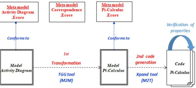
The main idea of our approach is depicted in Figure 2. It consists of three steps: (1) transforming an activity diagram into its equivalent Pi-calculus model using TGG, (2) generating the Pi-calculus code from the Pi-calculus model using eclipse Xpand code generator, (3) verifying the desired properties of the target model using the MWB Tools. In the following, we present first the meta-models, next the
transformation of activity diagrams to Pi-calculus processes using TGG tool and finally the translation of Pi-calculus models in abstract syntax to Pi-calculus code with Xpand tool.
Figure 2. The architecture of our approach.
4.1
Meta-models
We follow the approach of triple graph grammars (TGGs), where the abstract syntax of both activity diagrams and Pi-calculus expressions is represented by UML object diagrams. A third meta-model is used to capture the relation between corresponding elements of activity diagrams and Pi-calculus expressions. In the following, we give the three meta-models in detail.
4.1.1 UML Activity Diagram Meta-model
We propose in Figure 3 a modified version of the meta-model of UML activity diagram (as a UML class diagram) presented in [3]. The motivation behind the modification is to adapt it to our purpose, sine the meta-model of [3] is bigger. In this meta-model, the class ModelElement is abstract, since a concrete element is Activity, or ActivityPartition, or ActivityEdge, or ActivityNode. Activity is composed from three classes ActivityPartition, ActivityEdge and ActivityNode. ActivityNode can be
InitialNode, FinalNode, DecisionNode, MergeNode, ActionNode, ObjectNode, JoinNode or ForkNode. Activity Partition is composed from Activity Edge and Activity Node; Activity Edge can be
ControlFlow or ObjectFlow.
We have added to the ControlFlow class the following attributes:
- visitorIN (integer) to mark the input edges of JoinNode and MergeNode.
- FinIN (boolean) to mark the last input edge of JoinNode and MergeNode.
- visitorOUT (integer) to mark the output edges of ForkNode and DecisionNode. -FinOUT (boolean) to mark the last output edge of ForkNode and DecisionNode.
An example of how a simple activity diagram is represented according to this meta-model is shown in Figure 4. On the left side, we find the graphical representation of an activity diagram as a concrete syntax. On the right side, we find the same pattern in its abstract syntax represented as a UML object diagram needed by TGG.
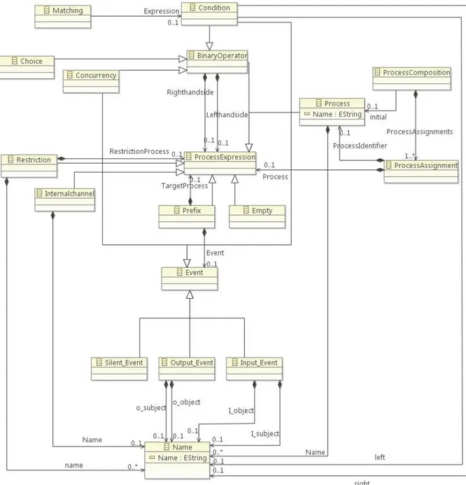
4.1.2 Pi-calculus Meta-model
Figure 5 shows the meta-model of the Pi-calculus processes. In this meta-model, there is a class for the root element ProcessComposition. This class is composed of a set of ProcessAssignments with at least one process. The left side of the assignment statement is the defined process (processIdentifier) and the right side refers to a ProcessExpression (process). The ProcessExpression can be an expression of Pi-calculus: Prefix, internalchannel, BinaryOperation, Restriction or Empty. A Prefix is composed of two parts; the left side one is an Event and the right side one is a ProcessExpression. An Event is: a
composed of a Name. An Input_Event consists of a Name. ABinaryOperator (Choice, Concurrency or Condition) consists of a ProcessExpression.A Process consists of a Name or more.
Figure 3. Adapted UML activity diagram meta-model from [3].
4.1.3 The Correspondence Meta-model
In defining the relationship between activity diagrams and Pi-calculus processes, we establish the relationship by additional nodes that refer to elements of both diagrams. These nodes are called nodes of correspondence. The exact meaning will be clearer when we define the matching rules in Section 4.2. Figure 6 shows the correspondence meta-model. We notice that these classes have other associations to classes of the two meta-models (Pi-calculus and activity diagrams), which are not shown in this diagram.
4.2
The Transformation of Activity Diagrams to Pi-calculus by a TGG Graph
Grammar
In this part, we propose twenty (20) rules for transforming UML Activity diagrams to Pi-calculus processes. We recall that the source and target models are expressed as UML object diagrams. The transformation scheme is based on [27], where activity diagram nodes are transformed to Pi-calculus processes, whereas activity diagram transitions are transformed to input or output channels (names). In the following, we give the idea of some transformation rules and their representation in TGG.
Figure 6. The correspondence model.
4.2.1 The Axiom
The axiom is the simplest relationship that transforms a simple activity diagram to Pi-calculus (Figure 7). On the right side of Figure 7, the process InitialProcess is still left open, as indicated by points then, that part will be supplemented by other rules later.
++ Activity: InitialProcess InitialProcess ( … )=(
v
… ) ...
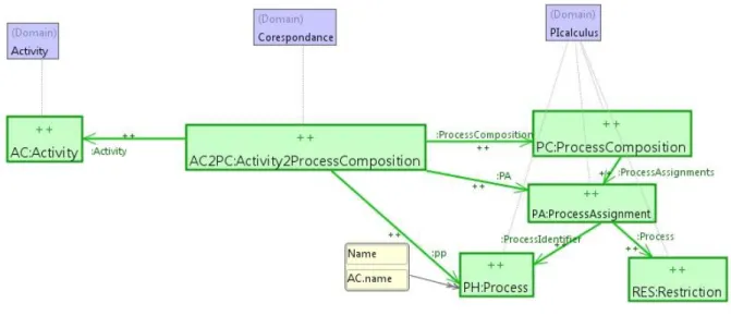
Figure 7. The idea of transforming an activity diagram into an initial process in Pi-calculus. The axiom shown in Figure 8 is the starting point of all transformations. An Activity corresponds to a
ProcessComposition, which contains a ProcessAssignement. On the left side of ProcessAssignement, there is a ProcessIdentifier (Process) which takes the name of the Activity by OCL expression. On the right side, there is a Process (Restriction). Every pair of object diagrams for Activity diagrams and Pi-calculus that can be constructed by applying the graph grammar rules, starting from this axiom at any matching position, represents a legal relation between the two kinds of models. This is the semantics of a set of TGG-rules. From this axiom, we will now discuss the new construction occurring in the activity diagram and show how the corresponding states are created in the Pi-calculus.
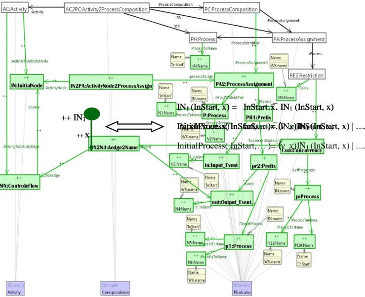
Figure 8. The axiom in TGG. 4.2.2 TGG Rule Transforming an Initial Node (InitialNode)
The idea of transforming an initial node is shown in Figure 9. At the left side, there is an initial node
the corresponding Pi-calculus code.
Figure 9. The idea of transforming the initial node into Pi-calculus in concrete syntax. This idea of transforming an initial node is expressed by the TGG rule in Figure 10.
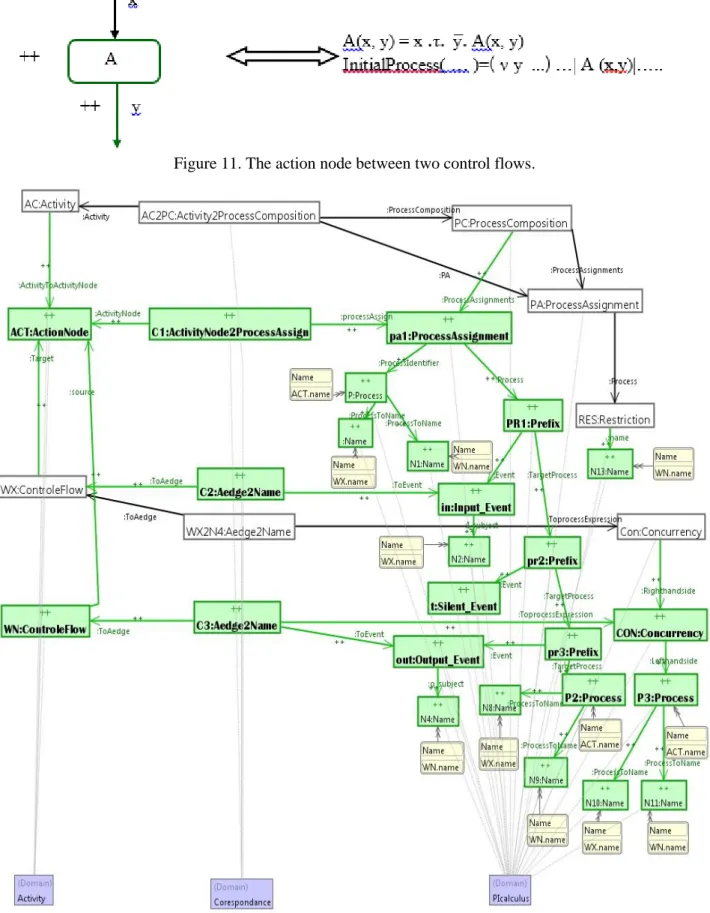
4.2.3 TGG Rule Transforming an Action Node (ActionNode)
The idea of transforming an action node is shown in Figure 11. We assume that the control flow x
exists and now an action A and a control flow y are added to the diagram (shown in green and marked with ++). Now, at the right side, a ProcessAssignment is composed of two parts: a right side
Process-Figure 10. TGG rule transforming an initial node.
Identifier A (x, y) and a left side ProcessExpression containing a Prefix process. For the InitialProcess, we add a local port y, an operator of concurrency (|) and the process A (x, y). The corresponding TGG rule is shown in Figure 12.
++ IN
1 ++ XIN
1(InStart, x) = InStart
.
x̅
.
IN
1(InStart, x)
InitialProcess( InStart,… )=
(
v
x
IN
1(InStart, x) | …
++ IN
1++ X
IN
1(InStart, x) = InStart
.
x̅
.
IN
1(InStart, x)
InitialProcess( InStart,… )=
(
v
x
IN
1(InStart, x) | …
++ IN
1++ X
IN
1(InStart, x) = InStart
.
x̅
.
IN
1(InStart, x)
InitialProcess( InStart,… )=
(
v
x
IN
1(InStart, x) | …
++ IN
1++ X
IN
1(InStart, x) = InStart
.
x̅
.
IN
1(InStart, x)
InitialProcess( InStart,… )=
(
v
x
IN
1(InStart, x) | …
IN
1(InStart, x) = InStart
.
x̅
.
IN
1(InStart, x)
InitialProcess( InStart,… )=
(
v
x
IN
1(InStart, x) | …
++ IN
1++ X
IN
1(InStart, x) = InStart
.
x̅
.
IN
1(InStart, x)
Figure 11. The action node between two control flows.
Figure 12. TGG rule transforming an Action node. 4.2.4 TGG Rule Transforming a Final Node (ActivityFinalNode)
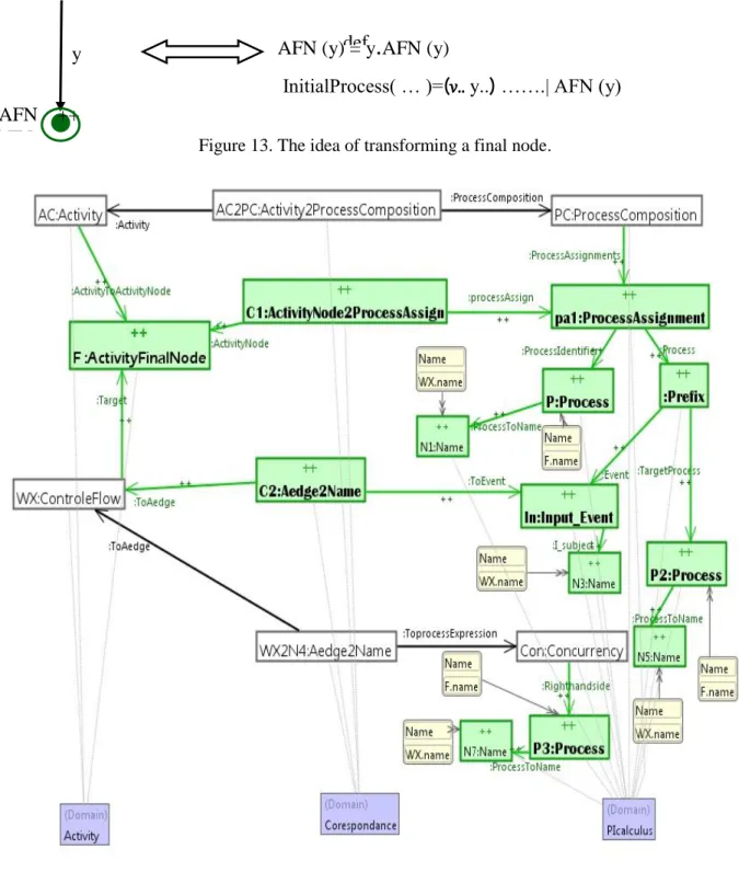
The idea of transforming a final node is shown in Figure 13. We assume that the controle flow y exists and now a final node FNA is added to the diagram (again shown by green color and marked with ++).
A new ProcessAssignment is generated which consists of two parts: the ProcessIdentifier AFN (y) at the right side and the prefix process y.AFN (y) at the left side. In the process InitialProcess, we add a local port y as well as the Process AFN (y). The corresponding TGG rule is shown in Figure 14
Figure 13. The idea of transforming a final node.
Figure 14. TGG rule for a final node.
Note: For lack of space, the reader is referred to our internal report [32] to see the rules of transforming the fusion node, the fork node, the join node and the decision node
4.3
Generating the Pi-calculus Code from the Pi-calculus Model
In order to check the correction of the target Pi-calculus models, we translate the Pi-calculus models in abstract syntax (conforming to meta-model) to Pi-calculus code (concrete syntax). This transformation is of model to text (M2T) type and is carried out using the Xpand tool of the EMF framework [31].
def
y
AFN ++
AFN
AFN (y) = y
.
AFN (y)
First, we use the Ecore meta-model of the source Pi-calculus shown in Figure 5. Second, we define the Xpand template shown in Figure 15. This template maps a calculus model in abstract syntax to Pi-calculas code.
Figure 15. The Xpand template defined to translate a Pi-calculus model to Pi-calculus code.
5. I
LLUSTRATIVEE
XAMPLE:
T
RANSFORMING ANA
CTIVITYD
IAGRAM TO AP
I-CALCULUS
E
XPRESSIONWe first deal with the transformation of the example. Then, we show the verification of Deadlock property using MWB Tool.
5.1 The Transformation Process
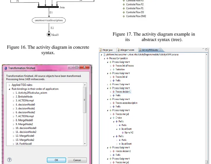
We have applied our approach on the example of Figure 16 representing an example of UML 2.0 Activity diagram borrowed from [33] with some modifications. We have first expressed this example
in its abstract syntax (tree), as shown in Figure 17. Then, we have executed our graph grammar on this example using the TGG interpreter, as depicted in Figure 18.
Figure 17. The activity diagram example in its abstract syntax (tree). Figure 16. The activity diagram in concrete
syntax.
Figure 18. Transforming the example Figure 19. The corresponding Pi-calculus of the activity using TGG interpreter. diagram example in abstract syntax.
As a result, we have obtained the Pi-calculus model (abstract syntax tree) shown in Figure 19. Then, we have used Xpand tool to transform the Pi-calculus model (abstract syntax as a tree) to its textual form and obtained the final Pi-calculus code shown in Figure 20.
Notation: The generated symbols of Pi-calculus are as follows: RESTRICTION: represented by the alphabet 'v'
OUT_EVENT: represented by the channel name + _BAR example: x = x_bar SILENT_EVENT: represented by 'Tau'
InitialProcess(InStart,nohelp,askhelp,else,else,real)=
( v S1 S2 M1 M2 M3 M4 DM1 DM2 D3 C1 F1 F2 F3 F4 J4 J3 J2 J1 C2 E1 E2)(Initial(InStart,S1) |(calldriver(S1,S2)|(((decision1(M1,S2,nohelp,askhelp,M2,M3,else)
|(assessdescription(M3,M4)|0))|(merge1(M2,DM1,M4)|((decision2(DM2,DM1,else,D3, real)|((((fork(F1,D3,F2,F3,F4)|(getD(F4,J4)|0))|(getC(F3,J3)|0))|(getB(F2,J2)|0))|(getA(F1,J1) |(join(E1,J1,J2,J3,J4)|(creatservicedescription(E1,E2)|final1(E2))))))|(merge2(DM2,C1,M1) |(creatalert(C1,C2)|final2(C2))))))|0)))
Initial(InStart,S1)= InStart.S1_BAR.Initial(InStart,S1) calldriver(S2,S1)= S1.Tau.S2_BAR.calldriver(S1,S2)
decision1(M1,S2,nohelp,M2,askhelp,else,M3)= S2.( v X)Cn_BAR<X>.X(Y).(
[Y=nohelp]M1_BAR. decision1(M1,S2,nohelp,M2,askhelp,else,M3)+([Y=askhelp]M2_BAR. decision1(M1,S2,nohelp,M2,askhelp,else,M3)+ [Y=else]M3_BAR. decision1(M1,S2,nohelp,M2,askhelp,else,M3)))
assessdescription(M4,M3)= M3.Tau.M4_BAR.assessdescription(M3,M4)
merge1(M2,DM1,M4) = (M2.DM1_BAR. merge1(M2,DM1,M4)+M4.DM1_BAR. merge1(M2,DM1,M4))
decision2(DM2,DM1,else,real,D3)= DM1.( v X)Cn_BAR<X>.X(Y).( [Y=else]DM2_BAR. decision2(DM2,DM1,else,real,D3)+ [Y=real]D3_BAR. decision2(DM2,DM1,else,real,D3))
merge2(DM2,C1,M1)= (DM2.C1_BAR. merge2(DM2,C1,M1)+M1.C1_BAR. merge2(DM2,C1,M1)) fork(F1,D3,F2,F3,F4)= D3.( v traversed)(F1_BAR.traversed_BAR.0|(F2_BAR.traversed_BAR.0| (F3_BAR.traversed_BAR.0|F4_BAR.traversed_BAR.0))).fork(F1,D3,F2,F3,F4)
getD(J4,F4)= F4.Tau.J4_BAR.getD(F4,J4) getC(J3,F3)= F3.Tau.J3_BAR.getC(F3,J3) getB(J2,F2)= F2.Tau.J2_BAR.getB(F2,J2) getA(J1,F1)= F1.Tau.J1_BAR.getA(F1,J1)
creatalert(C2,C1)= C1.Tau.C2_BAR.creatalert(C1,C2) final2(C2)= C2.final2(C2)
join(J1,E1,J2,J3,J4)=
( v received)(J1.received_BAR.0|(J2.received_BAR.0| (J3.received_BAR.0|J4.received_BAR.0))).E1_BAR.join(J1,E1,J2,J3,J4) creatservicedescription(E2,E1)=E1.Tau.E2_BAR.creatservicedescription(E1,E2)
final1(E2)= E2.final1(E2)
Figure 20. The final Pi-calculus expression.
5.2 Verification of Deadlock Property
In order to verify the deadlock property, we have first installed the Microsoft windows version of MWB Tool Version 4.137 under Standard ML of New Jersey (SML/NJ) Version 110.57 [34]. We will verify in the following the deadlock property on two examples: the illustrative example and another example with a deadlock.
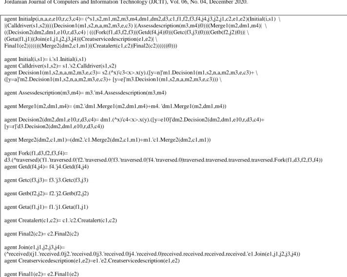
5.2.1 The Illustrative Example: with No Deadlock
The following subset has been taken as an input file process3.txt to MWB tool. We have adapted the pi-calculus expression of Figure 20 to the syntax of MWB, as shown in Figure 21.
agent Initialp(i,n,a,e,e10,r,c3,c4)= (^s1,s2,m1,m2,m3,m4,dm1,dm2,d3,c1,f1,f2,f3,f4,j4,j3,j2,j1,c2,e1,e2)(Initial(i,s1) \ |(Calldriver(s1,s2)|(((Decision1(m1,s2,n,a,m2,m3,e,c3) |(Assessdescription(m3,m4)|0))|(Merge1(m2,dm1,m4)| \ ((Decision2(dm2,dm1,e10,r,d3,c4) | (((Fork(f1,d3,f2,f3)|(Getd(f4,j4)|0)|(Getc(f3,j3)|0))|(Getb(f2,j2)|0))| \ (Geta(f1,j1)|(Join(e1,j1,j2,j3,j4)|(Creatservicedescription(e1,e2)| \
Final1(e2))))))|(Merge2(dm2,c1,m1)|(Creatalert(c1,c2)|Final2(c2))))))|0))) agent Initial(i,s1)= i.'s1.Initial(i,s1)
agent Calldriver(s1,s2)= s1.'s2.Calldriver(s1,s2)
agent Decision1(m1,s2,n,a,m2,m3,e,c3)= s2.(^x)'c3<x>.x(y).([y=n]'m1.Decision1(m1,s2,n,a,m2,m3,e,c3)+ \ ([y=a]'m2.Decision1(m1,s2,n,a,m2,m3,e,c3)+ [y=e]'m3.Decision1(m1,s2,n,a,m2,m3,e,c3))) \
agent Assessdescription(m3,m4)= m3.'m4.Assessdescription(m3,m4)
agent Merge1(m2,dm1,m4)= (m2.'dm1.Merge1(m2,dm1,m4)+m4. 'dm1.Merge1(m2,dm1,m4))
agent Decision2(dm2,dm1,e10,r,d3,c4)= dm1.(^x)'c4<x>.x(y).([y=e10]'dm2.Decision2(dm2,dm1,e10,r,d3,c4)+ [y=r]'d3.Decision2(dm2,dm1,e10,r,d3,c4))
agent Merge2(dm2,c1,m1)=(dm2.'c1.Merge2(dm2,c1,m1)+m1.'c1.Merge2(dm2,c1,m1)) agent Fork(f1,d3,f2,f3,f4)=
d3.(^traversed)('f1.'traversed.0|'f2.'traversed.0|'f3.'traversed.0|'f4.'traversed.0|traversed.traversed.traversed.traversed.Fork(f1,d3,f2,f3,f4)) agent Getd(f4,j4)= f4.'j4.Getd(f4,j4)
agent Getc(f3,j3)= f3.'j3.Getc(f3,j3) agent Getb(f2,j2)= f2.'j2.Getb(f2,j2) agent Geta(f1,j1)= f1.'j1.Geta(f1,j1)
agent Creatalert(c1,c2)= c1.'c2.Creatalert(c1,c2) agent Final2(c2)= c2.Final2(c2)
agent Join(e1,j1,j2,j3,j4)=
(^received)(j1.'received.0|j2.'received.0|j3.'received.0|j4.'received.0|received.received.received.received.'e1.Join(e1,j1,j2,j3,j4)) agent Creatservicedescription(e1,e2)=e1.'e2.Creatservicedescription(e1,e2)
agent Final1(e2)= e2.Final1(e2)
Figure 21. The final Pi-calculus expression respecting the syntax of MWB. This code is written in the file test14.txt.
We have applied the command input "test14.txt" on MWB followed by the command deadlock Name of the agent as follows:
F:\sml nj 110.57\mwb99-sources>sml @SMLload=mwb $* The Mobility Workbench
(MWB'99, version 4.137, built Fri Jul 24 18:10:22 2020) MWB>input "test14.txt"
MWB>deadlocks Geta No deadlocks found. MWB>deadlocks Getb No deadlocks found. MWB>deadlocks Getc No deadlocks found. MWB>deadlocks Fork No deadlocks found. MWB>deadlocks Join No deadlocks found. MWB>deadlocks Final1 No deadlocks found. MWB>deadlocks Final2 No deadlocks found. ...
MWB>
In conclusion, all the agents do not contain deadlock.
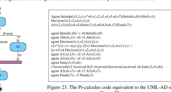
5.2.2 Example of UML-AD with the Presence of Deadlock
The UML Activity diagram shown in Figure 22 is used to illustrate the presence of a deadlock.
Agent Initialp(i,t1,f,c)=(^s0,s1,s2,s3,s4,s5,s6,s7)(Initial(i,s0)|A0(s0,s1)| Decision1(s1,s2,s4,t1,f,c)|\
A1(s2,s3)|A2(s4,s5)|Join(s3,s5,s6)|A3(s6,s7)|Final(s7)) agent Initial(i,s0)= i.'s0.Initial(i,s0)
agent A0(s0,s1)= s0.'s1.A0(s0,s1) agent Decision1(s1,s2,s4,t1,f,c)=
s2.(^x)'c<x>.x(y).([y=f]'s1.Decision1(s1,s2,s4,t1,f,c)+ \ [y=t1]'s4.Decision1(s1,s2,s4,t1,f,c))
agent A1(s2,s3)= s2.'s3.A1(s2,s3) agent A2(s4,s5)= s4.'s5.A2(s4,s5) agent Join(s3,s5,s6)=
(^received)(s3.'received.0|s5.'received.0|received.received.'s6.Join(s3,s5,s6)) agent A3(s6,s7)= s6.'s7.A3(s6,s7)
agent Final(s7)= s7.Final(s7)
Figure 23. The Pi-calculus code equivalent to the UML-AD of Figure 22.
Figure 22. Example of AD with deadlock presence.
First, we have transformed this UML-AD to its equivalent Pi-Calculus code, as shown in Figure 23. Then, we have executed the command input "deadlock1.txt" under MWB, followed by the command deadlocks Initialp, as follows:
F:\sml nj 110.57\mwb99-sources>sml @SMLload=mwb $* The Mobility Workbench
(MWB'99, version 4.137, built Fri Jul 24 18:10:22 2020) MWB>input "deadlock1.txt"
MWB>deadlocks Initialp
Deadlock found in (^~v,~v6,~v7,~v8,~v9,~v10,~v11,~v12)('~v.Initial<i,~v> | '~v6.A0<~v,~v6> | ~v7.(^x)'c<x>.x(y).([y=f]'~v6.Decision1<~v6,~v7,~v9,t1,f,c> + [y=t1]'~v9.Decision1<~v6,~v7,~v9,t1,f,c>) | ~v7.'~v8.A1<~v7,~v8> | ~v9.'~v10.A2<~v9,~v10> | (^received)(~v8.'received.0 | ~v10.'received.0 | received.received.'~v11.Join<~v8,~v10,~v11>) | ~v11.'~v12.A3<~v11,~v12> | ~v12.Final<~v12>)
reachable by 3 commitments MWB>
The response is that there is a deadlock. The interpretation of this deadlock is that the corresponding activity diagram has a design error. The result of the decision node is true or false. So, the join node will never be executed.
6. C
ONCLUSIONThis paper is a contribution in the area of model-driven engineering; it is essentially based on the combined use of meta-modeling and model transformation. We have proposed an integrated approach, supported by a tool called AD2PICALC, which combines UML 2.0 Activity diagrams and Pi-calculus process algebra for the development of software systems. More precisely, we have proposed an automated approach for transforming UML 2.0 Activity diagrams to Pi-calculus processes using Eclipse Xpand and TGG tools. First, we have proposed three meta-models; one for activity diagrams, the second for Pi-calculus and another one for correspondence. Second, we have presented the first transformation (TGG rule graph grammar) from UML activity diagram to Pi-calculus models using TGG tool. Finally, we have defined the second transformation that generates the Pi-calculus code from the Pi-calculus models (abstract syntax) using Xpand tool. We have illustrated our approach through an example from the literature. In a future work, we plan to apply our approach on several real case studies and use the Pi-calculus tools, such as MWB, to verify other properties of the modeled system, such as safety, non-determinism, termination and liveness. We plan also to transform other UML diagrams, like overview interaction diagrams. Finally, we plan to deal with the verification of the transformation itself based on the work published in [26].
A
CKNOWLEDGEMENTSThis work is supported by MISC laboratory, Faculty of NTIC, University Constantine 2-Abdelhamid Mehri, Constantine, Algeria and DGRSDT, Ministry of Higher Education and Scientific Research, Algeria.
R
EFERENCES[1] M. Singh, A. K. Sharma and R. Saxena, "An UML+ Z Framework for Validating and Verifying the Static Aspect of Safety Critical System," Procedia-Computer Science, vol. 85, pp. 352-361, 2016. [2] R. M. Borges and A. C. Mota, "Integrating UML and Formal Methods," Electronic Notes in
Theoretical Computer Science, vol. 184, pp. 97-112, 2007.
[3] OMG UML, [Online], Available: http://www.omg.org/spec/UML/2.2/Superstructure.
[4] F. R. Golra, F. Dagnat, J. Souquières, I. Sayar and S. Guerin, "Bridging the Gap Between Informal Requirements and Formal Specifications Using Model Federation," Proc. of the 16th International Conference on Software Engineering and Formal Methods (SEFM 2018), pp.
54-69, Toulouse, France, Jun. 2018,
[5] R. Milner, Communicating and Mobile Systems: The Pi Calculus, Cambridge University Press, 1999. [6] J. Parrow, "An Introduction to the Pi-calculus," Chapter to Appear in Handbook of Process Algebra,
Ed. Bergstra, Ponse and Smolka, Elsevier, [Online], Available: http://courses.cs.vt.edu/cs5204/fall09- kafura/Papers/PICalculus/Pi-calculus-Introduction.pdf.
[7] A. R. Da Silva, "Model-driven Engineering: A Survey Supported by the Unified Conceptual Model," Computer Languages, Systems & Structures, vol. 43, pp. 139-155, 2015.
[8] S. Efftinge, P. Friese, A. Hase, D. Hübner, C. Kadura, B. Kolb et al., "Xpand Documentation," Technical Report, Copyright 2004-2010, [Online], Available: https://git.eclipse.org/c/m2t/org.eclipse. xpand.git/plain/doc/org.eclipse.xpand.doc/manual/xpand_reference.pdf, 2004.
[9] TGG Home Page, [Online], Available: www.informatik.uni-marburg.de/~swtagtive-contest/. [10] B. Victor and F. Moller, "The Mobility Workbench—A Tool for the π-calculus," Proc. of the
International Conference on Computer Aided Verification, pp. 428-440, Springer, Berlin, Heidelberg, 1994.
[11] R. Milner, "A Calculus of Communicating Systems," Lecture Notes in Computer Science, vol. 92, 1980.
[12] É. André, C. Choppy and G. Reggio, "Activity Diagram Patterns for Modeling Business Processes," Software Engineering Research, Management and Applications, Part of Studies in Computational Intelligence, vol. 496, pp. 197-213, Springer, Heidelberg, 2014.
[13] B. Hazela, D. Arora and V. Saxena, "Formalizing Semantics for UML Activity Diagram through Regular Expression Translation," Research Journal of Applied Sciences, Engineering and Technology, vol. 11, no. 2, pp 169-175, 2015.
[14] Y. Rahmoune, A. Chaoui and E. Kerkouche, "A Framework for Modeling and Analysis of UML Activity Diagram Using Graph Transformation," Procedia-Computer Science, vol. 56, pp. 612-617, 2015.
[15] M. Jamal and N. A. Zafar, "Transformation of Activity Diagrams into Colored Petri Nets Using Weighted Directed Graph," Proc. of the IEEE International Conference on Frontiers of Information Technology (FIT), pp. 181-186, Islamabad, Pakistan, December 2016.
[16] I. Chishti, A. Basukoski, T. Chaussalet and N. Beeknoo, "Transformation of UML Activity Diagram for Enhanced Reasoning," Proceedings of the Future Technologies Conference, pp. 466-482, Springer, Cham, 2018.
[17] A. Achouri, Y. B. Hlaoui and L. J. B. Ayed, "Institution-based UML Activity Diagram Transformation with Semantic Preservation," International Journal of Computational Science and Engineering, vol. 18, no. 3, pp. 240-251, 2019.
[18] L. B. R. dos Santos, V. A. de Santiago Junior and N. L. Vijaykumar, "Transformation of UML Behavioral Diagrams to Support Software Model Checking," Proc. of Formal Engineering Approaches
to Software Components and Architectures (FESCA), vol. 147, pp. 133–142, doi:10.4204/EPTCS.147.10, 2014.
[19] NuSMV Home Page, "NuSMV: A New Symbolic Model Checker," [Online], Available: http://nusmv.fbk.eu/.
[20] S. Meghzili, A. Chaoui, M. Strecker and E. Kerkouche, "On the Verification of UML State Machine Diagrams to Colored Petri Nets Transformation Using Isabelle/HOL," Proc. of IEEE International Conference on Information Reuse and Integration (IRI), pp. 419-426, San Diego, CA, USA, 2017. [21] S. Meghzili, A. Chaoui, M. Strecker and E. Kerkouche, "Verification of Model Transformations Using
Isabelle/HOL and Scala," Information Systems Frontiers, vol. 21, no. 1, pp. 45-65, 2019.
[22] K. Pokozy-Korenblat and C. Priami, "Toward Extracting π-calculus from UML Sequence and State Diagrams," Electronic Notes in Theoretical Computer Science, vol. 101, pp. 51-72, 2004.
[23] A. Belghiat and A. Chaoui, "A TGG Approach for Bidirectional Automatic Mapping between UML and Pi-calculus," Proceedings of the International Conference on Intelligent Information Processing, Security and Advanced Communication, Article no. 70, pp. 1-3, [Online], Available: https://doi.org/10.1145/2816839.2816857, ACM, 2015.
[24] A. Belghiat, A. Chaoui and M. Beldjehem, "Capturing and Verifying Dynamic Program Behaviour Using UML Communication Diagrams and Pi-calculus," Proc. of IEEE International Conference on Information Reuse and Integration, pp. 318-325, San Francisco, CA, USA, 2015.
[25] A. Belghiat and A. Chaoui, "A Graph Transformation of Activity Diagrams into π-calculus for Verification Purpose," Proceedings of the 3rd Edition of the International Conference on Advanced
Aspects of Software Engineering (ICAASE18), pp. 107-114, Constantine, Algeria, Dec. 2018. [26] MSDL, "AToM3 Quick Links," [Online], Available: http://atom3.cs.mcgill.ca/.
[27] V. S. Lam, "On π-calculus Semantics As a Formal Basis for UML Activity Diagrams," International Journal of Software Engineering and Knowledge Engineering, vol. 18, no. 4, pp. 541-567, 2008. [28] A. Schürr, "Specification of Graph Translators with Triple Graph Grammars," Proc. of the International
Workshop on Graph-Theoretic Concepts in Computer Science, Lecture Notes in Computer Science, vol. 903, pp. 151-163, Springer, Berlin, Heidelberg, 1994.
[29] A. Königs, "Model Transformation with Triple Graph Grammars," Proc. of Model Transformations in Practice Satellite Workshop of MODELS, A., no. 166, pp. 1-16, [Online], Available: https://pdfs.semanticscholar.org/f608/40351e4f18c6513465956361b99a0eabb148.pdf, 2005.
[30] J. Greenyer and J. Rieke, "Applying Advanced TGG Concepts for a Complex Transformation of Sequence Diagram Specifications to Timed Game Automata," Proc. of the International Symposium on Applications of Graph Transformations with Industrial Relevance, pp. 222-237, Springer, Berlin, Heidelberg, 2011.
[31] F. Budinsky, D. Steinberg, E. Ellersick, T. J. Grose and E. Merks, Eclipse Modeling Framework: A Developer's Guide, Addison-Wesley Professional, 2004.
[32] R. Elmansouri, S. Meghzili, A. Chaoui, A. Belghiat and O. Hedjazi, "Transformation Rules of UML Activity Diagrams to Pi-calculus Using TGG," Internal Report, MFGL Team, MISC Laboratory, University Constantine 2-Abdelhamid Mehri, Algeria, [Online], Available: https://misc-lab.org/en/teams/show/MFGL.
[33] D. Bisztray, K. Ehrig and R. Heckel, "Case Study: UML to CSP Transformation," Applications of Graph Transformation with Industrial Relevance, [Online], Available: https://www.informatik.uni-marburg.de/~swt/agtive-contest/UML-to-CSP.pdf, 2007.
:ثحبلا صخلم
لااااااا ل اااااا ل اااااا لهاااااا ل اااااا ل ي ل هاااااار ا يلظااااااتطلنلظااااااقبتللظااااااربلا يلظاااااامن يلحبااااااولا هااااااعُت
ل هااااااااططخ
UML
ل اااااااا ه ي ل اااااااااهت يللهااااااااسح ل)
PI
ل هاااااااار هعت يل هااااااااططخ ل تخ ااااااااست ل.)
UML
2.0
ل اااااااهت يللهااااااسحل تخ ااااااس ل رااااااحل ااااااضلف هاااااار ا يلظااااااتطلنلم باااااانلظااااااقبت ل)
ل ااااااا ه ي
PI
ل اااااااضل نل ااااااا ا ل. ااااااا ل ي ل هااااااات لأيل ببتاااااااال ااااااابع تل ي اااااااغلأل)
UML
ل)
تااااااال اااااابع لهاااااااترضل اااااا ل هااااااط ل هااااااا لتل بااااااا لفظاااااار لاااااااااولظاااااا ل ااااااو
ل هااااااات لأيل بب
.ه صئهصخل ل ل ب لظ زلا يل ي لأيله ص تلهتكلفه تهارك
ل
ل اااااااااقنل ااااااااا
ل تاااااااااستل ي ن ل هااااااااا لى ااااااااا للف ااااااااا ذ
AD2PICALC
ل هاااااااااططخ ل ااااااااا ل ل)
ل هاااااار هعت ي
UML
2.0
ل ي نل يتخ اااااانهال اااااا ه ت ل اااااااهتتل هااااااربت ل اااااا يل)
Eclipse
Xpand
ل ل)
TGG
ل ختااااااااااتكلظاااااااااا ته يل هااااااااااربتع يل تخ ااااااااااسُتللاااااااااا ل اااااااااا ل.)
للهااااااااااسحل ي لأ
ل اااااااب لف ااااااا ه ي ل ااااااااهت ي
MWB
ل بهاااااااحل اااااااب لف ئهاااااااصخ يل ااااااا ل تااااااا ل ااااااا ل ااااااا ل ب ل؛
ل ااااا للاااااتلف اااااخنلظااااارحهلل ااااا ل. اااااراب ي لفرهااااا ل ي لفظااااارت ل ي لفظ لااااااس ي لف هااااا يلاااااام ي
لظرااااا هخل ااااا ل ااااا ل يل ااااا يلظضهاااااا هالفظاااااملاع يل يذل هااااارا لأيل ااااا لاهاااااب لالااااااخل ااااا له توهاااااس
ل ي نل يتخ ااااااانهال هااااااا يلاااااااام ي
MWB
ل اااااااضل ااااااالا يليبااااااا لظرااااااانهنلأيلظتوهاااااااست يل ااااااات ت ل.)
لظر لاب يلظرلهرا يل ن يلت ي مل ي نل يتخ نهال ل يلظ لظ تتن
TGG
.)
This article is an open access article distributed under the terms and conditions of the Creative Commons Attribution (CC BY) license (http://creativecommons.org/licenses/by/4.0/).
![Figure 3. Adapted UML activity diagram meta-model from [3].](https://thumb-us.123doks.com/thumbv2/123dok_us/8516073.2284043/6.892.120.799.200.732/figure-adapted-uml-activity-diagram-meta-model.webp)