ROOF ASSEMBLIES AND ROOFTOP STRUCTURES
SECTION 1501 GENERAL
1501.1 Scope. The provisions of this chapter shall govern the design, materials, construction and quality of roof assemblies, and rooftop structures.
SECTION 1502 DEFINITIONS
1502.1 Definitions. The following terms are defined in Chap-ter 2:
AGGREGATE. BALLAST.
BUILT-UP ROOF COVERING. INTERLAYMENT.
MECHANICAL EQUIPMENT SCREEN. METAL ROOF PANEL.
METAL ROOF SHINGLE.
MODIFIED BITUMEN ROOF COVERING. PENTHOUSE.
PHOTOVOLTAIC MODULES/SHINGLES. POSITIVE ROOF DRAINAGE.
REROOFING. ROOF ASSEMBLY. ROOF COVERING.
ROOF COVERING SYSTEM. ROOF DECK.
ROOF RECOVER. ROOF REPAIR.
ROOF REPLACEMENT. ROOF VENTILATION. ROOFTOP STRUCTURE. SCUPPER.
SINGLE-PLY MEMBRANE. UNDERLAYMENT.
SECTION 1503 WEATHER PROTECTION
1503.1 General. Roof decks shall be covered with approved roof coverings secured to the building or structure in accor-dance with the provisions of this chapter. Roof coverings shall be designed and installed in accordance with this code
and the approved manufacturer’s instructions such that the roof covering shall serve to protect the building or structure. 1503.2 Flashing. Flashing shall be installed in such a manner so as to prevent moisture entering the wall and roof through joints in copings, through moisture-permeable materials and at intersections with parapet walls and other penetrations through the roof plane.
1503.2.1 Locations. Flashing shall be installed at wall and roof intersections, at gutters, wherever there is a change in roof slope or direction and around roof openings. Where flashing is of metal, the metal shall be corrosion resistant with a thickness of not less than 0.019 inch (0.483 mm) (No. 26 galvanized sheet).
1503.3 Coping. Parapet walls shall be properly coped with noncombustible, weatherproof materials of a width no less than the thickness of the parapet wall.
1503.4 Roof drainage. Design and installation of roof drain-age systems shall comply with Section 1503 of this code and Sections 1106 and 1108, as applicable, of and the Plumbing
Code.
1503.4.1 Secondary (emergency overflow) drains or scuppers. Where roof drains are required, secondary (emergency overflow) roof drains or scuppers shall be pro-vided where the roof perimeter construction extends above the roof in such a manner that water will be entrapped if the primary drains allow buildup for any reason. The installation and sizing of secondary emergency overflow drains, leaders and conductors shall comply with Sections 1106 and 1108, as applicable, of the Plumbing Code. 1503.4.2 Scuppers. When scuppers are used for second-ary (emergency overflow) roof drainage, the quantity, size, location and inlet elevation of the scuppers shall be sized to prevent the depth of ponding water from exceed-ing that for which the roof was designed as determined by Section 1611.1. Scuppers shall not have an opening dimension of less than 4 inches (102 mm). The flow through the primary system shall not be considered when locating and sizing scuppers.
1503.4.3 Gutters. Gutters and leaders placed on the out-side of buildings, other than Group R-3, private garages and buildings of Type V construction, shall be of noncom-bustible material or a minimum of Schedule 40 plastic pipe.
1503.5 Roof ventilation. Intake and exhaust vents shall be provided in accordance with Section 1203.2 and the manufac-turer’s installation instructions.
1503.6 Crickets and saddles. A cricket or saddle shall be installed on the ridge side of any chimney or penetration greater than 30 inches (762 mm) wide as measured
perpen-dicular to the slope. Cricket or saddle coverings shall be sheet metal or of the same material as the roof covering.
Exception: Unit skylights installed in accordance with Section 2405.5 and flashed in accordance with the manu-facturer’s instructions shall be permitted to be installed without a cricket or saddle.
SECTION 1504
PERFORMANCE REQUIREMENTS
1504.1 Wind resistance of roofs. Roof decks and roof cover-ings shall be designed for wind loads in accordance with Chapter 16 and Sections 1504.2, 1504.3 and 1504.4.
1504.1.1 Wind resistance of asphalt shingles. Asphalt shingles shall comply with Section 1507.2.7.
1504.2 Wind resistance of clay and concrete tile. Wind loads on clay and concrete tile roof coverings shall be in accordance with Section 1609.5.
1504.3 Wind resistance of nonballasted roofs. Roof cover-ings installed on roofs in accordance with Section 1507 that are mechanically attached or adhered to the roof deck shall be designed to resist the design wind load pressures for compo-nents and cladding in accordance with Section 1609.
1504.3.1 Other roof systems. Roof systems with built-up, modified bitumen, fully adhered or mechanically attached single-ply through fastened metal panel roof systems, and other types of membrane roof coverings shall also be tested in accordance with FM 4474, UL 580 or UL 1897. 1504.3.2 Metal panel roof systems. Metal panel roof sys-tems through fastened or standing seam shall be tested in accordance with UL 580 or ASTM E 1592.
Exception: Metal roofs constructed of cold-formed steel, where the roof deck acts as the roof covering and provides both weather protection and support for struc-tural loads, shall be permitted to be designed and tested in accordance with the applicable referenced structural design standard in Section 2210.1.
1504.4 Ballasted slope roof systems. Ballasted low-slope (roof low-slope < 2:12) single-ply roof system coverings installed in accordance with Sections 1507.12 and 1507.13, and protected membrane ballasted low-slope (roof slope < 2:12) hot-applied rubberized-asphalt roofing systems installed in accordance with Section 1507.18, shall be designed in accordance with Section 1504.8 and ANSI/SPRI RP-4.
1504.5 Edge securement for low-slope roofs. Low-slope built-up, modified bitumen and single-ply roof system metal edge securement, except gutters, shall be designed and installed for wind loads in accordance with Chapter 16 and tested for resistance in accordance with Test Methods RE-1, RE-2 and RE-3 of ANSI/SPRI ES-1, except Vult wind speed
shall be determined from Figure 1609A, 1609B, or 1609C as applicable.
1504.6 Physical properties. Roof coverings installed on low-slope roofs (roof slope < 2:12) in accordance with
Sec-accelerated weathering tests conducted in accordance with ASTM G 152, ASTM G 155 or ASTM G 154. Those roof coverings that are subject to cyclical flexural response due to wind loads shall not demonstrate any significant loss of ten-sile strength for unreinforced membranes or breaking strength for reinforced membranes when tested as herein required.
1504.7 Impact resistance. Roof coverings installed on low-slope roofs (roof low-slope < 2:12) in accordance with Section 1507 shall resist impact damage based on the results of tests conducted in accordance with ASTM D 3746, ASTM D 4272, CGSB 37-GP-52M or the “Resistance to Foot Traffic Test” in Section 5.5 of FM 4470.
1504.8 Aggregate. Aggregate used as surfacing for roof cov-erings and aggregate, gravel or stone used as ballast shall not be used on the roof of a building located in a hurricane-prone region as defined in Section 202, or on any other building with a mean roof height exceeding that permitted by Table 1504.8 based on the exposure category and basic wind speed at the site.
TABLE 1504.8
MAXIMUM ALLOWABLE MEAN ROOF HEIGHT PERMITTED FOR BUILDINGS WITH AGGREGATE ON THE ROOF IN AREAS
OUTSIDE A HURRICANE-PRONE REGION
For SI: 1 foot = 304.8 mm; 1 mile per hour = 0.447 m/s. a. Mean roof height as defined in ASCE 7.
b. For intermediate values of Vasd, the height associated with the next higher value of Vasd shall be used, or direct interpolation is permitted.
c. NP = gravel and stone not permitted for any roof height. d. Vasd shall be determined in accordance with Section 1609.3.1.
SECTION 1505 FIRE CLASSIFICATION
1505.1 General. Roof assemblies shall be divided into the classes defined below. Class A, B and C roof assemblies and roof coverings required to be listed by this section shall be tested in accordance with ASTM E 108 or UL 790. In addi-tion, fire-retardant-treated wood roof coverings shall be tested in accordance with ASTM D 2898. The minimum roof coverings installed on buildings shall comply with Table 1505.1 based on the type of construction of the building.
NOMINAL DESIGN WIND SPEED, Vasd (mph)
b, d
MAXIMUM MEAN ROOF HEIGHT (ft)a, c
Exposure category
B C D
85 170 60 30
90 110 35 15
95 75 20 NP
100 55 15 NP
105 40 NP NP
110 30 NP NP
115 20 NP NP
120 15 NP NP
1505.2 Class A roof assemblies. Class A roof assemblies are those that are effective against severe fire test exposure. Class A roof assemblies and roof coverings shall be listed and iden-tified as Class A by an approved testing agency. Class A roof assemblies shall be permitted for use in buildings or struc-tures of all types of construction.
Exceptions:
1. Class A roof assemblies include those with cover-ings of brick, masonry or an exposed concrete roof deck.
2. Class A roof assemblies also include ferrous or cop-per shingles or sheets, metal sheets and shingles, clay or concrete roof tile or slate installed on non-combustible decks or ferrous, copper or metal sheets installed without a roof deck on noncombustible framing.
3. Class A roof assemblies include minimum 16 oz/sq. ft. (0.0416 kg/m2) copper sheets installed over
com-bustible decks.
1505.3 Class B roof assemblies. Class B roof assemblies are those that are effective against moderate fire-test exposure. Class B roof assemblies and roof coverings shall be listed and identified as Class B by an approved testing agency.
1505.4 Class C roof assemblies. Class C roof assemblies are those that are effective against light fire-test exposure. Class C roof assemblies and roof coverings shall be listed and iden-tified as Class C by an approved testing agency.
1505.5 Nonclassified roofing. Nonclassified roofing is
approved material that is not listed as a Class A, B or C roof
covering.
1505.6 Fire-retardant-treated wood shingles and shakes.
Fire-retardant-treated wood shakes and shingles shall be
treated by impregnation with chemicals by the full-cell vac-uum-pressure process, in accordance with AWPA C1. Each bundle shall be marked to identify the manufactured unit and the manufacturer, and shall also be labeled to identify the classification of the material in accordance with the testing
required in Section 1505.1, the treating company and the quality control agency.
1505.7 Special purpose roofs. Special purpose wood shingle or wood shake roofing shall conform with the grading and application requirements of Section 1507.8 or 1507.9. In addition, an underlayment of 5
/8-inch (15.9 mm) Type X
water-resistant gypsum backing board or gypsum sheathing shall be placed under minimum nominal 1
/2-inch-thick (12.7
mm) wood structural panel solid sheathing or 1-inch (25 mm) nominal spaced sheathing.
1505.8 Photovoltaic systems. Rooftop installed photovoltaic systems that are adhered or attached to the roof covering or photovoltaic modules/shingles installed as roof coverings shall be labeled to identify their fire classification in accor-dance with the testing required in Section 1505.1.
SECTION 1506 MATERIALS
1506.1 Scope. The requirements set forth in this section shall apply to the application of roof-covering materials specified herein. Roof coverings shall be applied in accordance with this chapter and the manufacturer’s installation instructions. Installation of roof coverings shall comply with the applica-ble provisions of Section 1507.
1506.2 Compatibility of materials. Roofs and roof cover-ings shall be of materials that are compatible with each other and with the building or structure to which the materials are applied.
1506.3 Material specifications and physical characteris-tics. Roof-covering materials shall conform to the applicable standards listed in this chapter. In the absence of applicable standards or where materials are of questionable suitability, testing by an approved agency shall be required by the
build-ing code official to determine the character, quality and
limi-tations of application of the materials.
1506.4 Product identification. Roof-covering materials shall be delivered in packages bearing the manufacturer’s identifying marks and approved testing agency labels required in accordance with Section 1505. Bulk shipments of materials shall be accompanied with the same information issued in the form of a certificate or on a bill of lading by the manufacturer.
SECTION 1507
REQUIREMENTS FOR ROOF COVERINGS 1507.1 Scope. Roof coverings shall be applied in accordance with the applicable provisions of this section and the manu-facturer’s installation instructions.
1507.2 Asphalt shingles. The installation of asphalt shingles shall comply with the provisions of this section.
1507.2.1 Deck requirements. Asphalt shingles shall be fastened to solidly sheathed decks.
1507.2.2 Slope. Asphalt shingles shall only be used on roof slopes of two units vertical in 12 units horizontal (17-percent slope) or greater. For roof slopes from two units
TABLE 1505.1a, b
MINIMUM ROOF COVERING CLASSIFICATION FOR TYPES OF CONSTRUCTION
For SI: 1 foot = 304.8 mm, 1 square foot = 0.0929 m2.
a. Unless otherwise required in accordance with the Wildland-Urban Interface Code or due to the location of the building within a fire district in accordance with Appendix D.
b. Nonclassified roof coverings shall be permitted on buildings of Group R-3 and Group U occupancies, where there is a minimum fire-separation distance of 6 feet measured from the leading edge of the roof.
c. Buildings that are not more than two stories above grade plane and having not more than 6,000 square feet of projected roof area and where there is a minimum 10-foot fire-separation distance from the leading edge of the roof to a lot line on all sides of the building, except for street fronts or public ways, shall be permitted to have roofs of No. 1 cedar or redwood shakes and No. 1 shingles constructed in accordance with Section 1505.7.
IA IB IIA IIB IIIA IIIB IV VA VB
vertical in 12 units horizontal (17-percent slope) up to four units vertical in 12 units horizontal (33-percent slope), double underlayment application is required in accordance with Section 1507.2.8.
1507.2.3 Underlayment. Unless otherwise noted, required underlayment shall conform to ASTM D 226, Type I, ASTM D 4869, Type I, or ASTM D 6757. 1507.2.4 Self-adhering polymer modified bitumen sheet. Self-adhering polymer modified bitumen sheet shall comply with ASTM D 1970.
1507.2.5 Asphalt shingles. Asphalt shingles shall comply with ASTM D 225 or ASTM D 3462.
1507.2.6 Fasteners. Fasteners for asphalt shingles shall be galvanized, stainless steel, aluminum or copper roofing nails, minimum 12 gage [0.105 inch (2.67 mm)] shank with a minimum 3
/8 inch-diameter (9.5 mm) head, of a
length to penetrate through the roofing materials and a minimum of 3
/4 inch (19.1 mm) into the roof sheathing.
Where the roof sheathing is less than 3
/4 inch (19.1 mm)
thick, the nails shall penetrate through the sheathing. Fas-teners shall comply with ASTM F 1667.
1507.2.7 Attachment. Asphalt shingles shall have the minimum number of fasteners required by the manufac-turer, but not less than four fasteners per strip shingle or two fasteners per individual shingle. Where the roof slope exceeds 21 units vertical in 12 units horizontal (21:12), shingles shall be installed as required by the manufacturer. 1507.2.7.1 Wind resistance. Asphalt shingles shall be tested in accordance with ASTM D 7158. Asphalt shin-gles shall meet the classification requirements of Table 1507.2.7.1(1) for the appropriate maximum basic wind speed. Asphalt shingle packaging shall bear a label to indicate compliance with ASTM D 7158 and the required classification in Table 1507.2.7.1(1).
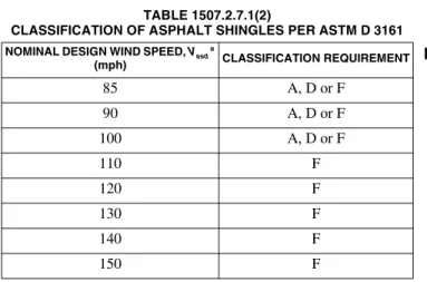
Exception: Asphalt shingles not included in the scope of ASTM D 7158 shall be tested and labeled to indicate compliance with ASTM D 3161 and the required classification in Table 1507.2.7.1(2).
TABLE 1507.2.7.1(1) CLASSIFICATION OF ASPHALT ROOF SHINGLES PER ASTM D 7158a
For SI: 1 foot = 304.8 mm; 1 mph = 0.447 m/s.
a. The standard calculations contained in ASTM D 7158 assume exposure category B or C and building height of 60 feet or less. Additional
TABLE 1507.2.7.1(2)
CLASSIFICATION OF ASPHALT SHINGLES PER ASTM D 3161
For SI: 1 mph = 0.447 m/s.
a. Vasd shall be determined in accordance with Section 1609.3.1.
1507.2.8 Underlayment application. For roof slopes from two units vertical in 12 units horizontal (17-percent slope) and up to four units vertical in 12 units horizontal (33-percent slope), underlayment shall be two layers applied in the following manner. Apply a minimum 19-inch-wide (483 mm) strip of underlayment felt parallel with and starting at the eaves, fastened sufficiently to hold in place. Starting at the eave, apply 36-inch-wide (914 mm) sheets of underlayment overlapping successive sheets 19 inches (483 mm), by fastened sufficiently to hold in place. Distortions in the underlayment shall not interfere with the ability of the shingles to seal. For roof slopes of four units vertical in 12 units horizontal (33-per-cent slope) or greater, underlayment shall be one layer applied in the following manner. Underlayment shall be applied shingle fashion, parallel to and starting from the eave and lapped 2 inches (51 mm), fastened sufficiently to hold in place. Distortions in the underlayment shall not interfere with the ability of the shingles to seal.
1507.2.8.1 High wind attachment. Underlayment applied in areas subject to high winds [Vasd greater than
110 mph (49 m/s) as determined in accordance with Section 1609.3.1] shall be applied with corrosion-resis-tant fasteners in accordance with the manufacturer's instructions. Fasteners are to be applied along the over-lap at a maximum spacing of 36 inches (914 mm) on center.
Underlayment installed where Vasd, in accordance
with Section 1609.3.1, equals or exceeds 120 mph (54 m/s) shall comply with ASTM D 226 Type II, ASTM D 4869 Type IV, or ASTM D 6757. The underlayment shall be attached in a grid pattern of 12 inches (305 mm) between side laps with a 6-inch (152 mm) spacing at the side laps. Underlayment shall be applied in accordance with Section 1507.2.8 except all laps shall be a mini-mum of 4 inches (102 mm). Underlayment shall be attached using metal or plastic cap nails with a head diameter of not less than 1 inch (25 mm) with a thickness of at least 32-gauge [0.0134 inch (0.34 mm)] sheet metal. The cap nail shank shall be a minimum of 12
NOMINAL DESIGN WIND SPEED, Vasd b
(mph) CLASSIFICATION REQUIREMENT
85 D, G or H
90 D, G or H
100 G or H
110 G or H
120 G or H
130 H
140 H
150 H
NOMINAL DESIGN WIND SPEED, Vasd a
(mph) CLASSIFICATION REQUIREMENT
85 A, D or F
90 A, D or F
100 A, D or F
110 F
120 F
130 F
140 F
through the roof sheathing or a minimum of 3/ 4 inch
(19.1 mm) into the roof sheathing.
Exception: As an alternative, adhered underlayment complying with ASTM D 1970 shall be permitted. 1507.2.8.2 Ice barrier. In areas where there has been a history of ice forming along the eaves causing a backup of water, an ice barrier that consists of at least two lay-ers of underlayment cemented together or of a self-adhering polymer modified bitumen sheet shall be used in lieu of normal underlayment and extend from the lowest edges of all roof surfaces to a point at least 24 inches (610 mm) inside the exterior wall line of the building.
Exception: Detached accessory structures that con-tain no conditioned floor area.
1507.2.9 Flashings. Flashing for asphalt shingles shall comply with this section. Flashing shall be applied in accordance with this section and the asphalt shingle manu-facturer’s printed instructions.
1507.2.9.1 Base and cap flashing. Base and cap flash-ing shall be installed in accordance with the manufac-turer’s instructions. Base flashing shall be of either corrosion-resistant metal of minimum nominal 0.019-inch (0.483 mm) thickness or mineral-surfaced roll roofing weighing a minimum of 77 pounds per 100 square feet (3.76 kg/m2
). Cap flashing shall be corro-sion-resistant metal of minimum nominal 0.019-inch (0.483 mm) thickness.
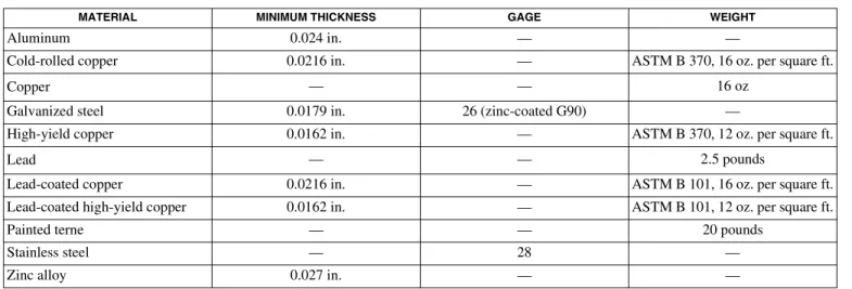
1507.2.9.2 Valleys. Valley linings shall be installed in accordance with the manufacturer’s instructions before applying shingles. Valley linings of the following types shall be permitted:
1. For open valleys (valley lining exposed) lined with metal, the valley lining shall be at least 24 inches (610 mm) wide and of any of the corro-sion-resistant metals in Table 1507.2.9.2. 2. For open valleys, valley lining of two plies of
mineral-surfaced roll roofing complying with
ASTM D 3909 or ASTM D 6380 shall be permit-ted. The bottom layer shall be 18 inches (457 mm) and the top layer a minimum of 36 inches (914 mm) wide.
3. For closed valleys (valleys covered with shin-gles), valley lining of one ply of smooth roll roof-ing complyroof-ing with ASTM D 6380, and at least 36 inches (914 mm) wide or types as described in Item 1 or 2 above shall be permitted. Self-adher-ing polymer modified bitumen underlayment complying with ASTM D 1970 shall be permitted in lieu of the lining material.
1507.2.9.3 Drip edge. Provide drip edge at eaves and gables of shingle roofs. Overlap to be a minimum of 2 inches (51 mm). Eave drip edges shall extend 1
/4 inch
(6.4 mm) below sheathing and extend back on the roof a minimum of 2 inches (51 mm). Drip edge shall be mechanically fastened a maximum of 12 inches (305 mm) o.c.
1507.3 Clay and concrete tile. The installation of clay and concrete tile shall comply with the provisions of this section.
1507.3.1 Deck requirements. Concrete and clay tile shall be installed only over solid sheathing or spaced structural sheathing boards.
1507.3.2 Deck slope. Clay and concrete roof tile shall be installed on roof slopes of 21
/2 units vertical in 12 units
horizontal (21-percent slope) or greater. For roof slopes from 21
/2 units vertical in 12 units horizontal (21-percent
slope) to four units vertical in 12 units horizontal (33-per-cent slope), double underlayment application is required in accordance with Section 1507.3.3.
1507.3.3 Underlayment. Unless otherwise noted, required underlayment shall conform to: ASTM D 226, Type II; ASTM D 2626 or ASTM D 6380, Class M min-eral-surfaced roll roofing.
1507.3.3.1 Low-slope roofs. For roof slopes from 21/ 2
units vertical in 12 units horizontal (21-percent slope), up to four units vertical in 12 units horizontal
(33-per-TABLE 1507.2.9.2 VALLEY LINING MATERIAL
For SI: 1 inch = 25.4 mm, 1 pound = 0.454 kg, 1 ounce = 28.35 g, 1 square foot = 0.093 m2.
MATERIAL MINIMUM THICKNESS GAGE WEIGHT
Aluminum 0.024 in. — —
Cold-rolled copper 0.0216 in. — ASTM B 370, 16 oz. per square ft.
Copper — — 16 oz
Galvanized steel 0.0179 in. 26 (zinc-coated G90) —
High-yield copper 0.0162 in. — ASTM B 370, 12 oz. per square ft.
Lead — — 2.5 pounds
Lead-coated copper 0.0216 in. — ASTM B 101, 16 oz. per square ft.
Lead-coated high-yield copper 0.0162 in. — ASTM B 101, 12 oz. per square ft.
Painted terne — — 20 pounds
Stainless steel — 28 —
cent slope), underlayment shall be a minimum of two layers applied as follows:
1. Starting at the eave, a 19-inch (483 mm) strip of underlayment shall be applied parallel with the eave and fastened sufficiently in place.
2. Starting at the eave, 36-inch-wide (914 mm) strips of underlayment felt shall be applied over-lapping successive sheets 19 inches (483 mm) and fastened sufficiently in place.
1507.3.3.2 High-slope roofs. For roof slopes of four units vertical in 12 units horizontal (33-percent slope) or greater, underlayment shall be a minimum of one layer of underlayment felt applied shingle fashion, par-allel to, and starting from the eaves and lapped 2 inches (51 mm), fastened only as necessary to hold in place. 1507.3.3.3 High wind attachment. Underlayment applied in areas subject to high wind [Vasd greater than
110 mph (49 m/s) as determined in accordance with Section 1609.3.1] shall be applied with corrosion-resis-tant fasteners in accordance with the manufacturer’s installation instructions. Fasteners are to be applied along the overlap not farther apart than 36 inches (914 mm) on center.
Underlayment installed where Vasd, in accordance
with Section 1609.3.1, equals or exceeds 120 mph (54 m/s) shall be attached in a grid pattern of 12 inches (305 mm) between side laps with a 6-inch (152 mm) spacing at the side laps. Underlayment shall be applied in accordance with Sections 1507.3.3.1 and 1507.3.3.2 except all laps shall be a minimum of 4 inches (102 mm). Underlayment shall be attached using metal or plastic cap nails with a head diameter of not less than 1 inch (25 mm) with a thickness of at least 32-gauge [0.0134 inch (0.34 mm)] sheet metal. The cap nail shank shall be a minimum of 12 gauge [0.105 inch (2.67 mm)] with a length to penetrate through the roof sheathing or a minimum of 3/
4 inch (19.1 mm) into the
roof sheathing.
Exception: As an alternative, adhered underlayment complying with ASTM D 1970 shall be permitted. 1507.3.4 Clay tile. Clay roof tile shall comply with ASTM C 1167.
1507.3.5 Concrete tile. Concrete roof tile shall comply with ASTM C 1492.
1507.3.6 Fasteners. Tile fasteners shall be corrosion resis-tant and not less than 11 gage, 5
/16-inch (8.0 mm) head, and
of sufficient length to penetrate the deck a minimum of 3
/4
inch (19.1 mm) or through the thickness of the deck, whichever is less. Attaching wire for clay or concrete tile shall not be smaller than 0.083 inch (2.1 mm). Perimeter fastening areas include three tile courses but not less than 36 inches (914 mm) from either side of hips or ridges and edges of eaves and gable rakes.
1507.3.7 Attachment. Clay and concrete roof tiles shall be fastened in accordance with Table 1507.3.7.
1507.3.8 Application. Tile shall be applied according to the manufacturer's installation instructions, based on the following:
1. Climatic conditions. 2. Roof slope.
3. Underlayment system. 4. Type of tile being installed.
1507.3.9 Flashing. At the juncture of the roof vertical sur-faces, flashing and counterflashing shall be provided in accordance with the manufacturer’s installation instruc-tions, and where of metal, shall not be less than 0.019-inch (0.48 mm) (No. 26 galvanized sheet gage) corrosion-resis-tant metal. The valley flashing shall extend at least 11 inches (279 mm) from the centerline each way and have a splash diverter rib not less than 1 inch (25 mm) high at the flow line formed as part of the flashing. Sections of flash-ing shall have an end lap of not less than 4 inches (102 mm). For roof slopes of three units vertical in 12 units hor-izontal (25-percent slope) and over, the valley flashing shall have a 36-inch-wide (914 mm) underlayment of either one layer of Type I underlayment running the full length of the valley, or a self-adhering polymer-modified bitumen sheet complying with ASTM D 1970, in addition to other required underlayment. In areas where the average daily temperature in January is 25°F (-4°C) or less or where there is a possibility of ice forming along the eaves causing a backup of water, the metal valley flashing underlayment shall be solid cemented to the roofing underlayment for slopes under seven units vertical in 12 units horizontal (58-percent slope) or self-adhering poly-mer-modified bitumen sheet shall be installed.
1507.4 Metal roof panels. The installation of metal roof pan-els shall comply with the provisions of this section.
1507.4.1 Deck requirements. Metal roof panel roof cov-erings shall be applied to a solid or closely fitted deck, except where the roof covering is specifically designed to be applied to spaced supports.
1507.4.2 Deck slope. Minimum slopes for metal roof pan-els shall comply with the following:
1. The minimum slope for lapped, nonsoldered seam metal roofs without applied lap sealant shall be three units vertical in 12 units horizontal (25-percent slope).
2. The minimum slope for lapped, nonsoldered seam metal roofs with applied lap sealant shall be one-half unit vertical in 12 units horizontal (4-percent slope). Lap sealants shall be applied in accordance with the
approved manufacturer’s installation instructions.
3. The minimum slope for standing seam of roof sys-tems shall be one-quarter unit vertical in 12 units horizontal (2-percent slope).
TABLE 1507.3.7
CLAY AND CONCRETE TILE ATTACHMENTa, b, c
For SI: 1 inch = 25.4 mm, 1 foot = 304.8 mm, 1 mile per hour = 0.447 m/s, 1 pound per square foot = 4.882 kg/m2. a. Minimum fastener size. Corrosion-resistant nails not less than No. 11 gage with 5/
16-inch head. Fasteners shall be long enough to penetrate into the sheathing 3/
4 inch or through the thickness of the sheathing, whichever is less. Attaching wire for clay and concrete tile shall not be smaller than 0.083 inch. b. Snow areas. A minimum of two fasteners per tile are required or battens and one fastener.
c. Roof slopes greater than 24:12. The nose of all tiles shall be securely fastened.
d. Horizontal battens. Battens shall be not less than 1 inch by 2 inch nominal. Provisions shall be made for drainage by a minimum of 1/
8-inch riser at each nail or by 4-foot-long battens with at least a 1/
2-inch separation between battens. Horizontal battens are required for slopes over 7:12.
e. Perimeter fastening areas include three tile courses but not less than 36 inches from either side of hips or ridges and edges of eaves and gable rakes. f. Vasd shall be determined in accordance with Section 1609.3.1.
GENERAL - CLAY OR CONCRETE ROOF TILE Maximum Nominal Design
Wind Speed, Vasd f (mph)
Mean roof height
(feet) Roof slope < 3:12 Roof slope 3:12 and over
85 0-60 One fastener per tile. Flat tile
without vertical laps, two fas-teners per tile.
Two fasteners per tile. Only one fastener on slopes of 7:12 and less for tiles with installed weight exceeding 7.5 lbs./sq. ft. having a width no greater than 16 inches.
100 0-40
100 >40-60
The head of all tiles shall be nailed. The nose of all eave tiles shall be fastened with approved clips. All rake tiles shall be nailed with two nails. The nose of all ridge, hip and rake tiles shall be set in a bead of roofer’s mastic.
110 0-60 The fastening system shall resist the wind forces in Section 1609.5.3.
120 0-60 The fastening system shall resist the wind forces in Section 1609.5.3.
130 0-60 The fastening system shall resist the wind forces in Section 1609.5.3.
All >60 The fastening system shall resist the wind forces in Section 1609.5.3.
INTERLOCKING CLAY OR CONCRETE ROOF TILE WITH PROJECTING ANCHOR LUGSd, e
(Installations on spaced/solid sheathing with battens or spaced sheathing) Maximum Nominal Design
Wind Speed, Vasd f (mph)
Mean roof height
(feet) Roof slope < 5:12 Roof slope 5:12 < 12:12
Roof slope 12:12 and over
85 0-60 Fasteners are not required.
Tiles with installed weight less than 9 lbs./sq. ft. require a minimum of one fastener per tile.
One fastener per tile every other row. All perimeter tiles require one fastener. Tiles with installed weight less than 9 lbs./sq. ft. require a mini-mum of one fastener per tile.
One fastener required for every tile. Tiles with installed weight less than 9 lbs./sq. ft. require a minimum of one fastener per tile.
100 0-40
100 >40-60
The head of all tiles shall be nailed. The nose of all eave tiles shall be fastened with approved clips. All rake tiles shall be nailed with two nails The nose of all ridge, hip and rake tiles shall be set in a bead of roofer's mastic.
110 0-60 The fastening system shall resist the wind forces in Section 1609.5.3.
120 0-60 The fastening system shall resist the wind forces in Section 1609.5.3.
130 0-60 The fastening system shall resist the wind forces in Section 1609.5.3.
All >60 The fastening system shall resist the wind forces in Section 1609.5.3.
INTERLOCKING CLAY OR CONCRETE ROOF TILE WITH PROJECTING ANCHOR LUGS (Installations on solid sheathing without battens)
Maximum Nominal Design Wind Speed, Vasd
f (mph)
Mean roof height
(feet) All roof slopes
85 0-60 One fastener per tile.
100 0-40 One fastener per tile.
100 > 40-60
The head of all tiles shall be nailed. The nose of all eave tiles shall be fastened with approved clips. All rake tiles shall be nailed with two nails The nose of all ridge, hip and rake tiles shall be set in a bead of roofer’s mastic.
110 0-60 The fastening system shall resist the wind forces in Section 1609.5.3.
120 0-60 The fastening system shall resist the wind forces in Section 1609.5.3.
130 0-60 The fastening system shall resist the wind forces in Section 1609.5.3.
1507.4.3 Material standards. Metal-sheet roof covering systems that incorporate supporting structural members shall be designed in accordance with Chapter 22. Metal-sheet roof coverings installed over structural decking shall comply with Table 1507.4.3(1). The materials used for metal-sheet roof coverings shall be naturally corrosion resistant or provided with corrosion resistance in accor-dance with the standards and minimum thicknesses shown in Table 1507.4.3(2).
1507.4.4 Attachment. Metal roof panels shall be secured to the supports in accordance with the approved manufac-turer’s fasteners. In the absence of manufacturer recom-mendations, the following fasteners shall be used:
1. Galvanized fasteners shall be used for steel roofs. 2. Copper, brass, bronze, copper alloy or 300 series
stainless-steel fasteners shall be used for copper roofs.
3. Stainless-steel fasteners are acceptable for all types of metal roofs.
1507.4.5 Underlayment and high wind. Underlayment applied in areas subject to high winds [Vasd greater than
110 mph (49 m/s) as determined in accordance with Sec-tion 1609.3.1] shall be applied with corrosion-resistant fasteners in accordance with the manufacturer’s installa-tion instrucinstalla-tions. Fasteners are to be applied along the overlap not farther apart than 36 inches (914 mm) on cen-ter.
Underlayment installed where Vasd, in accordance with
Section 1609.3.1, equals or exceeds 120 mph (54 m/s) shall comply with ASTM D 226 Type II, ASTM D 4869 Type IV, or ASTM D 1970. The underlayment shall be attached in a grid pattern of 12 inches (305 mm) between side laps with a 6-inch (152 mm) spacing at the side laps. Underlayment shall be applied in accordance with the manufacturer’s installation instructions except all laps shall be a minimum of 4 inches (102 mm). Underlayment shall be attached using metal or plastic cap nails with a head diameter of not less than 1 inch (25 mm) with a thickness of at least 32-gauge [0.0134 inch (0.34 mm)] sheet metal. The cap nail shank shall be a minimum of 12 gauge [0.105 inch (2.67 mm)] with a length to penetrate through the roof sheathing or a minimum of 3
/4 inch (19.1
mm) into the roof sheathing.
Exception: As an alternative, adhered underlayment complying with ASTM D 1970 shall be permitted.
TABLE 1507.4.3(1) METAL ROOF COVERINGS
For SI: 1 ounce per square foot = 0.305 kg/m2, 1 pound per square foot = 4.882 kg/m2, 1 inch = 25.4 mm, 1 pound = 0.454 kg.
a. For Group U buildings, the minimum coating thickness for ASTM A 653 galvanized steel roofing shall be G-60.
ROOF COVERING TYPE STANDARD APPLICATION RATE/THICKNESS
Aluminum
ASTM B 209, 0.024 inch minimum thick-ness for roll-formed panels and 0.019 inch minimum thickness for press-formed shingles.
Aluminum-zinc alloy coated steel
ASTM A 792 AZ 50
Cold-rolled copper
ASTM B 370 minimum 16 oz./sq. ft. and 12 oz./sq. ft. high yield copper for metal-sheet roof covering systems: 12 oz./sq. ft. for preformed metal shingle systems. Copper
16 oz./sq. ft. for metal-sheet roof-covering systems; 12 oz./sq. ft. for preformed metal shingle systems.
Galvanized steel ASTM A 653 G-90 zinc-coateda
.
Hard lead 2 lbs./sq. ft.
Lead-coated copper ASTM B 101
Prepainted steel ASTM A 755
Soft lead 3 lbs./sq. ft.
Stainless steel ASTM A 240, 300 Series Alloys
Steel ASTM A 924
Terne and terne-coated stainless
Terne coating of 40 lbs. per double base box, field painted where applicable in accordance with manufacturer’s installa-tion instrucinstalla-tions.
Zinc
0.027 inch minimum thickness; 99.995% electrolytic high grade zinc with alloy addi-tives of copper (0.08% - 0.20%), titanium (0.07% - 0.12%) and aluminum (0.015%).
TABLE 1507.4.3(2)
MINIMUM CORROSION RESISTANCE
a. Paint systems in accordance with ASTM A 755 shall be applied over steel products with corrosion-resistant coatings complying with ASTM A 792, ASTM A 875, ASTM A 463 or ASTM A 653.
55% Aluminum-zinc alloy coated steel ASTM A 792 AZ 50
5% Aluminum alloy-coated steel ASTM A 875 GF60
Aluminum-coated steel ASTM A 463 T2 65
Galvanized steel ASTM A 653 G-90
1507.5 Metal roof shingles. The installation of metal roof shingles shall comply with the provisions of this section.
1507.5.1 Deck requirements. Metal roof shingles shall be applied to a solid or closely fitted deck, except where the roof covering is specifically designed to be applied to spaced sheathing.
1507.5.2 Deck slope. Metal roof shingles shall not be installed on roof slopes below three units vertical in 12 units horizontal (25-percent slope).
1507.5.3 Underlayment. Underlayment shall comply with ASTM D 226, Type I or ASTM D 4869.
1507.5.3.1 Underlayment and high wind. Underlay-ment applied in areas subject to high winds [Vasd greater
than 110 mph (49 m/s) as determined in accordance with Section 1609.3.1] shall be applied with corrosion-resistant fasteners in accordance with the manufac-turer’s installation instructions. Fasteners are to be applied along the overlap not farther apart than 36 inches (914 mm) on center.
Underlayment installed where Vasd, in accordance
with Section 1609.3.1, equals or exceeds 120 mph (54 m/s) shall comply with ASTM D 226 Type II or ASTM D 4869 Type IV. The underlayment shall be attached in a grid pattern of 12 inches (305 mm) between side laps with a 6-inch spacing (152 mm) at the side laps. Underlayment shall be applied in accordance with the manufacturer’s installation instructions except all laps shall be a minimum of 4 inches (102 mm). Underlay-ment shall be attached using metal or plastic cap nails with a head diameter of not less than 1 inch (25 mm) with a thickness of at least 32-gauge [0.0134 inch (0.34 mm)] sheet metal. The cap nail shank shall be a mini-mum of 12 gauge [0.105 inch (2.67 mm)] with a length to penetrate through the roof sheathing or a minimum of 3
/4 inch (19.1 mm) into the roof sheathing.
Exception: As an alternative, adhered underlayment complying with ASTM D 1970 shall be permitted. 1507.5.4 Ice barrier. In areas where there has been a his-tory of ice forming along the eaves causing a backup of water, an ice barrier that consists of at least two layers of underlayment cemented together or of a self-adhering polymer-modified bitumen sheet shall be used in lieu of normal underlayment and extend from the lowest edges of all roof surfaces to a point at least 24 inches (610 mm) inside the exterior wall line of the building.
Exception: Detached accessory structures that contain no conditioned floor area.
1507.5.5 Material standards. Metal roof shingle roof coverings shall comply with Table 1507.4.3(1). The mate-rials used for metal-roof shingle roof coverings shall be naturally corrosion resistant or provided with corrosion resistance in accordance with the standards and minimum thicknesses specified in the standards listed in Table 1507.4.3(2).
1507.5.6 Attachment. Metal roof shingles shall be secured to the roof in accordance with the approved manu-facturer’s installation instructions.
1507.5.7 Flashing. Roof valley flashing shall be of corro-sion-resistant metal of the same material as the roof cover-ing or shall comply with the standards in Table 1507.4.3(1). The valley flashing shall extend at least 8 inches (203 mm) from the centerline each way and shall have a splash diverter rib not less than 3
/4 inch (19.1 mm)
high at the flow line formed as part of the flashing. Sec-tions of flashing shall have an end lap of not less than 4 inches (102 mm). In areas where the average daily temper-ature in January is 25°F (-4°C) or less or where there is a possibility of ice forming along the eaves causing a backup of water, the metal valley flashing shall have a 36-inch-wide (914 mm) underlayment directly under it con-sisting of either one layer of underlayment running the full length of the valley or a self-adhering polymer-modified bitumen sheet complying with ASTM D 1970, in addition to underlayment required for metal roof shingles. The metal valley flashing underlayment shall be solidly cemented to the roofing underlayment for roof slopes under seven units vertical in 12 units horizontal (58-per-cent slope) or self-adhering polymer-modified bitumen sheet shall be installed.
1507.6 Mineral-surfaced roll roofing. The installation of mineral-surfaced roll roofing shall comply with this section.
1507.6.1 Deck requirements. Mineral-surfaced roll roof-ing shall be fastened to solidly sheathed roofs.
1507.6.2 Deck slope. Mineral-surfaced roll roofing shall not be applied on roof slopes below one unit vertical in 12 units horizontal (8-percent slope).
1507.6.3 Underlayment. Underlayment shall comply with ASTM D 226, Type I or ASTM D 4869.
1507.6.3.1 Underlayment and high wind. Underlay-ment applied in areas subject to high winds [Vasd greater
than 110 mph (49 m/s) as determined in accordance with Section 1609.3.1] shall be applied with corrosion-resistant fasteners in accordance with the manufac-turer’s installation instructions. Fasteners are to be applied along the overlap not farther apart than 36 inches (914 mm) on center.
Underlayment installed where Vasd, in accordance
with Section 1609.3.1, equals or exceeds 120 mph (54 m/s) shall comply with ASTM D 226 Type II. The underlayment shall be attached in a grid pattern of 12 inches (305 mm) between side laps with a 6-inch (152 mm) spacing at the side laps. Underlayment shall be applied in accordance with the manufacturer’s installa-tion instrucinstalla-tions except all laps shall be a minimum of 4 inches (102 mm). Underlayment shall be attached using metal or plastic cap nails with a head diameter of not less than 1 inch (25 mm) with a thickness of at least 32-gauge [0.0134 inch (0.34 mm)] sheet metal. The cap nail shank shall be a minimum of 12 gauge [0.105 inch (2.67 mm)] with a length to penetrate through the roof sheathing or a minimum of 3
/4 inch (19.1 mm) into the
roof sheathing.
Exception: As an alternative, adhered underlayment complying with ASTM D 1970 shall be permitted.
1507.6.4 Ice barrier. In areas where there has been a his-tory of ice forming along the eaves causing a backup of water, an ice barrier that consists of at least two layers of underlayment cemented together or of a self-adhering polymer-modified bitumen sheet shall be used in lieu of normal underlayment and extend from the lowest edges of all roof surfaces to a point at least 24 inches (610 mm) inside the exterior wall line of the building.
Exception: Detached accessory structures that contain no conditioned floor area.
1507.6.5 Material standards. Mineral-surfaced roll roof-ing shall conform to ASTM D 3909 or ASTM D 6380. 1507.7 Slate shingles. The installation of slate shingles shall comply with the provisions of this section.
1507.7.1 Deck requirements. Slate shingles shall be fas-tened to solidly sheathed roofs.
1507.7.2 Deck slope. Slate shingles shall only be used on slopes of four units vertical in 12 units horizontal (4:12) or greater.
1507.7.3 Underlayment. Underlayment shall comply with ASTM D 226, Type I or ASTM D 4869.
1507.7.3.1 Underlayment and high wind. Underlay-ment applied in areas subject to high winds [Vasd greater
than 110 mph (49 m/s) as determined in accordance with Section 1609.3.1] shall be applied with corrosion-resistant fasteners in accordance with the manufac-turer’s installation instructions. Fasteners are to be applied along the overlap not farther apart than 36 inches (914 mm) on center.
Underlayment installed where Vasd, in accordance
with Section 1609.3.1, equals or exceeds 120 mph (54 m/s) shall comply with ASTM D 226 Type II or ASTM D 4869 Type IV. The underlayment shall be attached in a grid pattern of 12 inches (305 mm) between side laps with a 6-inch (152 mm) spacing at the side laps. Underlayment shall be applied in accordance with the manufacturer’s installation instructions except all laps shall be a minimum of 4 inches (102 mm). Underlay-ment shall be attached using metal or plastic cap nails with a head diameter of not less than 1 inch (25 mm) with a thickness of at least 32-gauge [0.0134 inch (0.34 mm)] sheet metal. The cap nail shank shall be a mini-mum of 12 gauge [0.105 inch (2.67 mm)] with a length to penetrate through the roof sheathing or a minimum of 3
/4 inch (19.1 mm) into the roof sheathing.
Exception: As an alternative, adhered underlayment complying with ASTM D 1970 shall be permitted. 1507.7.4 Ice barrier. In areas where the average daily temperature in January is 25°F (-4°C) or less or where there is a possibility of ice forming along the eaves caus-ing a backup of water, an ice barrier that consists of at
least two layers of underlayment cemented together or of a self-adhering polymer-modified bitumen sheet shall extend from the lowest edges of all roof surfaces to a point at least 24 inches (610 mm) inside the exterior wall line of the building.
Exception: Detached accessory structures that contain no conditioned floor area.
1507.7.5 Material standards. Slate shingles shall comply with ASTM C 406.
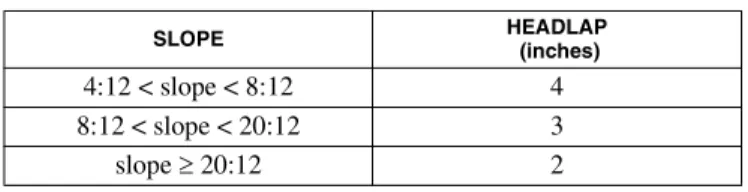
1507.7.6 Application. Minimum headlap for slate shin-gles shall be in accordance with Table 1507.7.6. Slate shingles shall be secured to the roof with two fasteners per slate.
TABLE 1507.7.6 SLATE SHINGLE HEADLAP
For SI: 1 inch = 25.4 mm.
1507.7.7 Flashing. Flashing and counterflashing shall be made with sheet metal. Valley flashing shall be a mini-mum of 15 inches (381 mm) wide. Valley and flashing metal shall be a minimum uncoated thickness of 0.0179-inch (0.455 mm) zinc-coated G90. Chimneys, stucco or brick walls shall have a minimum of two plies of felt for a cap flashing consisting of a 4-inch-wide (102 mm) strip of felt set in plastic cement and extending 1 inch (25 mm) above the first felt and a top coating of plastic cement. The felt shall extend over the base flashing 2 inches (51 mm). 1507.8 Wood shingles. The installation of wood shingles shall comply with the provisions of this section and Table 1507.8.
1507.8.1 Deck requirements. Wood shingles shall be installed on solid or spaced sheathing. Where spaced sheathing is used, sheathing boards shall not be less than 1-inch by 4-inch (25 mm by 102 mm) nominal dimensions and shall be spaced on centers equal to the weather expo-sure to coincide with the placement of fasteners.
1507.8.1.1 Solid sheathing required. Solid sheathing is required in areas where the average daily temperature in January is 25°F (-4°C) or less or where there is a possibility of ice forming along the eaves causing a backup of water.
1507.8.2 Deck slope. Wood shingles shall be installed on slopes of three units vertical in 12 units horizontal (25-per-cent slope) or greater.
1507.8.3 Underlayment. Underlayment shall comply with ASTM D 226, Type I or ASTM D 4869.
SLOPE HEADLAP (inches)
4:12 < slope < 8:12 4
8:12 < slope < 20:12 3
TABLE 1507.8
WOOD SHINGLE AND SHAKE INSTALLATION
For SI: 1 inch = 25.4 mm, °C = [(°F) - 32]/1.8.
ROOF ITEM WOOD SHINGLES WOOD SHAKES
1. Roof slope
Wood shingles shall be installed on slopes of three units vertical in 12 units horizontal (3:12) or greater.
Wood shakes shall be installed on slopes of four units vertical in 12 units horizontal (4:12) or greater.
2. Deck requirement
Temperate climate
Shingles shall be applied to roofs with solid or spaced sheathing. Where spaced sheathing is used, sheathing boards shall not be less than 1 × 4 nominal dimensions and shall be spaced on center equal to the weather exposure to coincide with the placement of fasteners.
Shakes shall be applied to roofs with solid or spaced sheathing. Where spaced sheathing is used, sheathing boards shall not be less than 1 × 4 nominal dimensions and shall be spaced on center equal to the weather exposure to coincide with the placement of fasteners. When 1 × 4 spaced sheathing is installed at 10 inches, boards must be installed between the sheathing boards.
In areas where the average daily temperature in January is 25°F or less or where there is a possibility of ice forming along the eaves causing a backup of water.
Solid sheathing required. Solid sheathing is required.
3. Interlayment No requirements. Interlayment shall comply with ASTM D 226,
Type 1.
4. Underlayment
Temperate climate Underlayment shall comply with ASTM D
226, Type 1.
Underlayment shall comply with ASTM D 226, Type 1.
In areas where there is a possibility of ice forming along the eaves causing a backup of water.
An ice barrier that consists of at least two lay-ers of underlayment cemented together or of a self-adhering polymer-modified bitumen sheet shall extend from the eave’s edge to a point at least 24 inches inside the exterior wall line of the building.
An ice barrier that consists of at least two lay-ers of underlayment cemented together or of a self-adhering polymer-modified bitumen sheet shall extend from the lowest edges of all roof surfaces to a point at least 24 inches inside the exterior wall line of the building.
5. Application
Attachment
Fasteners for wood shingles shall be hot-dipped galvanized or Type 304 (Type 316 for coastal areas) stainless steel with a minimum penetration of 0.75 inch into the sheathing. For sheathing less than 0.5 inch thick, the fasteners shall extend through the sheathing.
Fasteners for wood shakes shall be hot-dipped galvanized or Type 304 (Type 316 for coastal areas) with a minimum penetration of 0.75 inch into the sheathing. For sheathing less than 0.5 inch thick, the fasteners shall extend through the sheathing.
No. of fasteners Two per shingle. Two per shake.
Exposure Weather exposures shall not exceed those set
forth in Table 1507.8.7.
Weather exposures shall not exceed those set forth in Table 1507.9.8.
Method
Shingles shall be laid with a side lap of not less than 1.5 inches between joints in courses, and no two joints in any three adjacent courses shall be in direct alignment. Spacing between shingles shall be 0.25 to 0.375 inch.
Shakes shall be laid with a side lap of not less than 1.5 inches between joints in adjacent courses. Spacing between shakes shall not be less than 0.375 inch or more than 0.625 inch for shakes and taper sawn shakes of naturally durable wood and shall be 0.25 to 0.375 inch for preservative-treated taper sawn shakes.
1507.8.3.1 Underlayment and high wind. Underlay-ment applied in areas subject to high winds [Vasd greater
than 110 mph (49 m/s) as determined in accordance with Section 1609.3.1] shall be applied with corrosion-resistant fasteners in accordance with the manufac-turer’s installation instructions. Fasteners are to be applied along the overlap not farther apart than 36 inches (914 mm) on center.
Underlayment installed where Vasd, in accordance
with Section 1609.3.1, equals or exceeds 120 mph (54 m/s) shall comply with ASTM D 226 Type II or ASTM D 4869 Type IV. The underlayment shall be attached in a grid pattern of 12 inches (305 mm) between side laps with a 6-inch (152 mm) spacing at the side laps. Underlayment shall be applied in accordance with the manufacturer’s installation instructions except all laps shall be a minimum of 4 inches (102 mm). Underlay-ment shall be attached using metal or plastic cap nails with a head diameter of not less than 1 inch (25 mm) with a thickness of at least 32-gauge [0.0134 inch (0.34 mm)] sheet metal. The cap nail shank shall be a mini-mum of 12 gauge [0.105 inch (2.67 mm)] with a length to penetrate through the roof sheathing or a minimum of 3/
4 inch (19.1 mm) into the roof sheathing.
Exception: As an alternative, adhered underlayment complying with ASTM D 1970 shall be permitted. 1507.8.4 Ice barrier. In areas where there has been a his-tory of ice forming along the eaves causing a backup of water, an ice barrier that consists of at least two layers of underlayment cemented together or of a self-adhering polymer-modified bitumen sheet shall be used in lieu of normal underlayment and extend from the lowest edges of all roof surfaces to a point at least 24 inches (610 mm) inside the exterior wall line of the building.
Exception: Detached accessory structures that contain no conditioned floor area.
1507.8.5 Material standards. Wood shingles shall be of naturally durable wood and comply with the requirements of Table 1507.8.5.
TABLE 1507.8.5
WOOD SHINGLE MATERIAL REQUIREMENTS
CSSB = Cedar Shake and Shingle Bureau
1507.8.6 Attachment. Fasteners for wood shingles shall be corrosion resistant with a minimum penetration of 3
/4
inch (19.1 mm) into the sheathing. For sheathing less than
1
/2 inch (12.7 mm) in thickness, the fasteners shall extend
through the sheathing. Each shingle shall be attached with a minimum of two fasteners.
1507.8.7 Application. Wood shingles shall be laid with a side lap not less than 11
/2 inches (38 mm) between joints in
adjacent courses, and not be in direct alignment in alter-nate courses. Spacing between shingles shall be 1
/4 to 3
/8
inches (6.4 to 9.5 mm). Weather exposure for wood shin-gles shall not exceed that set in Table 1507.8.7.
TABLE 1507.8.7
WOOD SHINGLE WEATHER EXPOSURE AND ROOF SLOPE
For SI: 1 inch = 25.4 mm.
1507.8.8 Flashing. At the juncture of the roof and vertical surfaces, flashing and counterflashing shall be provided in accordance with the manufacturer’s installation instruc-tions, and where of metal, shall not be less than 0.019-inch (0.48 mm) (No. 26 galvanized sheet gage) corrosion-resis-tant metal. The valley flashing shall extend at least 11 inches (279 mm) from the centerline each way and have a splash diverter rib not less than 1 inch (25 mm) high at the flow line formed as part of the flashing. Sections of flash-ing shall have an end lap of not less than 4 inches (102 mm). For roof slopes of three units vertical in 12 units hor-izontal (25-percent slope) and over, the valley flashing shall have a 36-inch-wide (914 mm) underlayment of either one layer of Type I underlayment running the full length of the valley or a self-adhering polymer-modified bitumen sheet complying with ASTM D 1970, in addition to other required underlayment. In areas where the average daily temperature in January is 25°F (-4°C) or less or where there is a possibility of ice forming along the eaves causing a backup of water, the metal valley flashing underlayment shall be solidly cemented to the roofing underlayment for slopes under seven units vertical in 12 units horizontal (58-percent slope) or self-adhering poly-mer-modified bitumen sheet shall be installed.
1507.9 Wood shakes. The installation of wood shakes shall comply with the provisions of this section and Table 1507.8.
1507.9.1 Deck requirements. Wood shakes shall only be used on solid or spaced sheathing. Where spaced
sheath-MATERIAL APPLICABLE MINIMUM GRADES
GRADING RULES
Wood shingles of naturally
durable wood 1, 2 or 3 CSSB
ROOFING MATERIAL LENGTH
(inches) GRADE
EXPOSURE (inches) 3:12 pitch
to < 4:12
4:12 pitch or steeper
Shingles of naturally durable wood
16
No. 1 No. 2 No. 3
3.75 3.5
3
5 4 3.5 18
No. 1 No. 2 No. 3
4.25 4 3.5
5.5 4.5 4 24
No. 1 No. 2 No. 3
5.75 5.5
5
7.5 6.5 5.5
ing is used, sheathing boards shall not be less than 1-inch by 4-inch (25 mm by 102 mm) nominal dimensions and shall be spaced on centers equal to the weather exposure to coincide with the placement of fasteners. Where 1-inch by 4-inch (25 mm by 102 mm) spaced sheathing is installed at 10 inches (254 mm) o.c., additional 1-inch by 4-inch (25 mm by 102 mm) boards shall be installed between the sheathing boards.
1507.9.1.1 Solid sheathing required. Solid sheathing is required in areas where the average daily temperature in January is 25°F (-4°C) or less or where there is a possibility of ice forming along the eaves causing a backup of water.
1507.9.2 Deck slope. Wood shakes shall only be used on slopes of four units vertical in 12 units horizontal (33-per-cent slope) or greater.
1507.9.3 Underlayment. Underlayment shall comply with ASTM D 226, Type I or ASTM D 4869.
1507.9.3.1 Underlayment and high wind. Underlay-ment applied in areas subject to high winds [Vasd greater
than 110 mph (49 m/s) as determined in accordance with Section 1609.3.1] shall be applied with corrosion-resistant fasteners in accordance with the manufac-turer’s installation instructions. Fasteners are to be applied along the overlap not farther apart than 36 inches (914 mm) on center.
Underlayment installed where Vasd, in accordance
with Section 1609.3.1, equals or exceeds 120 mph (54 m/s) shall comply with ASTM D 226 Type II or ASTM D 4869 Type IV. The underlayment shall be attached in a grid pattern of 12 inches (305 mm) between side laps with a 6-inch (152 mm) spacing at the side laps. Underlayment shall be applied in accordance with the manufacturer’s installation instructions except all laps shall be a minimum of 4 inches (102 mm). Underlay-ment shall be attached using metal or plastic cap nails with a head diameter of not less than 1 inch (25 mm) with a thickness of at least 32-gauge [0.0134 inch (0.34 mm)] sheet metal. The cap nail shank shall be a
mini-mum of 12 gauge [0.105 inch (2.67 mm)] with a length to penetrate through the roof sheathing or a minimum of 3/
4 inch (19.1 mm) into the roof sheathing.
Exception: As an alternative, adhered underlayment complying with ASTM D 1970 shall be permitted. 1507.9.4 Ice barrier. In areas where there has been a his-tory of ice forming along the eaves causing a backup of water, an ice barrier that consists of at least two layers of underlayment cemented together or of a self-adhering polymer-modified bitumen sheet shall be used in lieu of normal underlayment and extend from the lowest edges of all roof surfaces to a point at least 24 inches (610 mm) inside the exterior wall line of the building.
Exception: Detached accessory structures that contain no conditioned floor area.
1507.9.5 Interlayment. Interlayment shall comply with ASTM D 226, Type I.
1507.9.6 Material standards. Wood shakes shall comply with the requirements of Table 1507.9.6.
TABLE 1507.9.6
WOOD SHAKE MATERIAL REQUIREMENTS
CSSB = Cedar Shake and Shingle Bureau.
TFS = Forest Products Laboratory of the Texas Forest Services.
MATERIAL MINIMUM GRADES
APPLICABLE GRADING
RULES
Wood shakes of naturally durable wood 1 CSSB
Taper sawn shakes of naturally durable
wood 1 or 2 CSSB
Preservative-treated shakes and shingles of
naturally durable wood 1 CSSB
Fire-retardant-treated shakes and shingles
of naturally durable wood 1 CSSB
Preservative-treated taper sawn shakes of Southern pine treated in accordance with AWPA U1 (Commodity Specification A, Use Category 3B and Section 5.6)
1 or 2 TFS
TABLE 1507.9.8
WOOD SHAKE WEATHER EXPOSURE AND ROOF SLOPE
For SI: 1 inch = 25.4 mm.
a. For 24-inch by 0.375-inch handsplit shakes, the maximum exposure is 7.5 inches.
ROOFING MATERIAL LENGTH
(inches) GRADE
EXPOSURE (inches) 4:12 PITCH OR STEEPER
Shakes of naturally durable wood 18
24
No. 1 No. 1
7.5 10a
Preservative-treated taper sawn shakes of Southern yellow pine
18 24
No. 1 No. 1
7.5 10 18
24
No. 2 No. 2
5.5 7.5
Taper sawn shakes of naturally durable wood
18 24
No. 1 No. 1
7.5 10 18
24
No. 2 No. 2
5.5 7.5
1507.9.7 Attachment. Fasteners for wood shakes shall be corrosion resistant with a minimum penetration of 3
/4 inch
(19.1 mm) into the sheathing. For sheathing less than 1/ 2
inch (12.7 mm) in thickness, the fasteners shall extend through the sheathing. Each shake shall be attached with a minimum of two fasteners.
1507.9.8 Application. Wood shakes shall be laid with a side lap not less than 11
/2 inches (38 mm) between joints in
adjacent courses. Spacing between shakes in the same course shall be 3
/8 to 5
/8 inches (9.5 to 15.9 mm) for shakes
and taper sawn shakes of naturally durable wood and shall be 1
/4 to 3
/8 inch (6.4 to 9.5 mm) for preservative taper
sawn shakes. Weather exposure for wood shakes shall not exceed those set in Table 1507.9.8.
1507.9.9 Flashing. At the juncture of the roof and vertical surfaces, flashing and counterflashing shall be provided in accordance with the manufacturer’s installation instruc-tions, and where of metal, shall not be less than 0.019-inch (0.48 mm) (No. 26 galvanized sheet gage) corrosion-resis-tant metal. The valley flashing shall extend at least 11 inches (279 mm) from the centerline each way and have a splash diverter rib not less than 1 inch (25 mm) high at the flow line formed as part of the flashing. Sections of flash-ing shall have an end lap of not less than 4 inches (102 mm). For roof slopes of three units vertical in 12 units hor-izontal (25-percent slope) and over, the valley flashing shall have a 36-inch-wide (914 mm) underlayment of either one layer of Type I underlayment running the full length of the valley or a self-adhering polymer-modified bitumen sheet complying with ASTM D 1970, in addition to other required underlayment. In areas where the average daily temperature in January is 25°F (-4°C) or less or where there is a possibility of ice forming along the eaves causing a backup of water, the metal valley flashing underlayment shall be solidly cemented to the roofing underlayment for slopes under seven units vertical in 12 units horizontal (58-percent slope) or self-adhering poly-mer-modified bitumen sheet shall be installed.
1507.10 Built-up roofs. The installation of built-up roofs shall comply with the provisions of this section.
1507.10.1 Slope. Built-up roofs shall have a design slope of a minimum of one-fourth unit vertical in 12 units hori-zontal (2-percent slope) for drainage, except for coal-tar built-up roofs that shall have a design slope of a minimum one-eighth unit vertical in 12 units horizontal (1-percent slope).
1507.10.2 Material standards. Built-up roof covering materials shall comply with the standards in Table 1507.10.2 or UL 55A.
TABLE 1507.10.2
BUILT-UP ROOFING MATERIAL STANDARDS
1507.11 Modified bitumen roofing. The installation of mod-ified bitumen roofing shall comply with the provisions of this section.
1507.11.1 Slope. Modified bitumen membrane roofs shall have a design slope of a minimum of one-fourth unit verti-cal in 12 units horizontal (2-percent slope) for drainage. 1507.11.2 Material standards. Modified bitumen roof coverings shall comply with CGSB 37-GP-56M, ASTM D 6162, ASTM D 6163, ASTM D 6164, ASTM D 6222, ASTM D 6223, ASTM D 6298 or ASTM D 6509. 1507.12 Thermoset single-ply roofing. The installation of thermoset single-ply roofing shall comply with the provisions of this section.
1507.12.1 Slope. Thermoset single-ply membrane roofs shall have a design slope of a minimum of one-fourth unit
MATERIAL STANDARD STANDARD
Acrylic coatings used in roofing ASTM D 6083
Aggregate surfacing ASTM D 1863
Asphalt adhesive used in roofing ASTM D 3747
Asphalt cements used in roofing ASTM D 3019; D 2822;
D 4586 Asphalt-coated glass fiber base sheet ASTM D 4601
Asphalt coatings used in roofing ASTM D 1227; D 2823;
D 2824; D 4479
Asphalt glass felt ASTM D 2178
Asphalt primer used in roofing ASTM D 41
Asphalt-saturated and asphalt-coated
organic felt base sheet ASTM D 2626
Asphalt-saturated organic felt
(perfo-rated) ASTM D 226
Asphalt used in roofing ASTM D 312
Coal-tar cements used in roofing ASTM D 4022; D 5643
Coal-tar saturated organic felt ASTM D 227
Coal-tar pitch used in roofing ASTM D 450; Type I or II
Coal-tar primer used in roofing,
dampproofing and waterproofing ASTM D 43
Glass mat, coal tar ASTM D 4990
Glass mat, venting type ASTM D 4897
Mineral-surfaced inorganic cap sheet ASTM D 3909 Thermoplastic fabrics used in roofing ASTM D 5665, D 5726
vertical in 12 units horizontal (2-percent slope) for drain-age.
1507.12.2 Material standards. Thermoset single-ply roof coverings shall comply with ASTM D 4637, ASTM D 5019 or CGSB 37-GP-52M.
1507.12.3 Ballasted thermoset low-slope roofs. Bal-lasted thermoset low-slope roofs (roof slope < 2:12) shall be installed in accordance with this section and Section 1504.4. Stone used as ballast shall comply with ASTM D 448.
1507.13 Thermoplastic single-ply roofing. The installation of thermoplastic single-ply roofing shall comply with the provisions of this section.
1507.13.1 Slope. Thermoplastic single-ply membrane roofs shall have a design slope of a minimum of one-fourth unit vertical in 12 units horizontal (2-percent slope).
1507.13.2 Material standards. Thermoplastic single-ply roof coverings shall comply with ASTM D 4434, ASTM D 6754, ASTM D 6878 or CGSB CAN/CGSB 37-54. 1507.13.3 Ballasted thermoplastic low-slope roofs. Bal-lasted thermoplastic low-slope roofs (roof slope < 2:12) shall be installed in accordance with this section and Sec-tion 1504.4. Stone used as ballast shall comply with ASTM D448.
1507.14 Sprayed polyurethane foam roofing. The installa-tion of sprayed polyurethane foam roofing shall comply with the provisions of this section.
1507.14.1 Slope. Sprayed polyurethane foam roofs shall have a design slope of a minimum of one-fourth unit verti-cal in 12 units horizontal (2-percent slope) for drainage. 1507.14.2 Material standards. Spray-applied polyure-thane foam insulation shall comply with Type III or IV as defined in ASTM C 1029.
1507.14.3 Application. Foamed-in-place roof insulation shall be installed in accordance with the manufacturer's instructions. A liquid-applied protective coating that com-plies with Table 1507.14.3 shall be applied no less than 2 hours nor more than 72 hours following the application of the foam.
TABLE 1507.14.3
PROTECTIVE COATING MATERIAL STANDARDS
1507.14.4 Foam plastics. Foam plastic materials and installation shall comply with Chapter 26.
1507.15 Liquid-applied roofing. The installation of liquid-applied roofing shall comply with the provisions of this sec-tion.
1507.15.1 Slope. Liquid-applied roofing shall have a design slope of a minimum of one-fourth unit vertical in 12 units horizontal (2-percent slope).
1507.15.2 Material standards. Liquid-applied roofing shall comply with ASTM C 836, ASTM C 957, ASTM D 1227 or ASTM D 3468, ASTM D 6083, ASTM D 6694 or ASTM D 6947.
1507.16 Roof gardens and landscaped roofs. Roof gardens and landscaped roofs shall comply with the requirements of this chapter and Sections 1607.12.3 and 1607.12.3.1 and the
Fire Code.
1507.16.1 Structural fire resistance. The structural frame and roof construction supporting the load imposed upon the roof by the roof gardens or landscaped roofs shall comply with the requirements of Table 601.
1507.17 Photovoltaic modules/shingles. The installation of photovoltaic modules/shingles shall comply with the provi-sions of this section.
1507.17.1 Material standards. Photovoltaic modules/ shingles shall be listed and labeled in accordance with UL 1703.
1507.17.2 Attachment. Photovoltaic modules/shingles shall be attached in accordance with the manufacturer’s installation instructions.
1507.17.3 Wind resistance. Photovoltaic modules/shin-gles shall be tested in accordance with procedures and acceptance criteria in ASTM D 3161. Photovoltaic mod-ules/shingles shall comply with the classification require-ments of Table 1507.2.7.1(2) for the appropriate maximum nominal design wind speed. Photovoltaic mod-ules/shingle packaging shall bear a label to indicate com-pliance with the procedures in ASTM D 3161 and the required classification from Table 1507.2.7.1(2).
1507.18 Hot-applied rubberized-asphalt roofing. The installation of hot-applied rubberized-asphalt roofing shall comply with the provisions of this section.
1507.18.1 Slope. Hot-applied rubberized-asphalt roof membranes shall not be required to have a minimum design slope (0-percent slope).
1507.18.2 Material standards. Hot-applied rubberized-asphalt roofing shall be one-part hot-applied rubberized asphalt and comply with CAN/CGSB-37.50-M89. 1507.18.3 Protected membrane ballasted low-slope roofs. Protected membrane ballasted roof assemblies with a low-slope (roof slope < 2:12) shall be installed in accor-dance with this section and Section 1504.4. Stone used as ballast shall comply with ASTM D448.
SECTION 1508 ROOF INSULATION
1508.1 General. The use of above-deck thermal insulation shall be permitted provided such insulation is covered with an approved roof covering and passes the tests of FM 4450 or UL 1256 when tested as an assembly.
Exceptions:
1. Foam plastic roof insulation shall conform to the material and installation requirements of Chapter 26.
MATERIAL STANDARD
Acrylic coating ASTM D 6083
Silicone coating ASTM D 6694