Camera Browser Interface
NDN-5000, NDI-5000, NIN-5000, NII-5000, NTI-5000
Table of Contents
1 Browser connection 11
1.1 System requirements 11
1.2 Establishing the connection 12
1.2.1 Password protection in camera 12
1.3 Protected network 12
2 System Overview 13
2.1 Livepage 13
2.2 Recordings 13
2.3 Settings 13
3 Operation via the browser 14
3.1 Livepage 14
3.1.1 Image selection 14
3.1.2 Status icons 15
3.1.3 Cameras with PTZ control 16
3.1.4 View Control ROI 17
3.1.5 Cameras with alarm I/O 18
3.1.6 System Log / Event Log 19
3.1.7 Saving snapshots 19
3.1.8 Recording video sequences 19
3.1.9 Running recording program 20
3.1.10 Audio communication 20
3.1.11 Processor load 20
3.2 Playback page 21
3.2.1 Selecting recordings for playback 21
3.2.2 Exporting tracks 22
3.2.3 Searching for tracks 22
3.2.4 Controlling playback 23
4 Settings Overview 25
4.1 Configuration Menu 25
4 en | Table of Contents Camera Browser Interface
5 Basic Mode 27
5.1 Device Access 27
5.1.1 Naming 27
5.1.2 Password 27
5.2 Date/Time 29
5.2.1 Device date, time and zone 29
5.2.2 Time server IP address 29
5.2.3 Time server type 29
5.3 Network 30
5.4 Encoder 31
5.5 Audio 31
5.6 Recording 31
5.7 System Overview 31
6 Advanced General Settings 32
6.1 Identification 32
6.1.1 Naming 32
6.1.2 ID 32
6.1.3 Initiator extension 32
6.2 Password 33
6.2.1 Password 33
6.2.2 Confirm password 33
6.3 Date/Time 34
6.3.1 Date format 34
6.3.2 Device date / Device time 34
6.3.3 Device time zone 34
6.3.4 Daylight saving time 34
6.3.5 Time server IP address 35
6.3.6 Time server type 35
7 Web Interface 38
7.1 Appearance 38
7.1.1 Website language 38
7.1.2 Company logo 38
7.1.3 Device logo 38
7.1.4 Show VCA metadata 38
7.1.5 Show overlay icons 38
7.1.6 Select Video player 39
7.1.7 JPEG size, interval and quality 39
7.2 LIVEPAGE Functions 40
7.2.1 Transmit audio 40
7.2.2 Lease time [s] 40
7.2.3 Show alarm inputs 40
7.2.4 Show alarm outputs 40
7.2.5 Show event log 40
7.2.6 Show system log 41
7.2.7 Allow snapshots 41
7.2.8 Allow local recording 41
7.2.9 I-frames-only stream 41
7.2.10 Path for JPEG and video files 41
7.3 Logging 42
7.3.1 Save event log 42
7.3.2 Save system log 42
8 Camera 43
8.1 Installer Menu 43
8.1.1 Base frame rate 43
8.1.2 Camera LED 43
8.1.3 Mirror image 43
8.1.4 Flip image 43
8.1.5 Reboot device 43
8.1.6 Factory defaults 43
8.2 Picture Settings — User Mode 44
8.2.1 Current mode 44
6 en | Table of Contents Camera Browser Interface
8.3 Picture Settings — Color 46
8.3.1 White balance 46
8.4 Picture Settings — ALC 47
8.4.1 Exposure/frame rate 47
8.4.2 Day/night 47
8.5 Picture Settings — Enhance 49
8.5.1 Sharpness level 49
8.5.2 Backlight compensation 49
8.5.3 Contrast enhancement 49
8.5.4 Intelligent DNR 49
8.5.5 Temporal noise filtering 49
8.5.6 Spatial noise filtering 49
8.6 Encoder Settings 50
8.7 Privacy Masks 51
8.8 Audio 51
8.9 Pixel Counter 51
9 Encoder Settings 52
9.1 Encoder Profile 53
9.1.1 Pre-defined profiles 53
9.1.2 Changing a profile 53
9.1.3 Profile name 54
9.1.4 Target bit rate 54
9.1.5 Maximum bit rate 54
9.1.6 Encoding interval 54
9.1.7 Standard definition video resolution 54
9.1.8 Expert Settings 54
9.1.9 Default 56
9.2 Encoder Streams 57
10.1.2 Recording media 61 10.1.3 Activating and configuring storage media 63
10.1.4 Formatting storage media 63
10.1.5 Deactivating storage media 63
10.2 Recording Profiles 65
10.2.1 Recording track selection 66
10.2.2 Standard recording 66
10.2.3 Alarm recording 67
10.3 Maximum Retention Time 67
10.4 Recording Scheduler 68
10.4.1 Weekdays 68
10.4.2 Holidays 68
10.4.3 Profile names 69
10.4.4 Activate recording 69
10.4.5 Recording status 69
10.5 Recording Status 70
11 Alarm 71
11.1 Alarm Connections 71
11.1.1 Connect on alarm 71
11.1.2 Number of destination IP address 71
11.1.3 Destination IP address 71
11.1.4 Destination password 71
11.1.5 Video transmission 72
11.1.6 Stream 72
11.1.7 Remote port 72
11.1.8 Video output 72
11.1.9 Decoder 72
11.1.10 SSL encryption 73
11.1.11 Auto-connect 73
11.1.12 Audio 73
11.2 Video Content Analyses (VCA) 74
11.3 Audio Alarm 75
11.3.1 Audio alarm 75
11.3.2 Name 75
8 en | Table of Contents Camera Browser Interface
11.3.5 Sensitivity 75
11.4 Alarm E-Mail 76
11.4.1 Send alarm e-mail 76
11.4.2 Mail server IP address 76
11.4.3 SMTP user name 76
11.4.4 SMTP password 76
11.4.5 Format 76
11.4.6 Image size 76
11.4.7 Attach JPEG from camera 77
11.4.8 Destination address 77
11.4.9 Sender address 77
11.4.10 Test e-mail 77
11.5 Alarm Task Editor 78
12 Setting up VCA 79
12.1 VCA - Silent VCA 79
12.2 VCA - Profiles 80
12.2.1 Aggregation time [s] 80
12.2.2 Analysis type 80
12.2.3 Motion detector 81
12.2.4 Tamper detection 82
12.3 VCA - Scheduled 86
12.3.1 Weekdays 86
12.3.2 Holidays 86
12.4 VCA - Event triggered 88
12.4.1 Trigger 88
12.4.2 Trigger active 88
12.4.3 Trigger inactive 88
13.2.4 Output name 89
13.2.5 Trigger output 89
14 Network 90
14.1 Network Access 90
14.1.1 Automatic IP assignment 90
14.1.2 IP V4 address 90
14.1.3 IP V6 address 91
14.1.4 DNS server address 1 91
14.1.5 Video transmission 91
14.1.6 TCP rate control 91
14.1.7 HTTP browser port 91
14.1.8 HTTPS browser port 92
14.1.9 RCP+ port 1756 92
14.1.10 Telnet support 92
14.1.11 Interface mode ETH 92
14.1.12 Network MSS [Byte] 92
14.1.13 iSCSI MSS [Byte] 93
14.1.14 Network MTU [Byte] 93
14.1.15 Enable DynDNS 93
14.1.16 Provider 93
14.1.17 Host name 93
14.1.18 User name 93
14.1.19 Password 93
14.1.20 Force registration now 93
14.1.21 Status 94
14.2 Advanced 95
14.2.1 SNMP 95
14.2.2 Authentication (802.1x) 96
14.2.3 RTSP port 96
14.2.4 UPnP 96
14.2.5 TCP metadata input 96
14.2.6 Quality of service 96
14.2.7 Cloud-based services 97
14.3 Multicast 98
10 en | Table of Contents Camera Browser Interface
14.3.3 Port 99
14.3.4 Streaming 99
14.3.5 Multicast packet TTL 99
14.4 Image Posting 100
14.4.1 JPEG 100
14.5 Accounts 101
14.6 IP V4 filter 102
15 Service 103
15.1 Maintenance 103
15.1.1 Update server 103
15.1.2 Firmware 103
15.1.3 Upload history 104
15.1.4 Configuration 104
15.1.5 SSL certificate 104
15.1.6 Maintenance log 105
1
Browser connection
A computer with Microsoft Internet Explorer is used to receive live images from the camera, control the camera, and replay stored sequences. The camera is configured over the network using the browser.
1.1
System requirements
– Network access (Intranet or Internet)
– Microsoft Internet Explorer version 9 (32-bit only) – Screen resolution at least 1024 × 768 pixels – 16- or 32-bit color depth
– JVM installed
The Web browser must be configured to enable Cookies from the IP address of the unit.
In Windows Vista, deactivate protected mode on the Security tab under Internet Options.
To play back live video images, an appropriate ActiveX must be installed on the computer. If necessary, install the Bosch Video Client.
12 en | Browser connection Camera Browser Interface
1.2
Establishing the connection
The camera must have a valid IP address and a compatible subnet mask to operate on your network. By default, DHCP is pre-set at the factory to ON and so your DHCP server assigns an IP address. With no DHCP server the default address is
192.168.0.1
1. Start the Web browser.
2. Enter the IP address of the camera as the URL.
3. During initial installation, confirm any security questions that appear.
Note:
If you do not connect, the camera may have reached its maximum number of connections. Depending on the device and network configuration, each camera can have up to 25 web browser connections, or up to 50 connections via Bosch Video Client or Bosch Video Management System.
1.2.1
Password protection in camera
A camera offers the option of limiting access across various authorization levels. If the camera is password-protected, a message to enter the password appears.
1. Enter the user name and the associated password in the appropriate fields.
2. Click OK. If the password is correct, the desired page is displayed.
1.3
Protected network
If a RADIUS server is used for network access control (802.1x authentication), the camera must be configured first. To
2
System Overview
When a connection is established, the Livepage is initially displayed. The application title bar displays three items: LIVEPAGE, PLAYBACK, SETTINGS.
Note:
The PLAYBACK link is only visible if a storage medium has been configured for recording. (With VRM recording this option is not active.)
2.1
Livepage
The LIVEPAGE is used to display the live video stream and control the camera.
2.2
Recordings
The PLAYBACK page is used for playing back recorded sequences.
2.3
Settings
The SETTINGS page is used to configure the camera and the application interface.
14 en | Operation via the browser Camera Browser Interface
3
Operation via the browser
3.1
Livepage
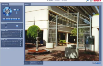
After the connection is established, the Livepage is initially displayed. It shows the live video image on the right of the browser window. Depending on the configuration, various text overlays may be visible on the live video image.
Other information may also be shown next to the live video image. The items shown depend on the settings on the LIVEPAGE Functions page.
Figure 3.1 Livepage
3.1.1
Image selection
3.1.2
Status icons
Various overlays in the video image provide important status information. The overlays provide the following information:
Decoding error
The frame might show artefacts due to decoding errors. If other frames reference this frame, they might also show decoding errors but won’t be marked with the icon.
Alarm flag
Shown on a media item to indicate an alarm.
Communication error
A communication error, such as a connection failure to the storage medium, a protocol violation or a timeout, is indicated by this icon. An automatic reconnection procedure is started in the background to recover from this error.
Gap
Indicates a gap in the recorded video.
Watermark flag
Watermark is set on media item.
Invalid watermark flag
16 en | Operation via the browser Camera Browser Interface
Motion flag
Indicates that motion is dectected.
Storage discovery
Indicates that recorded video is being retrieved.
3.1.3
Cameras with PTZ control
For cameras where PTZ control is possible, the View Control panel is activated.
Pan and tilt
To control the pan and tilt of PTZ cameras:
Click and hold the up or down arrows to tilt.
Click and hold the left or right arrows to pan.
Click and hold the center area to control both.
Move the mouse cursor over the video image; additional options for controlling peripherals are displayed with the mouse cursor. Zoom, focus, and iris
To control the zoom, focus, and iris of PTZ cameras: 1. Click and hold to zoom out; click and hold
Pre-position
To move the camera to a pre-position, click one of the buttons numbered one to six.
To store the current position of the camera in a pre-position: 1. Position the camera.
2. Enter a pre-position number. 3. Click Set.
3.1.4
View Control ROI
(not for SD cameras)
When the stream 2 encoder stream is set for Region of Interest (ROI), a specific type of View Control panel is activated.
Refer to Section 9.2.1 H.264 settings, page 57 for more information on setting up stream 2. (If dual ROI is available, open the camera in a second browser window to set up the second ROI on stream 2.)
Zoom
To zoom in on a region of the stream 2 image:
Click and hold to zoom in; click and hold to zoom out.
Click to see the full image. Select an area
To select a particular region of the image:
1. Click and hold the arrows to move up and down, and from side to side through the image.
18 en | Operation via the browser Camera Browser Interface
Set positions
To store the current view: 1. Select a region of interest. 2. Click Set.
3. Click a number.
To display a pre-set region of interest, click one of the buttons numbered one to six.
3.1.5
Cameras with alarm I/O
(only for cameras with I/O connections)
The alarm input and output are displayed in the Digital I/O panel next to the camera image.
The alarm symbol is for information and indicates the input status of the alarm input:
– Active 1 = Symbol lights – Active 0 = Symbol not lit.
The camera alarm output allows the operation of an external device (for example, a light or a door opener).
To operate, click the relay symbol.
3.1.6
System Log / Event Log
The System Log field contains information about the operating status of the camera and the connection.
Events such as the triggering or the end of alarms are shown in the Event Log field.
To view, filter and save these messages to a file, click in the top right-hand corner.
To clear the log, click in the top right-hand corner of the relevant field.
3.1.7
Saving snapshots
Individual images from the video sequence that is currently being shown on the Livepage can be saved in JPEG format on the computer's hard drive.
Click the camera icon to save a single image. – The storage location depends on the configuration of
the camera.
3.1.8
Recording video sequences
Sections of the video sequence that is currently being shown on the Livepage can be saved on the computer's hard drive. The sequences are recorded at the resolution specified in the encoder configuration. The storage location depends on the configuration of the camera.
1. Click the recording icon to record video sequences. – Saving begins immediately. The red dot on the icon
indicates that a recording is in progress. 2. Click the recording icon again to stop recording. Play back saved video sequences using the Player from Bosch Security Systems.
20 en | Operation via the browser Camera Browser Interface
3.1.9
Running recording program
The hard drive icon below the camera images on the Livepage changes during an automatic recording.
The icon lights up and displays a moving graphic to indicate a running recording. If no recording is taking place, a static icon is displayed.
3.1.10
Audio communication
(only for cameras with audio)
Audio can be sent and received via the Livepage if the active monitor and the remote station of the camera support audio. 1. Press and hold the F12 key on the keyboard to send an
audio signal to the camera.
2. Release the key to stop sending audio.
All connected users receive audio signals sent from the camera but only the user who first pressed the F12 key can send audio signals; others must wait for the first user to release the key.
3.1.11
Processor load
When accessing the camera with a browser, the processor load and network information is available in the upper right of the window next to the Bosch logo.
Move the mouse cursor over the icons to display numerical values. This information can help with problem solving or when fine tuning the device.
3.2
Playback page
Click PLAYBACK to access the Playback page from the Livepage or Settings page. The Playback link is only visible if a direct iSCSI or SD card has been configured for recording. (With VRM recording this option is not active.)
A collapsible panel on the left of the display has four tabs: – Track list
– Export – Search – Search results
Select Recording 1 or 2 from the drop-down menu at the top of the window.
3.2.1
Selecting recordings for playback
To see all saved sequences: 1. Click the track list tab .
A list of tracks with a number assigned to each sequence is displayed. Start time and stop time, recording duration, number of alarms, and recording type are shown for each track.
2. At the bottom of the window, select the maximum number of tracks to be displayed in the list.
3. Use the arrow buttons at the bottom to browse the list. 4. To view tracks beginning from a particular time, enter the
time code and click Get Tracks.
5. Click a track. The playback for the selected sequence starts.
22 en | Operation via the browser Camera Browser Interface
3.2.2
Exporting tracks
1. Select a track in the track list. 2. Click the export tab .
3. The start and stop time are filled-in for the selected track. If required, change the times.
4. Select a target.
5. Select the original or a condensed speed. 6. Click the save icon .
Note:
The target server address is set on the Network / Accounts page.
3.2.3
Searching for tracks
1. Click the search tab .
2. Select a search mode; Any motion, Field, Line crossing, Recorded alarms, or Best faces.
3. To limit the search to a particular time range, enter the start and stop times.
4. Click Start Search.
The results are shown in the search results tab . 5. Click a result to play it back.
3.2.4
Controlling playback
Time bar
The time bar below the video image allows quick orientation. The time interval associated with the sequence is displayed in the bar in gray. A green arrow above the bar indicates the position of the image currently being played back within the sequence.
The time bar offers various options for navigation in and between sequences.
– Change the time interval displayed by clicking the plus or minus icons. The display can span a range from two months to a few seconds.
– If required, drag the green arrow to the point in time at which the playback should begin.
– Red bars indicate the points in time where alarms were triggered. Drag the green arrow to navigate to these points quickly.
Controls
Use the jog dial to quickly scan the sequences. The time code is displayed above it. The buttons have the following functions:
Start/Pause playback
Select the playback speed using the speed regulator .
24 en | Operation via the browser Camera Browser Interface
Jump to start of active sequence or to previous sequence Jump to start of the next video sequence in the list Bookmarks
You can set markers in a sequence and jump to these directly. These bookmarks are indicated as small yellow arrows above the time interval. Use the bookmarks as follows:
Jump to the previous bookmark Set bookmark
Jump to the following bookmark
Bookmarks are only valid while in the Recordings page; they are not saved with the sequences. All bookmarks are deleted when you leave the page.
4
Settings Overview
4.1
Configuration Menu
The settings page provides access to the configuration menu which contains all the unit's parameters arranged in groups. There are two options for configuring the unit or checking the current settings:
– Basic Mode – Advanced Mode
In Basic Mode the most important parameters are arranged in seven groups. This allows you to change the basic settings with just a few entries and then put the device into operation. Advanced Mode is recommended only for expert users or system support personnel. You can access all device
parameters in this mode. Settings that affect the fundamental functionality of the device (such as firmware updates) can only be changed in this mode.
26 en | Settings Overview Camera Browser Interface
4.2
Settings
Navigation
To view the current settings:
1. Click the Basic Mode menu or the Advanced Mode menu to expand it.
2. For the Advanced Mode menu, click a menu sub-heading to expand it.
3. Click a sub-menu. The corresponding page is opened.
Making Changes
You can change the settings by entering new values or by selecting a predefined value from a list field.
Note:
When entering names do not use any special characters, for example &. Special characters are not supported by the internal recording management system.
Saving changes
After making changes in a window, click Set to send the new settings to the device and save them there.
Clicking Set saves only the settings in the current window. Changes in any other windows are ignored.
Click SETTINGS in the applications title bar to close the window without saving the changes made.
Note:
5
Basic Mode
5.1
Device Access
5.1.1
Naming
Enter a unique name to assist in identification. This name simplifies the management of multiple devices in more extensive systems.
The name is used for remote identification, for example, in the event of an alarm. Choose a name that makes it as easy as possible to identify the location unambiguously.
5.1.2
Password
A password prevents unauthorized access to the device. The device has three authorization levels: service, user, and live. – service is the highest authorization level. Entering the
correct password gives access to all the functions of the camera and allows all configuration settings to be changed.
– user is the middle authorization level. This user can operate the device, play back recordings, and also control a camera but cannot change the configuration.
– live is the lowest authorization level. It can only be used to view the live video image and switch between the different live image displays.
You can define and change a password for each authorization level if you are logged in as service or if the camera is not password protected.
Use the various authorization levels to limit access. Proper password protection is only guaranteed if all higher
authorization levels are also protected with a password. For example, if a live password is assigned, a service and a user password should also be set. When assigning passwords, always start from the highest authorization level, service, and use different passwords.
28 en | Basic Mode Camera Browser Interface
Password
Define or change a separate password for each level. Enter the password (19 characters maximum) for the selected level. Confirm password
Re-enter the new password to ensure that there are no typing mistakes.
The new password is only saved after clicking Set. Therefore, click Set immediately after entering and confirming the password, even if assigning a password at another level.
5.2
Date/Time
5.2.1
Device date, time and zone
If there are multiple devices operating in the system or
network, it is important to synchronize their internal clocks. For example, it is only possible to identify and correctly evaluate simultaneous recordings when all devices are operating on the same time. Device time, date and time zone are shown.
Click Sync to PC to apply the system time from your computer to the device.
Note:
It is important that the date/time is correct for recording. An incorrect date/time setting could prevent correct recording.
5.2.2
Time server IP address
The camera can receive the time signal from a time server using various time server protocols and then use it to set the internal clock. The device polls the time signal automatically once every minute.
Enter the IP address of a time server.
5.2.3
Time server type
Select the protocol that is supported by the selected time server. It is recommended that you select the SNTP server protocol. This protocol provides high accuracy and is required for special applications and future function extensions. Select Time server if the server uses the RFC 868 protocol.
30 en | Basic Mode Camera Browser Interface
5.3
Network
Use the settings on this page to integrate the device into a network. Some changes only take effect after a reboot. In this case, the Set button changes to Set and Reboot.
1. Make the desired changes. 2. Click Set and Reboot.
– The device is rebooted and the changed settings are activated. If the IP address, subnet mask, or gateway address is changed, then the device is only accessible under the new addresses after the reboot.
DHCP
If the network has a DHCP server for dynamic IP address allocation, set this parameter to On to activate the automatic acceptance of DHCP-assigned IP addresses.
For certain applications, the DHCP server must support the fixed assignment between IP address and MAC address, and must be appropriately set up so that, once an IP address is assigned, it is retained each time the system is rebooted. IP address
Enter the desired IP address for the camera. The IP address must be valid for the network.
Subnet mask
Enter the appropriate subnet mask for the set IP address. Gateway address
Enter the IP address of the gateway to establish a connection to a remote location in a different subnet. Otherwise, this field can remain empty (0.0.0.0).
5.4
Encoder
Select a profile for encoding the video signal on stream 1 (this is not a selection of the recording profile).
Pre-programmed profiles are available that give priority to different parameters and they should be selected based on your operating environment.
When a profile is selected, its details are displayed.
5.5
Audio
(only for cameras with microphones) Switch the camera audio On or Off.
5.6
Recording
(only for cameras with storage)
Record the images from the camera to a storage medium. For long-term authoritative images, it is essential to use VRM or an appropriately sized iSCSI system.
Storage medium
1. Select the required storage medium from the list. 2. Click Start to start recording or Stop to end recording.
5.7
System Overview
This page provides general information on the hardware and firmware system, including version numbers. No items can be changed on this page but they can be copied for information purposes when troubleshooting.
32 en | Advanced General Settings Camera Browser Interface
6
Advanced General Settings
6.1
Identification
6.1.1
Naming
Assign a unique name to assist in identification. This name simplifies the management of multiple devices in more extensive systems.
The name is used for remote identification, for example, in the event of an alarm. Choose a name that makes it as easy as possible to identify the location unambiguously.
6.1.2
ID
Each device should be assigned a unique identifier that can be entered here as an additional means of identification.
6.1.3
Initiator extension
Add text to an initiator name to make identification easier in large iSCSI systems. This text is added to the initiator name, separated from it by a full stop.
6.2
Password
A password prevents unauthorized access to the device. The device has three authorization levels: service, user, and live. – service is the highest authorization level. Entering the
correct password gives access to all the functions of the camera and allows all configuration settings to be changed.
– user is the middle authorization level. This user can operate the device, play back recordings, and also control a camera but cannot change the configuration.
– live is the lowest authorization level. It can only be used to view the live video image and switch between the different live image displays.
You can define and change a password for each authorization level if you are logged in as service or if the camera is not password protected.
Use the various authorization levels to limit access. Proper password protection is only guaranteed if all higher
authorization levels are also protected with a password. For example, if a live password is assigned, a service and a user password should also be set. When assigning passwords, always start from the highest authorization level, service, and use different passwords.
6.2.1
Password
Define and change a separate password for each level. Enter the password (19 characters maximum) for the selected level.
6.2.2
Confirm password
Re-enter the new password to ensure that there are no typing mistakes.
The new password is only saved after clicking Set. Therefore, click Set immediately after entering and confirming the
34 en | Advanced General Settings Camera Browser Interface
6.3
Date/Time
6.3.1
Date format
Select the required date format.
6.3.2
Device date / Device time
If there are multiple devices operating in your system or network, it is important to synchronize their internal clocks. For example, it is only possible to identify and correctly evaluate simultaneous recordings when all devices are operating on the same time.
1. Enter the current date. Since the device time is controlled by the internal clock, it is not necessary to enter the day of the week – it is added automatically.
2. Enter the current time or click Sync to PC to apply the system time from your computer to the device.
Note:
It is important that the date/time is correct for recording. An incorrect date/time setting could prevent correct recording.
6.3.3
Device time zone
Select the time zone in which the system is located.
6.3.4
Daylight saving time
The internal clock can switch automatically between normal and daylight saving time (DST). The device already contains the data for DST switch-overs up to the year 2041. Use this data or create alternative time saving data, if required.
First, check the time zone setting. If it is not correct, select the appropriate time zone for the system:
1. Click Set.
2. Click Details. A new window opens showing an empty table.
3. Click Generate to fill the table with the preset values from the camera.
4. Select the region or the city which is closest to the system's location from the list box below the table. 5. Click one of the entries in the table to make changes. The
entry is highlighted.
6. Click Delete to remove the entry from the table.
7. Choose other values from the list boxes under the table, to change the selected entry. Changes are immediate. 8. If there are empty lines at the bottom of the table, for
example after deletions, add new data by marking the row and selecting values from the list boxes.
9. When finished, click OK to save and activate the table.
6.3.5
Time server IP address
The camera can receive the time signal from a time server using various time server protocols and then use it to set the internal clock. The device polls the time signal automatically once every minute.
Enter the IP address of a time server.
6.3.6
Time server type
Select the protocol that is supported by the selected time server. It is recommended to select the SNTP server protocol. This protocol provides high accuracy and is required for special applications and future function extensions.
36 en | Advanced General Settings Camera Browser Interface
6.4
Display Stamping
Various overlays or stamps in the video image provide important supplementary information. These overlays can be enabled individually and arranged on the image in a clear manner.
6.4.1
Camera name stamping
Select the position of the camera name overlay in the drop-down box. It can be displayed at the Top, at the Bottom, or at a position of choice using the Custom option, or it can be set to Off for no overlay information.
If the Custom option is selected, enter values in the X and Y position fields.
6.4.2
Time stamping
Select the position of the time and date overlay in the drop-down box. It can be displayed at the Top, at the Bottom, or at a position of choice using the Custom option, or it can be set to Off for no overlay information.
If the Custom option is selected, enter values in the X and Y position fields.
6.4.3
Display milliseconds
If necessary, display milliseconds for Time stamping. This information can be useful for recorded video images; however, it does increase the processor's computing time. Select Off if displaying milliseconds is not needed.
6.4.4
Alarm mode stamping
Select On in the drop-down box for a text message to be displayed in the event of an alarm. It can be displayed at a
6.4.5
Alarm message
Enter the message to be displayed on the image in the event of an alarm. The maximum text length is 31 characters.
6.4.6
Video watermarking
Select On in the drop-down box for the transmitted video images to be watermarked. After activation, all images are marked with an icon. The icon indicates if the sequence (live or saved) has been manipulated.
38 en | Web Interface Camera Browser Interface
7
Web Interface
7.1
Appearance
You can adapt the appearance of the web interface and change the website language to meet your requirements.
GIF or JPEG images can be used to replace the company and device logos. The image can be stored on a local computer, a local network, or at an Internet address. The file paths must correspond to the access mode, for example:
– C:\Images\Logo.gif for access to local files, or
– http://www.myhostname.com/images/logo.gif for access via the Internet/Intranet).
There must be a network connection to display the images. The image files are not stored on the camera.
To restore the original graphics, delete the entries in the Company logo and Device logo fields.
7.1.1
Website language
Select the language for the user interface.
7.1.2
Company logo
To replace the company's logo in the top-right part of the window, enter the path to a suitable image in this field.
7.1.3
Device logo
To replace the device name in the top-left part of the window, enter the path to a suitable image in this field.
7.1.4
Show VCA metadata
When video content analysis (VCA) is activated, additional information is displayed in the live video stream. In Motion+
7.1.6
Select Video player
Select the player to be used for live mode viewing.
7.1.7
JPEG size, interval and quality
Select the size, update interval and quality of the M-JPEG image displayed on the livepage. The highest quality is 1.
40 en | Web Interface Camera Browser Interface
7.2
LIVEPAGE Functions
You can adapt the Livepage functions to meet your
requirements. Choose from a variety of different options for displaying information and controls.
1. Mark the checkboxes for the functions to be shown on the Livepage. The selected elements are checked.
2. Look at the Livepage to see if the desired items are shown. Note:
Only those checkboxes that are relevant for your type of camera are shown.
7.2.1
Transmit audio
(only for cameras with audio)
When selected, the audio from the camera (if on) is sent to the computer. This setting applies only to the computer on which it is made.
7.2.2
Lease time [s]
The lease time in seconds determines the time beyond which a different user is authorized to control the camera after no further control signals are received from the current user. After this time interval, the camera is automatically enabled.
7.2.3
Show alarm inputs
The alarm inputs are displayed next to the video image as icons along with their assigned names. If an alarm is active, the corresponding icon changes color.
7.2.4
Show alarm outputs
The alarm output is shown next to the video image as an icon along with its assigned name. If a output is switched, the icon
7.2.6
Show system log
The system messages are displayed with the date and time in a field next to the video image and provide information about the establishment and termination of connections, etc.
7.2.7
Allow snapshots
Specify whether the icon for saving individual images should be displayed below the live image. Individual images can only be saved if this icon is visible.
7.2.8
Allow local recording
Specify whether the icon for saving video sequences locally should be displayed below the live image. Video sequences can only be saved if this icon is visible.
7.2.9
I-frames-only stream
Select to display an additional tab on the Livepage where only I-frames can be viewed. (Ensure that I-frame quality is not set to Auto or no updates will occur.)
7.2.10
Path for JPEG and video files
Enter the path for the storage location of individual images and video sequences saved from the Livepage. If necessary, click Browse... to find a suitable folder.
42 en | Web Interface Camera Browser Interface
7.3
Logging
7.3.1
Save event log
Select this option to save event messages in a text file on the local computer. This file can be viewed, edited, and printed with any text editor or standard office software.
File for event log
Enter the path for saving the event log here. If necessary, click Browse... to find a suitable folder.
7.3.2
Save system log
Select this option to save system messages in a text file on the local computer. This file can be viewed, edited, and printed with any text editor or standard office software.
File for system log
Enter the path for saving the system log here. If necessary, click Browse... to find a suitable folder.
8
Camera
8.1
Installer Menu
8.1.1
Base frame rate
Select the base frame rate for the camera. Note:
Shutter times and frame rates are affected by this value.
8.1.2
Camera LED
(only for cameras with a LED indicator)
Disable the Camera LED on the camera to switch it off.
8.1.3
Mirror image
Select On to output a mirror image of the camera picture.
8.1.4
Flip image
Select On to output an upside down camera image.
8.1.5
Reboot device
Click Reboot to restart the camera.
8.1.6
Factory defaults
Click Defaults to restore the factory defaults for the camera. A confirmation screen appears. Allow 5 seconds for the camera to optimize the picture after a mode reset.
44 en | Camera Camera Browser Interface
8.2
Picture Settings — User Mode
A mode is a set of image parameters that are set in the camera when that mode is selected (Installer menu settings are excluded). Six pre-defined modes are available for typical scenarios. After a mode has been selected, additional changes can be made through the user interface.
8.2.1
Current mode
Select the mode you wish to use from the drop-down menu.
8.2.2
Mode ID
The name of the selected mode is displayed.
8.2.3
Copy mode to
Select the mode from the drop-down menu to which you wish to copy the active user mode.
8.2.4
Restore Mode Defaults
Click Restore Mode Defaults to restore the factory default modes. Confirm you decision.
The six factory default modes are as follows: Indoor
This mode covers most indoor situations. It is similar to the outdoor mode but it avoids the limitations imposed by the sun or street lighting.
Outdoor
This mode covers most outdoor situations. It should be used in applications where the lighting changes from day to night. It takes into account sun highlights and street lighting.
Low light
This mode is optimized for sufficient details at low light. It requires more bandwidth and can introduce motion judder. Intelligent AE
(BLC when IVA is unavailable)
This mode is optimized for scenes with people moving in front of a bright background.
Vibrant
46 en | Camera Camera Browser Interface
8.3
Picture Settings — Color
Contrast (0...255)
Adjust the contrast with the slider from 0 to 255. Saturation (0...255)
Adjust the color saturation with the slider from 0 to 255. Brightness (0...255)
Adjust the brightness with the slider from 0 to 255.
8.3.1
White balance
– Indoor: Allows the camera to continually adjust for optimal color reproduction in an indoor environment.
– Outdoor: Allows the camera to continually adjust for optimal color reproduction in an outdoor environment. – In Manual mode the Red, Green, and Blue gain can be
manually set to a desired position. Apply white balance
Click Hold to put ATW on hold and save the color settings. R-gain
In Manual white balance mode, adjust the red gain from -50 to +50 to offset the factory white point alignment (reducing red introduces more cyan).
G-gain
In Manual white balance mode, adjust the green gain from -50 to +50 to offset the factory white point alignment.
B-gain
In Manual white balance mode, adjust the blue gain from -50 to +50 to offset the factory white point alignment (reducing blue
8.4
Picture Settings — ALC
ALC mode Select the mode: – Fluorescent 50 Hz – Fluorescent 60 Hz – Outdoor
ALC level
Adjust the video output level (-15 to 0 to +15).
Select the range within which the ALC will operate. A positive value is more useful for low-light conditions; a negative value is more useful for very bright conditions.
8.4.1
Exposure/frame rate
Auto exposure/frame rate
Select to let the camera automatically set the optimum shutter speed. The camera tries to maintain the selected default shutter speed as long as the light level of the scene permits. – Select a minimum frame rate. (The values available depend
on the value set for the Base Frame Rate in the Installer Menu.)
Default shutter
The default shutter improves the motion performance in auto exposure mode.
– Select a default shutter speed. Fixed exposure
Select to set a fixed shutter speed.
– Select the shutter time for fixed exposure. (The values available depend on the value set for the ALC mode.)
8.4.2
Day/night
Auto - the camera switches the IR cut-off filter on and off depending on the scene illumination level.
Color - the camera always produces a color signal regardless of light levels.
48 en | Camera Camera Browser Interface
Monochrome (IR) - the IR cut-off filter is removed, giving full IR sensitivity.
Switch level
Set the video level at which the camera in Auto mode switches to monochrome operation (-15 to 0 to +15).
A low (negative) value means that the camera switches to monochrome at a lower light level. A high (positive) value means that the camera switches to monochrome at a higher light level.
8.5
Picture Settings — Enhance
8.5.1
Sharpness level
Adjusts the black level between -15 and +15. Zero position of slider corresponds to the factory default level.
A low (negative) value makes the picture less sharp. Increasing sharpness brings out more detail. Extra sharpness can enhance the details of license plates, facial features and the edges of certain surfaces but can increase bandwidth requirements.
8.5.2
Backlight compensation
Select On to capture details in high-contrast and extremely bright-dark conditions.
8.5.3
Contrast enhancement
Select On to increase the contrast in low contrast conditions.
8.5.4
Intelligent DNR
Select On to activate intelligent Dynamic Noise Reduction (DNR) which reduces noise based on motion and light levels.
8.5.5
Temporal noise filtering
Adjusts the temporal noise filtering level between -15 and +15. The higher the value, the more noise filtering.
8.5.6
Spatial noise filtering
Adjusts the spatial noise filtering level between -15 and +15. The higher the value, the more noise filtering.
50 en | Camera Camera Browser Interface
8.6
Encoder Settings
The Encoder Profile, Encoder Streams, and Encoder Regions settings allow you to adapt the video data transmission characteristics for your operating environment (network structure, bandwidth, data structures). The camera simultaneously generates two H.264 video streams and an M-JPEG stream for transmission. An I-frame only stream is used for recording.
Select the compression settings of these streams individually, for example, one setting for transmissions to the Internet and one for LAN connections.
Refer to Section 9.1 Encoder Profile, page 53 for more information on setting up the encoder profile.
Refer to Section 9.3 Encoder Regions, page 59 for more information on setting up the encoder streams.
8.7
Privacy Masks
Four privacy mask areas can be defined. The activated masked areas are filled with the selected pattern in live view.
1. Select the pattern to be used for all masks. 2. Check the box of the mask you wish to activate.
3. Use the mouse to define the area for each of the masks.
8.8
Audio
(only for cameras with audio) Switch the audio On or Off. Adust the level with the slider(s).
Select G.711, L16 or AAC* as the audio Recording format. Note:
The audio signals are sent in a separate data stream parallel to the video data, and so increase the network load. The audio data requires an additional bandwidth of approximately 80 kbps to 640 Kbps, depending on type of audio compression selected, for each connection. If you do not want any audio data to be transmitted, select Off.
* AAC audio technology is licensed by Fraunhofer IIS. (http://www.iis.fraunhofer.de/amm/)
8.9
Pixel Counter
An area can be defined to count pixels.
1. Place the cursor on the border of the shaded box and drag to resize the area.
2. Place the cursor inside the shaded box and drag to change its position.
3. Click Freeze to stop updates of the live image.
The number of pixels inside the selected area is displayed for streams 1 and 2.
52 en | Encoder Settings Camera Browser Interface
9
Encoder Settings
The encoder settings determine the characteristics of the streams generated by the camera. The type of streams that can be generated for HD cameras are:
– HD streams – SD streams
– i-frame only streams for recording – M-JPEG streams
The bit rates, the encoding interval, and other expert settings are defined and stored for 8 different profiles on the Encoder Profile page. The SD (Standard Definition) resolution is also selected here.
The resolution of the two H.264 streams and the pre-defined profile to be used for each stream are selected on the Encoder Streams page. The maximum frame rate and quality of the JPEG stream is also selected here.
The streams and profiles for recording are selected on the Recording Profiles page.
The Encoder Regions page allows you to select different quality levels for various areas of the image. This can help in reducing the bit rate. For example, important objects can be selected to provide higher quality encoding than selected background areas.
9.1
Encoder Profile
Profiles are rather complex and include a number of parameters that interact with one another, so it is generally best to use the pre-defined profiles. Only change a profile if completely familiar with all the configuration options.
9.1.1
Pre-defined profiles
Eight definable profiles are available. The pre-defined profiles give priority to different parameters.
– Profile1
High resolution for high bandwidth connections – Profile2
High resolution with lower data rate – Profile3
High resolution for low bandwidth connections – Profile4
Standard resolution for high bandwidth connections – Profile5
Standard resolution with lower data rate – Profile6
Standard resolution for low bandwidth connections – Profile7
Standard resolution for DSL connections – Profile8
Low resolution for mobile phone connections
The profiles for HD, MP and SD cameras are defined to match the camera’s capabilities.
9.1.2
Changing a profile
The pre-defined profiles can be changed (a pre-defined profile can always be recalled by using the Default button).
To change a profile, select it by clicking its tab, then change the parameters within that profile.
If a setting outside the permitted range for a parameter is entered, the nearest valid value is substituted when the settings are saved.
54 en | Encoder Settings Camera Browser Interface
9.1.3
Profile name
If required, enter a new name for the profile.
9.1.4
Target bit rate
To optimize use of the bandwidth in the network, limit the data rate for the camera. The target data rate should be set
according to the desired picture quality for typical scenes with no excessive motion.
For complex images or frequent changes of image content due to frequent movements, this limit can temporarily be exceeded up to the value entered in the Maximum bit rate field.
9.1.5
Maximum bit rate
This maximum data rate is not exceeded under any
circumstances. Depending on the video quality settings for the I-frames and P-frames, this can result in individual images being skipped.
The value entered here must be at least 10% higher than the value entered in the Target bit rate field. If the value entered here is too low, it is automatically adjusted.
9.1.6
Encoding interval
The Encoding interval slider determines the interval at which images are encoded and transmitted. This can be particularly advantageous with low bandwidths. The image rate in ips (images per second) is displayed next to the slider.
9.1.7
Standard definition video resolution
Select the desired resolution for the standard definition video image.
GOP structure (not for 5MP cameras)
Select the structure you require for the Group of Pictures (GOP). Depending on whether you place greater priority on having the lowest possible delay (IP frames only) or using as little bandwidth possible, you choose IP, IBP or IBBP. Averaging period
Select the appropriate averaging period as a means of stabilizing the long term bit rate.
I-frame distance
Use the slider to set the distance between I-frames to Auto or to between 3 and 60. An entry of 3 means that every third image is an I-frame.The lower the number, the more I-frames are generated.
Min. P-frame QP
In the H.264-protocol, the Quantization Parameter (QP) specifies the degree of compression and thus the image quality for every frame. The lower the QP value, the higher the
encoding quality. A higher quality produces a higher data load. Typical QP values are between 18 and 30. Define the lower limit for the quantization of the P-frames here, and thus the
maximum achievable quality of the P-frames. I/P-frame delta QP
This parameter sets the ratio of the I-frame QP to the P-frame QP. For example, you can set a lower value for I-frames by moving the slide control to a negative value. Thus, the quality of the I-frames relative to the P-frames is improved. The total data load will increase, but only by the portion of I-frames.
To obtain the highest quality at the lowest bandwidth, even in the case of increased movement in the picture, configure the quality settings as follows:
1. Observe the coverage area during normal movement in the preview images.
56 en | Encoder Settings Camera Browser Interface
3. Set the value for I/P-frame delta QP to the lowest possible value. This is how to save bandwidth and memory in normal scenes. The image quality is retained even in the case of increased movement since the bandwidth is then filled up to the value that is entered under Maximum bit rate.
Background delta QP
Select the appropriate encoding quality level for a background region defined in Encoder Regions. The lower the QP value, the higher the encoding quality.
Object delta QP
Select the appropriate encoding quality level for an object region defined in Encoder Regions. The lower the QP value, the higher the encoding quality.
9.1.9
Default
9.2
Encoder Streams
9.2.1
H.264 settings
Select H.264 Settings
1. Select a codec algorithm Property for stream 1 from the drop-down box.
2. Select a codec algorithm Property for stream 2 (the available choices depend on the algorithm selected for stream 1).
3. Select the Non-recording profile for each stream from the eight profiles that have been defined.
– This profile is not used for recording. When a stream is used for recording, the profile selected on the Recording Profiles page is used.
Preview >>
Previews of streams 1 and 2 can be shown.
1. Click Preview>> to display a preview of the video for streams 1 and 2. the current profile is shown above the preview.
2. Click 1:1 Live View below a preview to open a viewing window for that stream. Various additional items of information are shown across the top of the window. 3. Click Preview << to close the preview displays. Note:
Deactivate the display of the video images if the performance of the computer is adversely affected by the decoding of the data stream.
Regions of Interest (ROI)
If you select an ROI property for stream 2, you can set up a region of interest on the Livepage.
58 en | Encoder Settings Camera Browser Interface
9.2.2
JPEG stream
Set the parmeters for the M-JPEG stream. – Select the Resolution.
– Select the Max. frame rate in images per second (IPS). – The Picture quality slider allows adjustment of the
M-JPEG image quality from Low to High. Note:
9.3
Encoder Regions
9.3.1
Regions
1. Select one of the eight available regions from the drop-down box.
2. Use the mouse to define the area for that region by dragging the center or sides of the shaded window. 3. Select the encoder quality to be used for the defined area.
(Object and background quality levels are defined on the Expert Settings section of the Encoder Profile page.) 4. If required, select another region and repeat steps 2 and 3. 5. Click Set to apply the region settings.
Preview
Click to open a viewing window where a 1:1 live image and the bit rate for the region settings can be previewed.
60 en | Recording Camera Browser Interface
10
Recording
Images can be recorded to an appropriately configured iSCSI system or, for cameras with SD slots, locally to an SD card. SD cards are the ideal solution for shorter storage times and temporary recordings. They can be used for local alarm recording or for Automatic Network Replenishment (ANR) to improve the overall reliability of video recording.
For long-term authoritative images use an appropriately sized iSCSI system.
Two recording tracks are available (Recording 1 and Recording 2). The encoder streams and profiles can be selected for each of these tracks for both standard and alarm recordings. Ten recording profiles are available where these recording tracks can be defined differently. These profiles are then used for building schedules.
A Video Recording Manager (VRM) can control all recording when accessing an iSCSI system. The VRM is an external program for configuring recording tasks for video servers. For further information, contact your local customer service at Bosch Security Systems.
10.1
Storage Management
10.1.1
Device manager
Check the Managed by VRM box to let an external Video Recording Manager (VRM) manage all recording. No further settings can be configured.
Note:
Activating or deactivating VRM causes the current storage settings to be lost; they can only be restored through re-configuration.
10.1.2
Recording media
Select a media tab to connect to the available storage media. iSCSI Media
To use an iSCSI system as the storage medium, a connection to the desired iSCSI system is required to set the configuration parameters.
The storage system selected must be available on the network and completely set up. It must have an IP address and be divided into logical drives (LUNs).
1. Enter the IP address of the required iSCSI destination in the iSCSI IP address field.
2. If the iSCSI destination is password protected, enter the password into the Password field.
3. Click Read.
– The connection to the IP address is established. The Storage overview field displays the logical drives.
62 en | Recording Camera Browser Interface
Local Media
An SD card can be used for local recording in cameras with an SD slot.
If the SD card is password protected, enter the password into the Password field.
The Storage overview field displays the local media. Note:
SD card recording performance is highly dependent on the speed (class) and performance of the SD card. An SD card of Class 6 or higher is recommended.
10.1.3
Activating and configuring storage media
Available media or iSCSI drives must be transferred to the Managed storage media list, activated, and configured for storage.
Note:
A iSCSI target storage device can only be associated with one user. If a target is being used by another user, ensure that the current user no longer needs the target before decoupling that user.
1. In the Storage overview section, double-click the required storage medium, an iSCSI LUN or one of the other
available drives.
– The medium is added as a target in the Managed storage media list.
– Newly added media is shown as Not active in the Status column.
2. Click Set to activate all media in the Managed storage media list.
– The Status column shows all media as Online.
3. Check the box in the Rec. 1 or Rec. 2 column to specify the recording tracks to be recorded on the target selected.
10.1.4
Formatting storage media
All recordings on a storage medium can be deleted at any time. Check the recordings before deleting and back-up important sequences on the computer's hard drive.
1. Click a storage medium in the Managed storage media list to select it.
2. Click Edit below the list.
3. Click Format in the new window to delete all recordings in the storage medium.
4. Click OK to close the window.
10.1.5
Deactivating storage media
64 en | Recording Camera Browser Interface
1. Click a storage medium in the Managed storage media list to select it.
2. Click Remove below the list. The storage medium is deactivated and removed from the list.
10.2
Recording Profiles
A recording profile contains the characteristics of the tracks that are used for recording. These characteristics can be defined for ten different profiles. The profiles can then be assigned to days or times of day on the Recording Scheduler page.
Each profile is color-coded. The names of the profiles can be changed on the Recording Scheduler page.
To configure a profile, click its tab to open its settings page. – To copy the currently visible settings to other profiles, click
Copy Settings. A window opens to select the target profiles for the copied settings.
– If you change a profile’s settings, click Set to save. – If necessary, click Default to return all settings to their
factory defaults. Stream profile settings
Select the encoder profile setting that is to be used with stream 1 and 2 when recording. This selection is independent of the selection for live stream transmission. (The properties of the encoder profiles are defined on the Encoder Profile page.)
66 en | Recording Camera Browser Interface
10.2.1
Recording track selection
Standard and alarm recording can be defined for the two recording tracks. You must first select the track before setting up the standard and alarm recording parameters.
1. Click the Recording 1 entry in the list.
2. Set up the standard and alarm recording parameters for track 1 as described below.
3. Click the Recording 2 entry in the list.
4. Set up the standard and alarm recording parameters for track 2 as described below.
Recording includes
Specify whether, in addition to video data, audio or metadata (for example alarms or VCA data) should also be recorded. (To change the global audio format, click the audio recording format link.)
Note:
Including metadata could make subsequent searches of recordings easier but it requires additional memory capacity. Without metadata, it is not possible to include video content analysis in recordings.
10.2.2
Standard recording
Select the mode for standard recordings:
– Continuous: the recording proceeds continuously. If the maximum recording capacity is reached, older recordings are overwritten automatically.
– Pre-alarm: recording takes place in the pre-alarm time, during the alarm and during the post-alarm time only.