Original Article
Novel User-friendly Device for Human Bite Force Measurement
Khaghaninejad MSa; Peyravi Ab*; Khosravifard Ac; Peyravi Ed; Eftekharian HRe; Peyravi MRfaAssistant Professor, Department of Oral and Maxillofacial Surgery, School of Dentistry, Shiraz University of Medical Sciences,
Shiraz, Iran
bUndergraduate Student, Student Research Committee, School of Dentistry, Shiraz University of Medical Sciences, Shiraz, Iran cAssistant Professor, Department of Solid Mechanics, School of Mechanical Engineering, Shiraz University, Shiraz, Iran dUndergraduate Student, Student Research Committee, School of Medicine, Shiraz University of Medical Sciences, Shiraz,
Iran
eAssociate professor, Department of Oral and maxillofacial surgery, School of Dentistry, Shiraz University of Medical Sciences,
Shiraz, Iran
fAssistant Professor, Department of Health in Emergencies and Disasters, School of Management and Medical Informatics,
Shiraz University of Medical Sciences, Shiraz, Iran
ARTICLE INFO Abstract
Article History:
Received: 9 October 2017 Accepted: 12 November 2017
Statement of Problem: Bite force is generated due to the consonance between different parts of the masticatory system. In dentistry, measurement of the bite force is quite common through several methods and devices.
Objective: The aim was to present a novel bite force-measuring device that could help reducing the costs.
Materials and Methods:This study presented the design, fabrication, and calibration method of a novel low-cost bite force-measuring device based on a force-sensitive resistor and application of strain gages. The FSR 402 was the selected sensor, which was suitable in size for placement in mouth, sterilizable for reuse, and contained biocompatible material.It could measure a large bite force of up to 90 kg with high repeatability.The device had a liquid crystal display (LCD) for immediate visualization of the results and a system for quick calibration of the device in office. To assess the accuracy of the device, some forces were applied to the sensor in nine values from11 to 80kg. The mean of measured force, absolute error, and error percentage were measured and recorded.
Results: The mean relative error was almost 2% within the range of 11-80kg. The lowest error percentage was 0.46% at the load of 52kg and the highest error percentage was 3.97% at the load of 28 kg.Error percentage was 2.51% in the lowest range (11kg) and 2.65% in the highest range (80kg).The relative error in different ranges did not follow a particular trend.
Conclusions:The bite force-measuring device is an economical and user-friendly appliance that can be simply used for routine practice in the office. The device shows good linearity and repeatability. It also has a calibration apparatus that can help maintaining the device accuracy.
Key words: Bite Force Strain Gauge
Force Sensitive Resistor Sensor
Corresponding Author: Ali Peyravi
Undergraduate Student, Student Research Committee, School of Dentistry, Shiraz University of Medical Sciences, Shiraz, Iran Email: ali.peyravi110@ gmail.com
Tel: +98-9178500995
Cite this article as: Khaghaninejad MS, Peyravi A, Khosravifard A, Peyravi E, Eftekharian HR, Peyravi MR. Novel User-Friendly Device for Human Bite Force Measurement. J Dent Biomater, 2017;4(4):475-483.
Introduction
Among the several performance indicators of the masticatory system is the bite force [1-6], that is generated due to the consonance between different parts of the masticatory system [7]. Determination of the bite force is widely used in dentistry, especially for deliberation of prosthetic appliances [8], or before and after bilateral sagittal split ramus osteotomy and orthognathic surgery in patients with mandibular prognathism [9-10]. Castelo et al. [11] studied the relation of masticatory muscle thickness, bite force, and occlusal contacts in young children with unilateral posterior cross bite. Bite force is also known as a significant factor in diagnosis of the temporomandibular disorders (TMD) [7].
Bite force is generally affected by the subject’s anatomical and physiological characteristics. Meanwhile, there are several other influential factors including the subject’s age and sex, position of the measurement device on the teeth, use of acrylic splints [12], and the side involved in recording [2]. Many studies reported that the effect of bilateral clenching was higher than the unilateral clenching [2, 13].
Methods of bite force measurement are mainly divided into direct and indirect [10]. In the literature, several methods and devices have been presented for bite force measurement [12,14-16]. One of the most accessible and reliable methods is T-scan III, which is made of a horseshoe-shaped bite foil of pressure-sensitive film that can perform a full arch analysis [17-20]. Nevertheless, it is considered a costly system when full arch analysis is not needed [4].
The currently used sensitive electronic devices work based on the electrical resistance strain gages and are accurate enough for measuring the usual forces [8]. Gnathodynamometer were long used for measuring bite forces [14]. Kogawa et al. [21] used digital dynamometer for measuring the maximum bite force in patients with TMD. Floystrand et al. [12] introduced a new miniature device for recording the bite force. The calibration test of this device showed that the bite force to be reliable within 10-1000 N [12]. Waltim and Kononen [22] introduced a quartz force transducer as a sensitive unit that displayed the result of biting
on a liquid crystal display (LCD). They reported that bite forces ranging from 113 to 1692 N could be reliably recorded with this device [22].
Another option of choice for bite force measurement is Flexi Force, which is a thin flexible printed circuit [23]. Flexi Force and Force Sensitive Resistors (FSR) are quite precise in bite force measurement [24-25]. FSR is one of the force sensors that balances force and an electric variable, and then, measures the applied force through using the available measurement circuits. The low cost and ease of use of FSR are the main reasons for its wide application in biomechanics, measurements, and body scan systems.
Considering the limited available space in the oral cavity for inserting the force measurement system, it is important to choose an appropriate device that can transform the bite force to measurable signals, measure forces up to 90 Kg, is accurate, of suitable size for placement in mouth, easily inserted, and sterilizable for reuse. However, such a device is costly and unavailable in Iran. Thus, it seemed necessary to propose a simple cost-effective system that could instantly provide the clinicians with the required data. Accordingly, this research aimed to present the design, fabrication, and calibration method of a novel low-cost bite force-measuring device based on FSR and application of strain gauges.
Materials and Methods
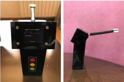
The device designed for bite force measurement was made of a sensor for receiving the bite force, a liquid crystal display (LCD) for immediate display of the results, and a system for quick calibration of the device in office. FSR-402 sensor (Interlink Electronics; USA) was selected due to their availability in the market and the range of required force. The sensor was suitable in size for placement in the mouth, sterilizable for reuse, and contained biocompatible material. It was also capable of measuring large bite force range up to 90 kg with high repeatability. Table 1 shows the characteristics of the applied sensor and Figure 1 displays the force-resistance curve.
According to previous reports, the bite force would possibly reach 90 kg, which was beyond the manufacturer’s recommended range for FSR
sensor and would result in nonlinear behavior in resistance variation. Thus, the sensor needed to be calibrated before each use through methods such as lookup table or embedded calibration relationships by using a processor for converting the resistance to force.
In addition, the circuits proposed for establishing the sensor needed to be investigated so that actuating the sensor in a range higher than its usual range would not damage the sensor. Resistance variations of the sensor were measured in initial experiments and the results are shown in Figure 2. According to the manufacturer’s proposed circuit,
the actuation resistance was approximately set to 250 ohms. Low startup resistances were used in this circuit to yield proper variations of the output voltage within the variation range of input force, so that the measurement would be done at high accuracy. (Figure 3)
To provide a secure current range for the sensor operation, the sensor was replaced and the resistance was actuated through changing the structure of the circuits proposed by the manufacturer. The values measured by the sensor were instantly displayed on the 2-inch color LCD (Figure 4).
A platform was also required to be designed so that Table 1: The characteristics of the applied sensor
Parameter Value
Force sensitivity range <100 g to >10 kg, depending on mechanics
Pressure sensitivity range <0.1 kg/cm2 to >10 kg/cm2, depending on mechanics Part-to-part repeatability ±15% to ±25% of established nominal resistance a Single part repeatability ±2% to ±5% of established nominal resistance a
Cutoff frequency 500 Hz
Device rise time 1-2 msec
Resolution 0.5% full scale
Current consumption FSR-400: 0.2 mA, FSR-402: 1.3 mA
Power draw FSR-400: 0.66 mw, FSR-402: 4.3 mW
Lifetime >10 million actuations
Package size FSR-400: 7.5 mm × 38.1 mm, 0.30 mm thickness FSR-402: 18.3 mm × 54.1 mm, 0.46 mm thickness
it could embed the force measurement sensor. The accurate 3D printer used for making the sheath, not only met the tolerances required for the dimensional optimality, but also could stand higher forces. In order to apply the initial force, distribute it on the sensitive surface of the sensor, and increase the sensor stability, Neodymium magnets were used to connect both sides of the sensor sheath to the surface of sensor; then, the force was applied to both sides of the sensor.
For better distribution of force and creating a proper effective contact area, a thin stereolithographic apparatus (SLA) polymer layer was inserted between the magnets and FSR sensor. Polymer layers were necessary for transmitting the force with respect to the sensor structure and the manufacturer suggested instruction. O-ring sealing
was used to prevent fluids penetration into the sensor and to allow sensor sterilization. Figure 5 illustrates the general scheme of the sensor sheath and cross section of the sheath.
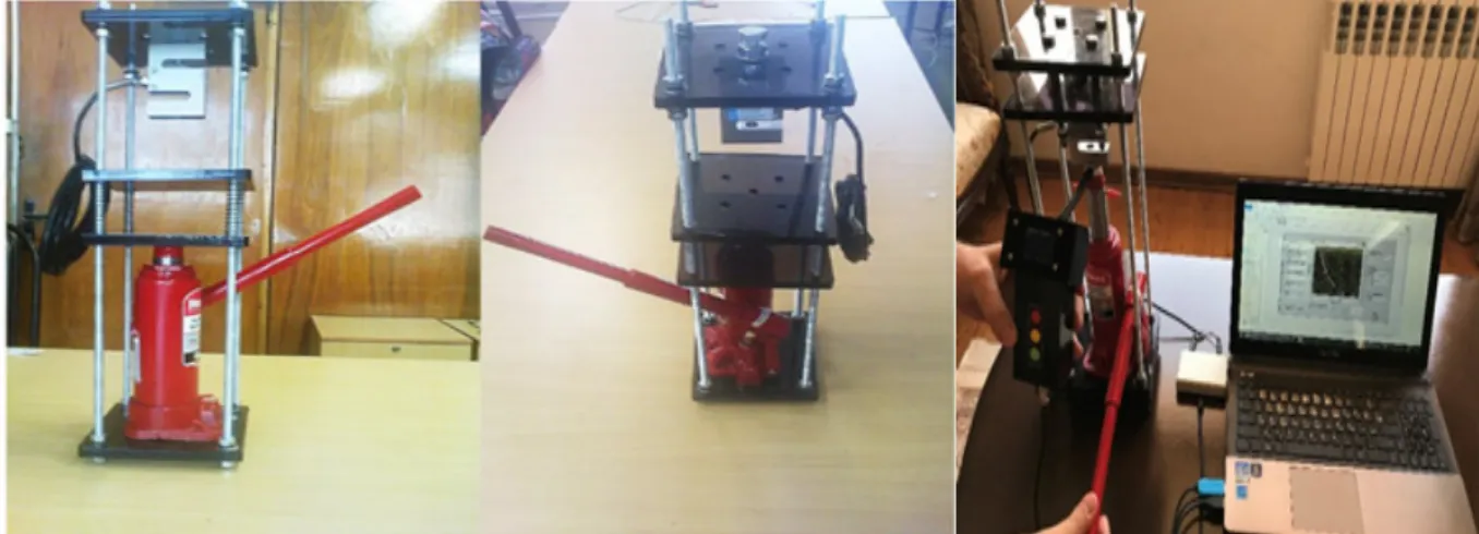
In order to calibrate the sensor, a manual calibration system was connected to a PC and the force required to apply pressure onto the sensor was created by using actuation jack. Having pumped the oil in the oil jack and displacing the moving heads of the device, the load cell measured the force applied to the sensor by the jack and transferred it to the computer calibration program through the computer interface circuit.
The force values of force measurement, which were transmitted to the computer through the sensor data logger, were used as the inputs of curve fitting program. Figure 6 shows the voltage
Figure 2: Resistance variations vs. force applied to the sensor
variations of the input versus the applied force and fitting parameters of the mathematical model. The calibrator used in this study was built based on the range of applied forces (Figure 6). In order to reduce the costs, the manual oil jack that actuated the moving heads of the device was used to apply force to the sensor. The design of the sensor allowed simultaneous receiving and recording of the input force and the data from the logger (Figure 7). By using the input data and computer software and according to the calibration-fitting program, calibration factors were calculated and transferred to the logger. Accordingly, the logger measured the force applied to the sensor, which was transmitted to the computer for calibration. A user interface program was designed for calibration to calculate the calibration factors automatically upon receiving the measured data from the data logger and calibrator. The measured data were then transmitted to the data logger of the sensor upon verification of the user. Consequently, this would update the calibration factors of the internal microprocessor.
According to the calibration data obtained from the calibration device, the associated force was calculated. In order to confirm the validity and reliability of the device, a digital dynamometer and a load cell (3-500 kg) were used to apply force on the sensor in nine values from 110 to 800 N twice. Finally, the ideal force, mean measured force, absolute error, and error percentage were determined.
Figure 4: bite force measuring device
Figure 5: (a) General scheme, (b) schematic of the sensor sheath’s cross section, (c) sensor diameter
)a(
)b(
Results
Table 2 demonstrates the bite force intensity. Accordingly, the mean relative error within the 11-80-kg range was about 2%. The lowest error percentage was 0.46% at 52-kg load and the highest was 3.97% at 28-kg load. The error percentage was 2.51% in the lowest range (11 kg) and 2.65% in the highest range (80 kg). Figure 8 shows the relation between the applied load and percentage error. Accordingly, the error percentage in different ranges did not follow a particular trend. Figure 9 demonstrates the relation between the measured load and the applied load; the line slope is approximately 1.
Discussion
This study presented the construction of a novel bite force-measuring device. The experiment approved the potential of the mentioned device for bite force measurement. The paramount superiority of this device is its low price, which makes it quite cost-effective. The device can be simply calibrated with a user-friendly appliance in the office; which facilitates the calibration process and help saving times and cost. Another advantage is the LCD that shows the results of measurement immediately. It can also measure the forces up to 90 kg with high precision. Moreover, the sensor size is suitable for placement in mouth and it can be sterilized.
General model Coeff. “a” Coeff. “b” Goodness of fit:
SSE: Goodness of fit:R-square:
f(x) = a*exp(b/x) 0.005064 1.71e+04 0.1456 0.9908
Figure 6: nonlinear variations of the applied voltage vs. force and table of mathematical model agreement with experimental data
Figure 8: Measurement error
Figure 9: Measured load versus the applied load
Table 2: Ideal force versus errors
Ideal force Mean of measured force Absolute error Error percentage
11 11.27 0.27 2.51
20 20.67 0.67 3.35
28 26.89 1.11 3.97
40 40.7 0.7 1.75
52 52.24 0.24 0.46
60 60.76 0.76 1.26
68 67.19 0.81 1.20
73 71.89 1.11 1.52
JBiomech. 2016;49:2877-2881.
2. Van Der Bilt A, Tekamp A, Van Der Glas H, et al. Bite force and electromyograpy during maximum unilateral and bilateral clenching. EurJOral Sci. 2008;116:217-222.
3. Yen CI, Mao SH, Chen CH, et al. The correlation between surface electromyography and bite force of mastication muscles in Asian young adults. Ann Plast Surg. 2015;74:168-172.
4. Cerna M, Ferreira R, Zaror C, et al. Validity and reliability of the T-Scan® III for measuring force under laboratory conditions. J Oral Rehab. 2015;42:544-551.
5. Owais AI, Shaweesh M, Abu Alhaija ES. Maximum occlusal bite force for children in different dentition stages.EurJOrthod. 2013;35:427-433.
6. Sun KT, Chen SC, Li YF, et al. Bite-force difference among obese adolescents in central Taiwan. J Formos Med Assoc. 2016;115:404-410.
7. Calderon PS, Kogawa EM, Lauris JR, et al. The influence of gender and bruxism on the human maximum bite force. J Appl Oral Sci. 2006;14:448-453.
8. Fernandes CP, Glantz PO, Svensson SA, et al. A novel sensor for bite force determinations. Dent Mater. 2003;19:118-126.
9. Harada K, Watanabe M, Ohkura K, et al. Measure of bite force and occlusal contact area before and after bilateral sagittal split ramus osteotomy of the mandible using a new pressure-sensitive device: a preliminary report. J Oral MaxillofacSurg. 2000;58:370-373. 10. Ueki K, Marukawa K, Shimada M, et al.
Changes in occlusal force after mandibular ramus osteotomy with and without Le Fort I osteotomy. Int JOral MaxillofacSurg. 2007;36:301-304.
11. Castelo PM, Gavião MB, Pereira LJ, et al. Masticatory muscle thickness, bite force, and occlusal contacts in young children with unilateral posterior crossbite. Eur J Orthod. 2007;29:149-156.
12. Koc D, Dogan A, Bek B. Bite force and influential factors on bite force measurements: a literature review.Eur J Dent. 2010;4:223-Although T-Scan III is among the most common and
well-known systems for bite force measurement, is not valid enough for measuring absolute values of occlusal force. The bite force applied on this system depends on the patient’s position and the location of the occlusal contacts. Therefore, it may record different values each time and show misleading bite force values [26]. T-Scan III is not reliable for measuring relative force [27], and is costly when full arch analysis is not required [16]. Furthermore, T-Scan III needs a USB wire to connect to the PC for setting up system [28]. Whereas, our device is wireless and does not need a PC during measurement, since the clinician can observe the bite force value on the LCD of the device.
The Dental Prescale System (Fuji Film; Tokyo, Japan) consists of a horseshoe-shaped pressure sensitive sheet (50H, R type) and a computerized scanning system (FPD705) [29]. Unlike the device presented in this study, Dental Prescale System is a costly system and does not provide information instantly. This novel measuring bite force device can measure absolute bite force with 2% error. Yet, further studies are suggested to reduce the error percentage and decrease the sensor sheath size.
Conclusions
With respect to the ease of calibration, cost-effectiveness, and accuracy of measurement, the proposed device is considered a user-friendly appliance, which can be simply used, in routine practice.
Acknowledgments
The authors thank the vice-chancellery for research and technology of Shiraz University of Medical Sciences, for supporting the research (Grant#13632). This paper is extracted from a thesis by Dr. Ali Peyravi.
Conflict of Interest: None declared.
References
1. Umesh S, Padma S, Asokan S, et al. Fiber Bragg grating based bite force measurement.
232.
13. Shinogaya T, Bakke M, Thomsen CE, et al. Bite force and occlusal load in healthy young subjects--a methodological study. Eur JProsthodontRestor Dent. 2000;8:11-15. 14. Rane V, Hamde S, Agrawal A. Development of
computerized masticatory force measurement system. J Med Eng Technol. 2017;41:65-71. 15. Testa M, Di Marco A, Pertusio R, et al. A
validation study of a new instrument for low cost bite force measurement. J Electromyog Kinesiology. 2016;30:243-248.
16. Fastier-Wooller J, Phan HP, Dinh T, et al. Novel low-cost sensor for human bite force measurement. Sensors. 2016;16:1244.
17. Kerstein RB. Articulating paper mark misconceptions and computerized occlusal analysis technology. DentImplantolUpdate. 2008;19:41-46.
18. Baltrusaityte A, Surna A, Pileicikiene G, et al. The relationship between unilateral mandibular angle fracture and temporomandibular joint function.Stomatologija. 2014;16:87-93.
19. Liu CW, Chang YM, ShenYF, et al. Using the T-scan III system to analyze occlusal function in mandibular reconstruction patients: A pilot study. Biomed J. 2015;38:52-57.
20. Lila-KrasniqiZD, Shala KS, Pustina-Krasniqi T, et al. Differences between centric relation and maximum intercuspation as possible cause for development of temporomandibulardisorder analyzed with T-scan III. Eur JDent. 2015;9:573.
21. Kogawa E, Calderon P, Lauris J, et al. Evaluation of maximal bite force in temporomandibular disorders patients.J Oral
Rehab. 2006;33:559-565.
22. Waltimo A, Könönen M. A novel bite force recorder and maximal isometric bite force values for healthy young adults. EurJournal Oral Sci. 1993;101:171-175.
23. Tekscan Force Sensors for Design. (accessed on 10 March 2016) Available at: [ https://www. tekscan.com/sites/default/files/FLX-Force-Sensors-For-Design.pdf].
24. Diaz Lantada A, Gonzalez Bris C, Lafont Morgado P, et al. Novel system for bite-force sensing and monitoring based on magnetic near field communication. Sensors. 2012;12:11544-11558.
25. Bousdras VA, Cunningham JL, Ferguson-Pell M, et al. A novel approach to bite force measurements in a porcine model in vivo.Int JOral Maxillofac Surg. 2006;35:663-667. 26. Lee SM, Lee JW. Computerized occlusal
analysis: correlation with occlusal indexes to assess the outcome of orthodontic treatment or the severity of malocculusion. Korean J Orthod. 2016;46:27-35.
27. Cerna M, Ferreira R, Zaror C, et al. In vitro evaluation of T-Scan® III through study of the sensels.CRANIO®. 2015;33:300-306.
28. Kerstein RB. History of the T-Scan system development from 1984 to the present day. Handbook of Research on Computerized Occlusal Analysis Technology Applications in Dental Medicine 2015; 1-35.
29. Kwon HK, Yoo JH, Kwon YS, et al.Comparison of bite force with dental prescale and unilateral bite force recorder in healthy subjects.J Korean AcadProsthodont. 2006;44:103-111.