Proceedings of the
Eighth International Workshop on
Graph Transformation and Visual Modeling Techniques
(GT-VMT 2009)
Ten virtues of structured graphs
Roberto Bruni and Alberto Lluch Lafuente
20 pages
Guest Editors: Artur Boronat, Reiko Heckel
Managing Editors: Tiziana Margaria, Julia Padberg, Gabriele Taentzer
Ten virtues of structured graphs
Roberto Bruni1and Alberto Lluch Lafuente1
1[email protected] 2[email protected] Dipartimento di Informatica, Universit`a di Pisa
Abstract: This paper extends the invited talk by the first author about the virtues of structured graphs. The motivation behind the talk and this paper relies on our experience on the development of ADR, a formal approach for the design of style-conformant, reconfigurable software systems. ADR is based on hierarchical graphs with interfaces and it has been conceived in the attempt of reconciling software ar-chitectures and process calculi by means of graphical methods. We have tried to write anADR agnosticpaper where we raise some drawbacks of flat, unstructured graphs for the design and analysis of software systems and we argue that hierarchi-cal, structured graphs can alleviate such drawbacks.
Keywords:Hierarchical graphs, Graph Grammars, Visual Languages
If you can find something everyone agrees on, it’s wrong— M. Udall
1
Introduction
Graph-based notations, techniques and tools play a fundamental role in the analysis of complex systems: on the one hand they rely on a solid mathematical basis, on the other hand they make it possible to render the formal analysis in visual notation best accessible for non graph theorists, like business analysts.
However, the complexity of modern software systems like those emerging in global comput-ing and in service oriented architectures is such that the “representation distance” w.r.t. ordinary graph transformation methodologies has grown larger and larger and poses serious problems in terms of issues such as, e.g., scalability, open endedness, dynamicity and distribution. Fur-thermore, the same kind of complication hampers indiscriminately all phases involved in the modeling process (specification, design, validation and verification).
We aim to show that one good way to tackle complexity and to enhance efficient formal rea-soning is to superimpose some structure on complex graphs, a general consideration that finds application in several different contexts where graphical notations are widely adopted and stan-dardized (e.g., Unified Modelling Language, Petri nets, BPEL and other workflow models, ref-erence modeling languages, process calculi encodings). In other words, we propose to consider structured graphs instead of flat graphs.
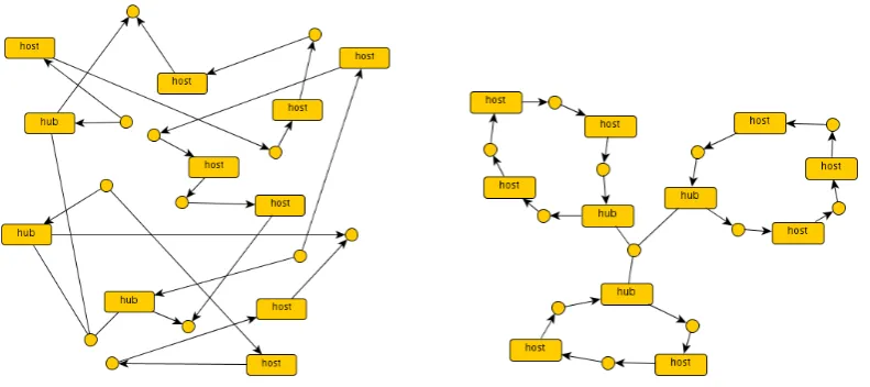
Figure 1: Two different drawings of the same network
graphs [DHP02,DHJ+08], shaped graphs [HM04] and designs [BLMT08] (our own contribution to this field).
We will discuss the benefits of using structured, hierarchical graphs over unstructured, flat graphs in the context of ten key aspects that arise in the graph-based engineering of software systems. More precisely, we shall consider design issues such as understandability (Section2), abstraction (Section3.2), composition (Section3.3) and requirements specification (Section3.1), dynamic aspects like behaviour (Section5.1) and reconfiguration (Section5.2), and analysis ac-tivities such as model finding (Section 4.1), conformance (Section 4.2) and verification (Sec-tion6). Last, we survey a particular application of graphs: the visual encoding of process calculi (Section7). Final remarks are in Section8.
2
Understanding graphs: Parsing and Browsing
Graphs find important applications as a convenient visual formalism in many different fields, ranging from software engineering, database and web design to networking, systems biology, global and grid computing, to cite a few.
Through visual interfaces, graphs give the possibility to grasp at one glance the connection between the represented entities (think e.g. of entity-relationship diagrams, UML class diagrams, folder trees in virtual desktops).
diame-ters and node distance to visualise different kinds of semantic information.
In the case of large monolithic graphs, visual notation begins to suffer from the same limita-tions as the textual notation, because it can be problematic for the user to parse, find and browse the portion of the graph more relevant to her/him. In this sense, automatic drawing techniques are also important for visual rendering.
A first virtue of structured graphs is overcoming several limitations related to the textual and visual representation. To see this, let us consider the representation of networks that connect different kinds of nodes including hosts and hubs. This kind of networks will be used as a running example over the paper.
Figure1shows two isomorphic flat graphs representing the same network, however it is ev-ident that the “logical” structure of the connection topology emerges better in the rightmost representation, which exposes the presence of three rings whose hubs are attached together to form what informally can be called a “star of rings”.
One can also note that a ring is just a line of hosts whose ends are connected to the same hub. This corresponds to fix a way to read the graph according to some sort of “blueprint” that explains how it is organised: at the topmost level there is the whole graph seen as a star of subgraphs, which in turn are all ring-shaped with a principal hub connected in line with a (possibly different) number of other components.
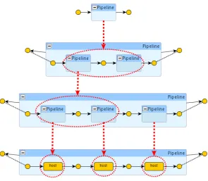
Recursively, one could think of a way to allow stars as components of rings, e.g. by introducing some adaptor components, like some special hubs. In this case, one would have to deal with even more complex networks, like the one in Figure 2, where the blueprint is made explicit: components are grouped by encircling them in a titled box (i.e. the type of the subnetwork) and titled boxes can be nested. For example, Figure 2 shows a network composed of three rings, where one of the rings contains a subnetwork with two rings. In this particular case, it is worth noting that the underlying flat graph would be ambiguous w.r.t. the proper structure of the network, as a different parsing could place the two leftmost rings as nested within the central one, and the two rightmost rings at the top layer.
Our point is that having some sort of “blueprint” of the graph would help to predicate over relevant subgraphs. For example, exposing the structure of the network can e.g. help in organis-ing software updates or load balancorganis-ing policies and also to carry inductive proofs of properties. It also allows for posing the attention to and navigate through smaller coherent portions of the graph. Finally, it will be argued later that the hierarchy structure makes it possible to define textual notation that is machine-readable and human-readable at the same time.
3
Designing Graphs
3.1 Requirements and Specification
Graph-based approaches to software engineering (e.g. [BP05,BH04]) often reduce the speci-fication of static (i.e. topological, structural) requirements to the characterisation of a set of graphs (those that fulfil the requirements) and requirement conformance to set membership. In our scenario, for instance, a requirement can be thatnetworks must be ring-shapedwhich must be modelled by characterising in some way the set of ring-shaped graphs.
Figure 2: A structured network with some explicit blueprint
(a) (b) (c)
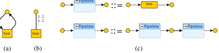
Figure 3: A type graph (a), an entity/relation diagram (b) and graph grammar production (c).
least sufficiently large (such asall ring-shaped graphs with at most n hosts) to make an enumera-tive description cumbersome when not unfeasible. A variety of mechanisms have been developed and are used to finitely describe sets of graphs in order to make, for instance, set membership decidable and, possibly, efficient. This issue will be discussed in more detail in Section4.2.
Type graphs have been traditionally used in graph transformation approaches [CMR+97] as a convenient way to label graph items with types and to constrain the way in which items can be interconnected. Type graphs have been used in various graph-based approaches to software engi-neering (e.g. [BBGM08,BHTV04]), but although they offer a simple and elegant mechanism for imposinglocalconstraints, their main limitation is the intrinsic difficulty to expressglobalones. To see this, considerline-shaped graphs. A type graph can express the fact that there is a particu-lar type of host which has two connections (tentacles) to a connection node (see Figure3(a)) but it is not possible to define a type graph that imposes requirements such asconnectivity(no host is disconnected) oraciclicity(hosts do not form rings). Intuitively, such properties areglobalin the sense that they regard the whole graph.
use of entity-relationship diagrams that introduce both a vocabulary of items (entities) and the way they can be related (relations). A difference with type graphs that makes such diagrams a bit more flexible is the possibility to impose cardinality constraints. We can, for instance, impose an entity of typehost to be connected to at least one and at most two connection nodes and, vice versa, we can impose each connection node to be related to at least one and at most two hosts of type host (see Figure 3(b)). However, this is still not sufficient to characterise line-shaped networks: there are infinitely many collections of hosts that satisfy the former cardinality constraint while not being line-shaped.
To tackle such limitations of UML specifications, complementary mechanisms have been de-veloped, such as the Object Constraint Language (OCL). The main idea is to impose further logic-based constraints over admissible graphs. Such mechanisms are not new in the research area of graphs. Indeed, Courcelle has thoroughly studied logics for graphs and their expressive-ness. One of the examples in his works is the well-known fact that graph reachability (required to characterise connectivity) cannot be expressed in first-order logic: second-order logic is needed. Courcelle has developed theMonadic Second-Order ogic for graphs(MSO) and has studied its expressiveness in comparison tograph grammars[Cou97].
Graph grammars [CMR+97,EHK+97] are another fundamental approach to characterise graph sets by providing a grammar that inductively generates all the graphs of the set. A promi-nent example are Hyperedge Replacement Grammars [Hab92] that can be considered as the equivalent of traditional context-free grammars. In the context of software architectures, for instance, this approach was first proposed in [M´et98] and subsequently followed by various au-thors [HM04,BLMT08]. Graph grammars do also have some limitations. For instance, it is well-known that a context-free graph grammar cannot characterise the set of all regular grids [Hab92]. The mentioned approaches can be considered as complementary and can be used together to express complex system requirements. The most evident example is UML technology. Another analogy in this regard can be done withMembership Equational Logic[Mes98] andtype systems for programming languageswhere a generative mechanism (e.g. the signature, the syntax) char-acterise themaintypes (i.e. sets of elements) and deduction mechanism based on inference rules are used to characterise more refined subtypes.
Which is the most convenient mechanism to deal withstructuredgraphs? In [BBG+08] it is argued that logic-based definitions are more suitable when the system under study is in a primi-tive state where the actual requirements (and hence the structure) are not well-understood and are refined again and again (which mainly amounts to adding, removing or modifying predicates). Instead, when the requirements become mature and the structure of the graphs becomes clear, then inductive definitions seem better suited.
Inductive mechanisms such as graph grammars (that also includes type graphs) provide unique advantages. Consider the example of line-shaped graphs. An inductive definition simply says that a line-shaped graph is a host with two ports or the concatenation of two line-shaped graphs (see Figure 3(c)) and the derivation tree explains the structure of the graph (how it has been generated).
(a) (b)
(c)
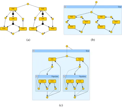
Figure 4: A flat, explicitly structured graph (a), a flat, implicitly structured graph (b) a hierarchi-cally structured graph (c).
X is a set of nodes,a,b,yandzare nodes,Rabbreviates the existence of an edge between two nodes. Predicates b) an c) can be formalized in a similar way.
While the MSO formulae are essentially (rather unstructured) logical sentences, the inductive definition is in some sense astructureddefinition, amenable to inductive reasoning and enjoying nicecompositionalfeatures as we shall discuss in Section3.3as well as having further virtues that we shall continue highlighting in the rest of the paper.
3.2 Abstraction and refinement
complex system at different levels of granularity, abstracting away subsystems whose details are not relevant at that point. When needed,refinement can reveal the internals of an abstract com-ponent. Another advantage of the use of abstraction and refinement arises in presence of open systems, where some parts of the system are not specified. In sum, abstraction is a fundamental aspect that enablesscalability,understandability, andmodularity.
Unfortunately, flat graphs are not a completely satisfactory model to deal with abstraction layers. Layers in flat graphs are typically modelled using a tree-like structure. A prominent approach that follows this spirit are Milner’s bigraphs [JM03] where the locality structure and the (unstructured) communication topology are represented by two overlapping graphs: a tree for locality, called theplace graph, and an arbitrary graph for communication, called the link graph. Still superimposing some structure is different than explaining how such structure has been obtained, an option that is found in structured hierarchical graphs and has further benefits.
As a simple example that regards our running scenario, consider a network formed by a star of rings, where a ring is seen as a line closed in circle. Using flat graphs the logical grouping of the hosts that form each line, for instance, must be encoded ad hoc (e.g. using the tree structure denoted with the edges of typesubin Figure4(a)) to avoid confusion. The resulting structure becomes complex, hard to understand and to manipulate.
An inductive definition of graphs (as explained in Section 3.1) by means, e.g. of context-free graph grammars [Hab92], can mitigate the problem. The best analogy one can offer is the functional reading of a grammar, where syntactical categories are seen astypes. So, implicitly, a graph produced by a graph grammar has a parsing and a type and so do its (proper) subgraphs. The idea is then that such information can be recovered to understand or manipulate graphs in a layered way (see Figure4(b)).
Using hierarchical graphs (e.g. [DHP02, BLM09]) we can combine the benefits of tree-like structuring of layers with the inductive definition of graphs. In a way, the layering is encoded within the graphs by the use of hierarchical edges, i.e. edges that contain graphs (Figure4(c)). For this purpose, the notion of interface becomes crucial as it represents the relation between an abstract component (hierarchical edge) and its internal details (graph). We will see this in Section4.1.
3.3 Composition
We have seen in Section3.2that structured graphs enable modularity and top-down development by refinement. We will see here that they facilitate bottom-up development by composition, as well.
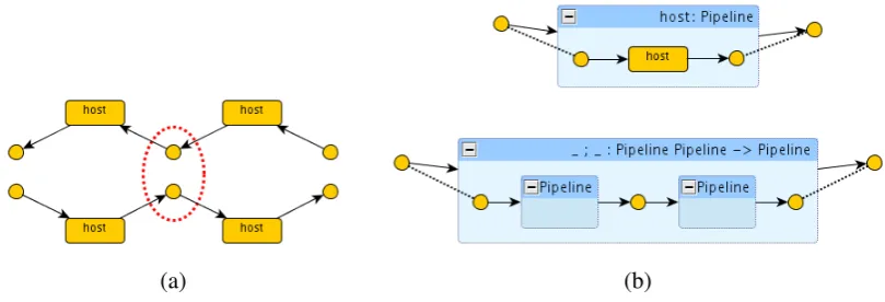
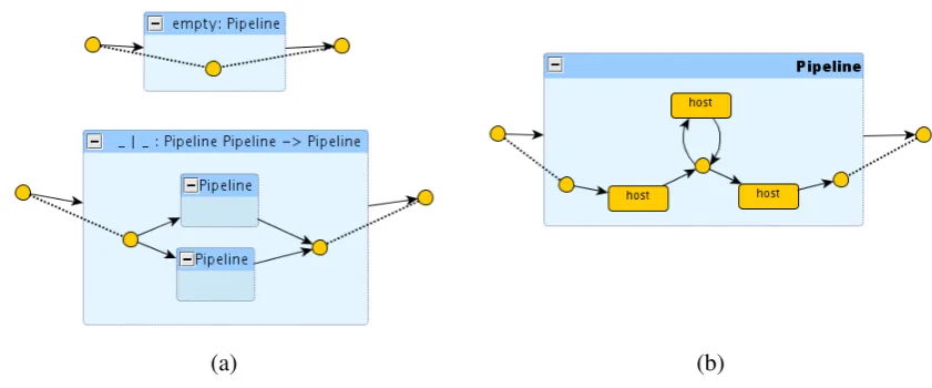
Arbitrary compositions can result in ill-shaped systems. For example, Figure 5(a) shows a broken pipeline obtained as the union of two pipelines and an incorrect attempt to repair it by fusing two nodes. This is the main disadvantage of flat graphs, i.e. they do not have an explicit mechanism to define the legal operations that can be used for composing larger graphs.
(a) (b)
Figure 5: A free composition (a) and a functional production (b).
A graph interface is usually formed by askin(the external aspect of the graph) and a relation between the skin and the graph itself (usually called thebodygraph). A typical mechanism (used e.g. in [DHJ+08,BLMT08]) is to use a hyperedge as the skin and to define a relation between the surrounding nodes the edge is attached to and some nodes of the body graph. Other mecha-nism have been proposed and are used for instance in ranked graphs [Gad03], bigraphs [JM03], syntactic grap judgments [FHL+06] and borrowed contexts [EK06].
The notion of graph interface facilitates the development of composition mechanisms. Var-ious such notions can be found in the literature. For instance, compositions for graphs with name interfaces [Gad03] operate by disjointly unifying graphs and merging their common nodes (those declared in the interfaces). Other, more complex compositions can also be found for bigraphs [JM03].
In all such cases, a disciplined, structured way of composing graphs is given by means of some graph algebra. Context-free graph grammar approaches to requirements such as those mentioned in Section3.1provide a unique advantage in this sense: a functional reading of the grammar provides a set of well-formed compositions. For instance, Figure 5(b) depicts the functional reading of the productions in Figure3(c): the left-hand side of a production is now drawn as the enclosing box (interface), while the right-hand side is drawn as the enclosed graph. The first operation can be seen as a constant that returns a Pipeline formed by a single host, the second operation takes two arguments of type Pipeline, concatenates them and returns the resulting Pipeline (the order of the arguments is usually implicit in the graphical drawing, along occidental reading convention). Moreover, we can assign names to such operations, like those shown in the top-bars of the corresponding boxes and then have a correspondence between the term algebra over such operators and the flat/structured graphs that we can build. For example, the termhost;hostdenotes a pipeline with two hosts.
4
Analysing Graphs
Figure 6: Constructing a line using a grammar derivation.
accepted and that no erroneous model is allowed. In case some models are found that violate such assumptions, then the problem has to be reported as a feedback to possibly upgrade the specification of requirements. Thus, model construction and model conformance can play a prominent role during (and also after) the phase of requirements assessment.
4.1 Model construction
Once we have a first version of a system’s requirements we might want to study the set of systems that satisfy them, with the purpose of understanding better the requirements, finding inconsisten-cies with informal descriptions, or discovering missing specifications. This analysis activity has been coined by Daniel Jackson asmodel finding[Jac06].
Jackson’s approach is based on first-order logic and has been also applied to graph-based modelling [BBG+08]. The main idea is that Boolean variables and predicates are used to denote the presence or absence of graph items (edges, nodes, tentacles, possibly typed) and further predicates are used to characterise the requirements. Having fixed a bound on the admissible instances of each graph item, the set of all (bounded) graphs satisfying the requirements is given by all the possible ways of satisfying the Boolean predicate that results from combining the available items.
(a) (b)
Figure 7: Constructing a line using a grammar derivation.
graphs are thus not easily handled. This is mitigated in Alloy [Jac06] (the tool implementing Jackson’s approach) by introducing the predicates that represent the requirements (and thus the structure of graphs) which implicitly discard non-conformant instances. The efficiency of such mitigation is delegated to clever SAT solvers.
A similar situation arises when the structure of graphs is expressed inductively in terms of graph grammars. The unstructured case amounts to a grammar that can introduce any graph item in any possible way. Again the state space of graphs to be considered exploits combinatorially and hampers any reasonable analysis.
However, in presence of structured graphs the situation is different. For instance, consider a context-free grammar characterising pipeline-shaped graphs. The grammar does not only offer us simple way to construct all such graphs, but it also emulates a design-by-refinement construction on which we could also reason (see Section3.2). For instance, we can reason about the number of refinement decisions that an architect must take in order to achieve a certain network or how many different derivations are possible to achieve it.
As an example, suppose that in the initial requirement for our networks the production for an empty and parallel pipelines were also considered (see Figure7(a)). Then it would have been readily discovered that ill-shaped pipelines are possible, like the network in Figure7(b) that can be described by the termhost;(host|empty);host: the problem is due to the presence of the empty pipeline, whose misuse can introduce unexpected cycles since it introduces node fusions.
4.2 Model conformance
Useful analyses are concerned with checking whether a graph enjoys some characteristics like being well-typed, conformant to a certain architectural style or fulfilling some subtle require-ment. In all cases we refer to the problem of checking whether a graph is a model of some property asconformance.
(a) (b)
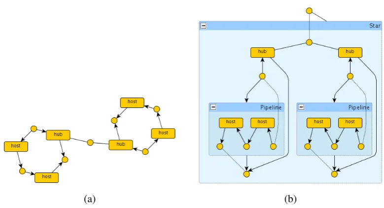
Figure 8: An unstructured (a) and a structured (b) graph to be analysed.
be characterised by means of some mechanism like graph grammars, various kind of diagrams and logical predicates. Checking conformance for an unstructured graph means then applying expensive algorithms to check if the graph can be derived from a graph grammar, satisfies the constraints of the diagrams or fulfils the logical predicate.
Structured graphs, instead, carry the “blueprint” as an immediate witness that the underlying graph is conformant to a certain architectural style or to certain constraints required by the origi-nal specification. A hierarchical, structured graph can carry even more information, because part of its blueprint might be present in the graph itself.
Suppose that we do not trust such blueprint and we want to check it for conformance. Consider the examples on Figure8depicting a flat graph (a) and a structured graph, both representing a star of rings.
Let us start with the unstructured graph. Checking conformance of a logical predicate poten-tially leads to consider each graph item (5 nodes and 6 edges) for each quantifier present in the predicate. Note that typical properties involve a non-trivial depth of quantifier nesting. A similar situation arises if we want to check conformance against a graph grammar, where (sub)graph isomorphism is a fundamental test which, again, might consider every graph item in the match.
(b)
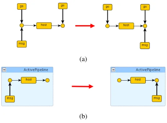
Figure 9: Behaviour rules for pipelines: conditional message passing using flat graphs (a) and hierarchical graphs (b).
5
Transforming Graphs
5.1 Behaviour
Graphs have a long tradition as a structure for representing static aspects such as data, topologies or architectures. Another example that we have seen in Section 3.1 is the use of graphs to represent the specification of static system requirements.
Graph are also used to represent dynamic system aspects such as the behaviour of a system. The main idea is that graphs are used to represent the state of a system and graph rewrites model the execution of the system. Various mechanisms for rewriting graphs have been pro-posed, ranging from the general-purpose graph transformation approaches by pushout construc-tion [CMR+97,EHK+97,EK06] or replacement [Hab92] to specific mechanism like those based on relative pushouts for bigraphs [JM03] or those based on multiple synchronisation for systems with mobility [FHL+06]. Overall, such models can account for complex graph manipulations by exploiting negative application conditions and sophisticated synchronisation mechanisms with the big advantage of their solid theories related to concurrency and distribution.
There are, however, some drawbacks in those cases in which flat, unstructured graphs are used. The first, obvious one regards the mechanism of rule matching. Basically, graph matching rules are based on subgraphs isomorphism, i.e. finding a part of the graph under consideration that matches the left-hand-side of a graph rewrite rule. The situation is similar to the one discussed in Section4.2: in absence of structure the matching algorithm must consider the whole graph, while structure in the graph limits the number of subgraphs to be considered.
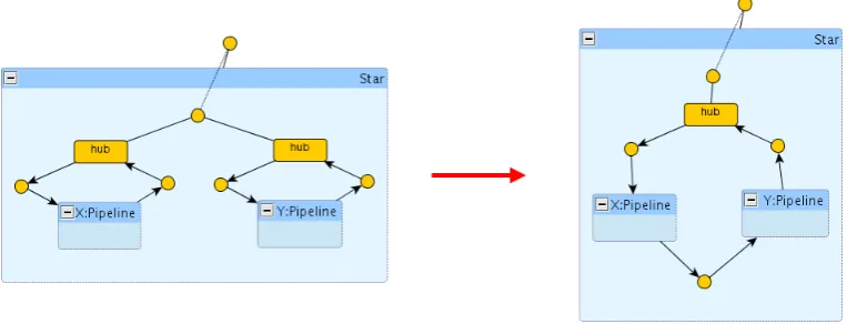
Figure 10: Reconfiguration rule to migrate hosts.
graph items that act as flags enabling or disabling the applicability of the rules (see [Gad03] for an example of graph-based pi-calculus semantics, where rewriting under prefixes is inhibited). Hierarchical graphs can be used as a more elegant and convenient graph version of the above mentioned term rewrite mechanisms.
Consider, for instance, that we want to model message passing in our running scenario, but we want to make it dependent on the status (active, non-active) of the network. Using flat graphs one can, e.g., decorate active hosts network points withgo-labelled edges. One rule for message passing would look like in Figure9 (a). One evident disadvantage is that our graphs will be full of active flags and that ad-hoc rules are needed to propagate the introduction or removal of those flags to enable or disable a part of the network. Using hierarchical graphs we could encode the network status information at the level of hierarchical frames, distinguishing between active and non-active pipelines. For instance, the rule in Figure9(b) conditions message passing for two hosts to be within an active frame.1 An additional disadvantage of using unstructured graphs is that the rules must be shown to be conformance-preserving, i.e. one must show that the rules cannot transform a valid graph into a graph that does not represent a valid system configuration. Structured graphs, instead, are a convenient ground to define structure-preserving graph transaformations. We will see an example in the next section.
5.2 Reconfiguration and Refactoring
We have seen in Section5.1that graph transformations can be used to model ordinary run-time behaviour. There are, of course, other interesting applications of graph rewrite systems like the computation of graph algorithms, model-driven refactoring or architectural reconfiguration.
In comparison to ordinary behaviour, the kind of transformations involved in the latter applica-tions might be very subtle and impose particular constraints. For instance, when reconfiguration
1 In concrete hierarchical graph transformation approaches the rule might need additional information that we
transformation rules.2 The main problem is that the containment of the ring might be formed by an arbitrary number of hosts or complex subnetworks. A complex program of rewrite rules is needed and several intermediate states must be considered, i.e. the transformation is not atomic. This is naturally accomplished by hierarchical graph transformation systems. Indeed, all we need is a rule like that informally depicted in Figure10which migrates a whole pipeline in one shot and guarantees that the resulting network is well-formed.
More subtle reconfigurations can take place, for instance involving a change in the interface of a system’s components or requiring synchronisation to agree on the common reaction to a certain failure. In all such cases the use of flat graphs imposes several challenges due to the need to directly manipulate individual graph items, to the eventual risk of having bad formed graphs as intermediate graphs during the reconfiguration and the need to show or verify that resulting graphs are well formed.
Hierarchical graphs can be helpful in those challenges since they allow to work on the struc-ture of graphs, to manipulate groups of items and to have a more disciplined control over the resulting interfaces and structure. In some cases (e.g. [BLMT08]) well formedness (e.g., style or metamodel conformance) must not even be proven: it can be guaranteed by construction.
6
Analysing Graph Transformations
We have already argued the convenience of structured graphs for the analysis of systems. In particular, we discussed the issue of checking whether a graph satisfies some static properties in Section4.2. This section, instead, regards the dynamic aspects of systems modelled via some kind of graph rewrite system.
Verification approaches for graph transformation systems mainly consist on some mechanism to specify properties and algorithms to check them. Various logics have been developed, for instance extending Courcelle’s Monadic Second Order logic (see [Cou97] and Section3.1) with temporal modalities [BCKL07]. An alternative approach is to use some kind of ad-hoc spatial logic, taking inspiration from Caires spatial logic for the pi-calculus [CC03]. An approach to structured graphs based, e.g. on disciplined ways ofcomposinggraphs can inspire the derived logical operators fordecomposinggraphs. This might result in ad-hoc efficient algorithms, but also in a property specification closer to visualisation and thus easier to use.
In any case, the model-checking problem can be very complex when not unfeasible due to the size of the state space and the expressiveness of the logics. Indeed, the presence of rules
(a) (b)
Figure 11: Two alternative encondings for pi-calculus process (νsecret) facebook(secret)
|facebook(message)|facebook(message).(internet(message)|mailbox(message)).
introducing new items and logical quantifiers nested with temporal modalities complicates the verification problem.
To mitigate such problems, standard verification techniques must be applied. Some approaches exist that apply abstract interpretation techniques for the verification of graph rewrite systems (see [BCK08] and the references therin) we argue that structured graphs can contribute further.
Indeed, as we have seen, structured graphs already offer a notable support for abstraction (c.f. Section3.2) and also for compositional issues (c.f. Section3.3). Consider for instance an approach based on context free graph grammars. Each syntactical category can be seen (in the functional reading) as a type. Such types can be used to define various abstractions. In our running scenario, for instance we might want to verify a particular network where we abstract away from all rings and we keep the full information of stars, only. Similarly, we can use the types to support a modular verification approach. Finally, we might show that some properties are inherent to rings or stars by structural induction.
7
Visual Encoding of Process Calculi
As exemplified by a vast literature, graphs offer a convenient ground for the specification and analysis of modern software systems with features such as distribution, concurrency and mobil-ity. In this section we shall discuss the convenience of structured graphs for a particular purpose: the visual encoding of process calculi.
commutativity of parallel composition graph isomorphism is not enough: a weaker graph equiv-alence notion is needed. Unfortunately, graph transformation approaches and tools are strongly based on graph isomorphism. Another drawback is that the graph requires additional annota-tions for identifying the root of the process (the program control), which nodes represent free or restricted names, and so on. Instead, the second encoding Figure11(b) is more convenient and elegant as it gets rid of the axioms for parallel composition by graph isomorphism, only. In addition, a suitable interface allows to see the whole graph as a process with well-identified root control and free names.
When the language is a process calculus, the encoding of a state is facilitated by the algebraic structure of states (i.e. processes are terms) and it is typically defined inductively on such struc-ture. However, the syntax of graph formalisms is often not provided with suitable features for names, name restrictions or hierarchical aspects. Typical solutions consist in developing an ad-hoc algebraic syntax, involving an implicit or explicit structuring of the graph formalism based, e.g., on set-theoretic definition of graphs with interfaces (e.g. [Gad03,GM08a]), enriched type systems (e.g. [BS06,GM08b]) or tree-based hierarchies (e.g. [JM03,GM08a]).
The less structured the underlying graphs are, the more cumbersome the encodings and their correctness proof become. A disciplined graph algebra provides in some sense a structured view of graphs and their legal compositions that facilitates the visual specification of processes and simplifies the proofs of correctness: the algebraic structure of both states and graphs enables proofs by structural induction and defines a bijection between processes and graphs.
One important advantage of graphical encodings is the intuitive visual modeling of complex systems, where the graph itself should offer an immediate characterisation of the represented system. This fact has been exploited with success, e.g., in the modeling of process calculi.
In the case of process calculi for modern systems like those around global computing and service oriented paradigms, there are some notions like sessions, transactions and nested com-pensations that require logical grouping of components or some notion of containment. For example, when a transaction is aborted it is important that all participants counteract. Again, when flat graphs are considered, some ad hoc encoding of containment is necessary.
8
Conclusion
We have discussed the advantages of structured graphs in up to ten different aspects of the graph-based engineering of software systems. Our arguments are mainly inspired by the various ap-proaches to structured (possibly hierarchical) graphs that can be found in the literature. It is out of the scope of this paper to overview all of them. Interested readers are referred to bi-graphs [JM03], hierarchical graph transformation [DHP02, DHJ+08], shaped graphs [HM04] and the references therein.
The main source of inspiration, however, is our own contribution to this field which is called Architectural Design Rewriting(ADR) [BLMT08]. ADR is a proposal for the design of com-plex software systems. The key features of ADR are: 1) hierarchical graphs with interfaces; 2) algebraic presentation; 3) inductively-defined reconfigurations.
Roughly, the underlying model consists of some kind of interfaced graphs whose inner items represent the architectural units and their interconnections and whose interface expresses the overall type and its connection capabilities. Architectures are designed inductively by a set of productions which enable: top-down refinement, like replacing an abstract component with a possibly partial realisation; bottom-up typing, like inferring the type of an actual architecture; well-formed composition, like composing some well-typed actual architectures together so to guarantee that the result is still well-typed. In the functional reading, the set of productions de-fines an algebra of terms, each providing a proof of style conformance. Hence, the interpretation of a proof term is the actual architecture.
The dynamics is then expressed by term rewrite rules acting over proof terms rather than over actual architectures. This has many advantages, like guaranteeing that all reconfigurations are style-preserving by construction.
The flexibility of ADR has been validated over heterogeneous models such as network topolo-gies, architectural styles and modelling languages. A prototypical implementation of ADR is also being developed using Maude [CDE+07], a high-performance tool implementing Rewriting Logic [MR07] and well suited for the approach as it offers native features such as conditional rewrite rules and built-in tools such as an LTL model checker. As an example, we have de-veloped a simple visualiser of algebraic specifications of hierarchical graphs. The web site of ADR (http://www.albertolluch.com/research/adr) makes both tools available and provides links to several additional resources.
There are still some open challenges in the field of graphs and graph transformation systems: mimicking standard and advanced term rewrite techniques such as structural operational seman-tics or symbolic semanseman-tics, representation of complex models from service oriented applications to biological systems, and so on. We expect that in all cases, the use of structured, hierarchical graphs will play a fundamental role.
Concurrency, Graphs and Models, Essays Dedicated to Ugo Montanari on the Oc-casion of His 65th Birthday. Lect. Notes in Comput. Sci. 5065, pp. 37–56. Springer Verlag, 2008.
[BBGM08] R. Bruni, A. Bucchiarone, S. Gnesi, H. Melgratti. Modelling Dynamic Software Architectures using Typed Graph Grammars. In Koenig et al. (eds.),Proceedings of GTVC’07. Elect. Notes in Th. Comput. Sci. 213.1, pp. 39–53. Elsevier Science, 2008.
[BCK08] P. Baldan, A. Corradini, B. K¨onig. Unfolding Graph Transformation Systems: The-ory and Applications to Verification. In Degano et al. (eds.),Concurrency, Graphs and Models, Essays Dedicated to Ugo Montanari on the Occasion of His 65th Birth-day. Lect. Notes in Comput. Sci. 5065, pp. 16–36. Springer Verlag, 2008.
[BCKL07] P. Baldan, A. Corradini, B. K¨onig, A. Lluch-Lafuente. A Temporal Graph Logic for the Verification of Graph Transformation Systems. InProceedings of WADT’06. Lect. Notes in Comput. Sci. 4409, pp. 1–20. Springer Verlag, 2007.
[BGL09] R. Bruni, F. Gadducci, A. Lluch-Lafuente. Graphical Representation of Process Calculi via an Algebra of Hierarchical Graphs. 2009. Manuscript available athttp: //www.albertolluch.com/papers/adr.algebra.pdf.
[BH04] L. Baresi, R. Heckel. Tutorial Introduction to Graph Transformation: A Software Engineering Perspective. In Ehrig et al. (eds.),Proceedings of ICGT’04. Lect. Notes in Comput. Sci. 3256, pp. 431–433. Springer Verlag, 2004.
[BHTV04] L. Baresi, R. Heckel, S. Th¨one, D. Varr´o. Style-Based Refinement of Dynamic Soft-ware Architectures. In Proceedings of WICSA’04. Pp. 155–166. IEEE Computer Society, 2004.
[BLM09] R. Bruni, A. Lluch-Lafuente, U. Montanari. Hierarchical Design Rewriting with Maude. In Rosu (ed.), Proceedings of WRLA’08. Elect. Notes in Th. Comput. Sci. 238.3, pp. 45–62. Elsevier Science, 2009.
[BLMT08] R. Bruni, A. Lluch-Lafuente, U. Montanari, E. Tuosto. Style-Based Architectural Reconfigurations.Bulletin of the EATCS94:161–180, 2008.
Ehrig, on the Occasion of His 60th Birthday. Lect. Notes in Comput. Sci. 3393, pp. 24–37. Springer Verlag, 2005.
[BS06] M. Bundgaard, V. Sassone. Typed polyadic pi-calculus in bigraphs. InProceedings of PPDP’06. Pp. 1–12. ACM, 2006.
[CC03] L. Caires, L. Cardelli. A spatial logic for concurrency (part I). Inf. Comput. 186(2):194–235, 2003.
[CDE+07] M. Clavel, F. Dur´an, S. Eker, P. Lincoln, N. Mart´ı-Oliet, J. Meseguer, C. Talcott. All About Maude - A High-Performance Logical Framework. LNCS 4350. Springer, 2007.
[CMR+97] A. Corradini, U. Montanari, F. Rossi, H. Ehrig, R. Heckel, M. L¨owe. Algebraic Approaches to Graph Transformation - Part I: Basic Concepts and Double Pushout Approach. InHandbook of Graph Grammars. Pp. 163–246. 1997.
[Cou97] B. Courcelle. The Expression of Graph Properties and Graph Transformations in Monadic Second-Order Logic. In Handbook of Graph Grammars and Computing by Graph Transformation. Pp. 313–400. World Scientific, 1997.
[DBL] DBLPVis Homepage.http://dblpvis.uni-trier.de/.
[DHJ+08] F. Drewes, B. Hoffmann, D. Janssens, M. Minas, N. Van Eetvelde. Shaped Generic Graph Transformation. In Proceedings of AGTIVE’07. Lect. Notes in Comput. Sci. 5088, pp. 201–216. Springer Verlag, 2008.
[DHP02] F. Drewes, B. Hoffmann, D. Plump. Hierarchical Graph Transformation.Journal on Computer and System Sciences64(2):249–283, 2002.
[dot] Graphviz Homepage.http://www.graphviz.org/.
[EHK+97] H. Ehrig, R. Heckel, M. Korff, M. L¨owe, L. Ribeiro, A. Wagner, A. Corradini. Algebraic Approaches to Graph Transformation - Part II: Single Pushout Approach and Comparison with Double Pushout Approach. InHandbook of Graph Grammars. Pp. 247–312. World Scientific, 1997.
[EK06] H. Ehrig, B. K¨onig. Deriving bisimulation congruences in the DPO approach to graph rewriting with borrowed contexts.Mathematical Structures in Computer Sci-ence16(6):1133–1163, 2006.
[FHL+06] G. L. Ferrari, D. Hirsch, I. Lanese, U. Montanari, E. Tuosto. Synchronised Hyper-edge Replacement as a Model for Service Oriented Computing. InProceedings of FMCO’05. Lect. Notes in Comput. Sci. 4111, pp. 22–43. Springer Verlag, 2006.
[Gra] GraphML Homepage.http://www.infosun.fim.uni-passau.de/Graphlet/GML/gml-tr. html.
[Hab92] A. Habel. Hyperedge Replacement: Grammars and Languages. Springer-Verlag New York, Inc., Secaucus, NJ, USA, 1992.
[HM04] D. Hirsch, U. Montanari. Shaped Hierarchical Architectural Design. InProceedings of GT-VMT’04. Elect. Notes in Th. Comput. Sci. 109, pp. 97–109. Elsevier Science, 2004.
[Jac06] D. Jackson.Software Abstractions: Logic, Language and Analysis. MIT Press, 2006.
[JM03] O. H. Jensen, R. Milner. Bigraphs and Mobile Processes. Technical report 570, Com-puter Laboratory, University of Cambridge, 2003.
[Mes98] J. Meseguer. Membership Algebra as a Logical Framework for Equational Specifi-cation. In Parisi-Presicce (ed.), Proceedings of WADT’97. Lect. Notes in Comput. Sci. 1376, pp. 18–61. Springer Verlag, 1998.
[M´et98] D. L. M´etayer. Describing Software Architecture Styles Using Graph Grammars. IEEE Trans. Software Eng.24(7):521–533, 1998.