Available online throug
ISSN 2229 – 5046
International Journal of Mathematical Archive- 8(1), Jan. – 2017 73
EFFECT OF HALL CURRENT ON MHD FLOW PAST A MOVING VERTICAL PLATE
WITH CONSTANT MASS DIFFUSION AND VARIABLE TEMPERATURE
U. S. RAJPUT
1, NEETU KANAUJIA*
21
Department of Mathematics and Astronomy, University of Lucknow, Lucknow – (U.P), India.
2
Department of Mathematics and Astronomy, University of Lucknow, Lucknow – (U.P), India.
(Received On: 17-12-16; Revised & Accepted On: 17-01-17)
ABSTRACT
I
n the present paper, effect of Hall current on MHD flow past a moving vertical plate with constant mass diffusion and variable temperature is studied. The fluid considered is an electrically conducting. The solution of the model is obtained by Laplace transform method. The effect of parameters is shown with the help of graphs. The velocity profile and Skin friction have been studied for different parameters. The effect of parameters are shown graphically and the value of the skin-friction for different parameters has been tabulated.
Key Words: MHD, Hall current, Skin friction, Heat and mass.
INTRODUCTION
The problems related to Hall current, heat transfer and mass diffusion are of great interest due to their applications in many processes. The effect of Hall current on MHD flows have been carried out by many authors due to its applications in the problems of MHD generators and Hall accelerators. Some related research works are mentioned here. Beg and Ghosh [1] investigated magneto hydrodynamic flow with oscillatory surface temperature. Mukherjee [6] investigated effect of radiation and porosity parameter on hydro magnetic flow due to exponentially stretching sheet in a porous media. Datta et al. [3] have studied oscillatory MHD flow over plate. Sato [9] analyzed the Hall effect on ionized gas between parallel plates. Yamanishi [10] has studied MHD flow between two parallel plates. Hall effect on MHD flow past an accelerated plate was investigated by Deka [4]. Chambre et al. [2] have studied the diffusion of chemically reactive species in a laminar boundary layer flow. Ibrahim et al. [5] have studied chemically reacting magneto hydrodynamic boundary layer flow over a moving plate with suction. Rajput and Kumar [8] have studied magneto hydrodynamic flow over exponentially accelerated plate. Earlier we [7] have studied MHD flow past an impulsively started vertical plate with variable temperature in the presence of Hall current. In this model, we are considering effect of Hall current on MHD flow past a moving vertical plate with constant mass diffusion and variable temperature.
MATHEMATICAL FORMULATION
The flow is unsteady and incompressible. The x axis is considered along the fluid motion. Magnetic field B0 of uniform
strength is taken perpendicular to x axis. Initially it has been considered that the fluid and the plate are at the same temperature (T∞). C∞ is the species concentration within the fluid. The plate starts accelerating after t = 0. The species concentration and temperature of the plate are raised to
w
C and Tw., respectively. The fluid model with usual
approximations is as under:
, ) ( ) 1 ( ) (
)
( 2
2 0 *
2 2
mw u m B C
C g T T g y
u t
u +
+ − − +
− + ∂ ∂ = ∂ ∂
∞ ∞
ρ
σ
β
β
υ
(1)
, ) ( ) 1
( 2
2 0 2
2
mu w m B
y w
t w
− +
− ∂ ∂ = ∂ ∂
ρ σ υ
(2)
, 2 2
y C D t C
∂ ∂ = ∂ ∂
(3)
Corresponding Author: Neetu kanaujia*
2. 2 2 y T C k t T P ∂ ∂ = ∂ ∂
ρ (4)
The following boundary conditions have been assumed:
(
)
.
y
as
T
,
,
0
,
0
0,
y
at
,
,
0
,
:
0
y,
of
values
the
all
for
,
,
,
0
,
0
:
0
2 0∞
→
→
→
→
→
=
−
+
=
=
=
=
>
=
=
=
=
≤
∞ ∞ ∞ ∞ ∞ ∞T
C
C
w
u
t
u
T
T
T
T
C
C
w
e
u
t
T
T
C
C
w
u
t
w w btυ
(5)Here u is the velocity of the fluid in x- direction, w - the velocity of the fluid in z- direction,
m
- Hall parameter, g –acceleration due to gravity,
β
- volumetric coefficient of thermal expansion,β
*- volumetric coefficient of concentration expansion, t- time,C
∞- the concentration in the fluid far away from the plate, C - species concentrationin the fluid ,
C
w- species concentration at the plate, D - mass diffusion,T
∞- the temperature of the fluid near theplate,
T
w - temperature of the plate, T - the temperature of the fluid , k - the thermal conductivity,υ
−
the kinematicviscosity,
ρ
- the fluid density,σ
- electrical conductivity,µ
- the magnetic permeability, and CP - specific heat atconstant pressure. Here
m
=
ω
eτ
e withω
e- cyclotron frequency of electrons andτ
e- electron collision time.To write the equations (1) - (4) in dimensionless from, we introduce the following non - dimensional quantities:
. ) ( ) ( , , ) ( , , ) ( , , , Pr , , , , 3 0 * 2 0 3 0 2 0 2 0 2 0 0 0 0 ∞ ∞ ∞ ∞ ∞ ∞ − − = − − = − = = − = = = = = = = = T T T T C C C C C u C C g Gm u b b u T T g Gr tu t u B M k C D Sc yu y u w w u u u w w w w P
θ
υ
β
υ
βυ
υ
ρ
υ
σ
µ
υ
υ
(6) Here the symbols used are:u
-dimensionless velocity,w
-dimensionless velocity,θ
-the dimensionless temperature,b
-dimensionless acceleration parameter C - the dimensionless concentration, Gr - thermal Grashof number, Gm - mass Grashof number,µ
- the coefficient of viscosity, Pr - the Prandtl number, Sc - the Schmidt number, M - the magnetic parameter.The dimensionless forms of Equations (1), (2), (3) and (4) are as follows
,
)
1
(
)
(
2 2 2m
w
m
u
M
C
Gm
Gr
y
u
t
u
+
+
−
+
+
∂
∂
=
∂
∂
θ
(7) , ) 1 ( ) ( 2 2 2 m u m w M y w t w + − − ∂ ∂ = ∂ ∂ (8) , 2 2 1 y C Sc t C ∂ ∂ = ∂ ∂ (9) . 2 2 Pr 1 y t ∂ ∂ = ∂∂θ θ (10)
The corresponding boundary conditions are:
© 2017, IJMA. All Rights Reserved 75 Dropping the bars and combining the Equations (7) and (8), we get
, ) 1 ( 1 2 2 2 q mi m M GmC Gr y q t q − + − + + ∂ ∂ = ∂ ∂
θ (12)
, 1 2 2 y C Sc t C ∂ ∂ = ∂ ∂ (13) . Pr 1 2 2 y t ∂ ∂ = ∂
∂θ θ
(14)
Here
q
=
u
+
iw,
with corresponding boundary conditions.
y
as
,
0
,
0
,
0
0,
y
at
,
1
,
,
0
,
,
:
0
y,
of
value
all
for
,
0
,
0
,
0
:
0
∞
→
→
→
→
=
=
=
=
=
>
=
=
=
≤
θ
θ
θ
C
q
C
t
w
e
q
t
C
q
t
bt (15)The solution obtained is as under:
2
0 2 13 1 13 14
1
1
{
(1 Pr
)}
(
)
{
(1 Pr)}
2
4
b t a b a y a y
q
e
A
y Gr A
at
a e
A
e
B
A
a
+ −=
+
+
− −
+
−
+
−
2 21 1 1
1 11 12
Pr 4 14
2
Pr 1 Pr 1 Pr
17
2
1 1 1
18 1
( (1 ))
2
1 Pr
Pr ( { 1 Pr } (2 Pr {1 [ ]})
2 2
1 1
Pr 1) Pr
1
[ 2 [ ] (1
2 2
at aSc aSc
a y Sc Sc Sc
y t
at a y
at a aSc
Sc y y
Sc Sc Sc
Gm e A e B e B
a
y
Gr y B at a e t y Erf
a t
e B
y
Sc y
Gm Erfc e B e
a t π π π − − + − + − + − − + − + − + − + − + + − + + + − − − + + + − − + −
− − + + + B19)]
(16) Pr 2 Pr 2 Pr Pr 4 2 2 − + = − π
θ e yt
t y Erf y t t y (17) . 2
= t y Sc Erfc C (18)
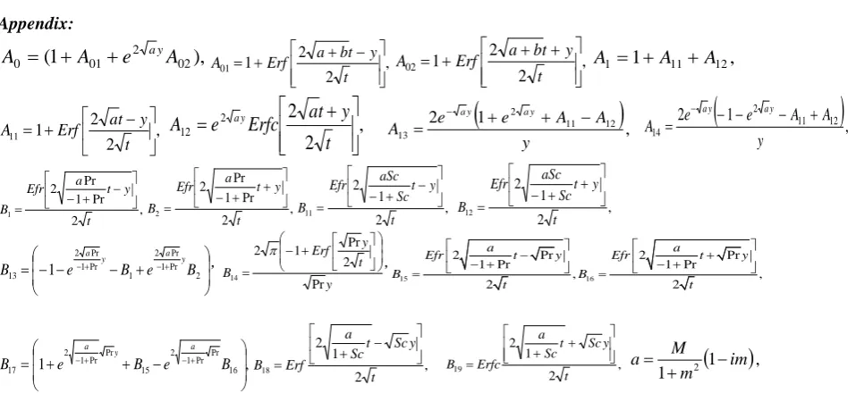
The expressions for the constants involved in the above equations are given in the appendix.
Skin friction
The dimensionless skin friction at the plate y = 0 is computed by
0 . x z y dq i
dy =
τ
τ
= +
Discussion and Results
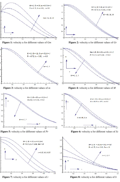
The numerical values of velocity and skin friction are computed for different parameters like Hall parameter (m), mass Grashof number (Gm), Schmidt number (Sc), time (t), thermal Grashof number (Gr), magnetic field parameter (M), Prandtl number (Pr), and (b) acceleration parameter. The values of the main parameters considered are:
m = 1, 5; Gm = 10, 20, 30; Sc = 2.01, 3, 4; t = 0.15, 0.2, 0.25; b = 1, 3, 5; Gr = 10, 20, 30; M = 1, 2, 5; Pr = 0.71, 7;
Figures 1, 2, 3, 7, and 8 show that primary velocity (u) increases when Gm, Gr, m, t and b are increased. Figures 4, 5,
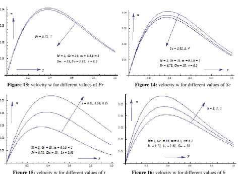
and 8 show that primary velocity (u) decreases when M, Pr, and Sc are increased. And figures 9, 10, 12, 15, and 16
show that the secondary velocity (w) increases when Gm, Gr, M, t and b are increased. Figures 11, 13 and 14 show that secondary velocity (w) decreases when m, Pr, and Sc are increased.
Skin friction is given in table 1. The value of
τ
x increases with the rise in Gm, Gr, m, and t. However, it decreases withM, b, Pr and Sc. Similar effects are observed with
τ
z when M, t Gm, Gr and b are increased thenτ
zincreases. Again,z
Figure 1: velocity u for different values of Gm Figure 2: velocity u for different values of Gr
Figure 3: velocity u for different values of m Figure 4: velocity u for different values of M
Figure 5: velocity u for different values of Pr Figure 6: velocity u for different values of Sc
© 2017, IJMA. All Rights Reserved 77
Figure 9: velocity w for different values of Gm Figure 10: velocity w for different values of Gr
Figure 11: velocity w for different values of m Figure 12: velocity w for different values of M
Figure 13: velocity w for different values of Pr Figure 14: velocity w for different values of Sc
Table – 1: For skin friction
M m Pr Sc Gm Gr b t
τ
xτ
z2 0.5 0.71 2.01 10 10 1 0.2 0.06781 0.25639
2 0.5 7.00 2.01 10 10 1 0.2 -0.10370 0.25212
2 0.5 0.71 3.00 10 10 1 0.2 -0.15335 0.24768 2 0.5 0.71 4.00 10 10 1 0.2 -0.30661 0.24228 2 0.5 0.71 2.01 20 10 1 0.2 2.06686 0.29742 2 0.5 0.71 2.01 30 10 1 0.2 4.06590 0.33846 2 0.5 0.71 2.01 10 20 1 0.2 0.42072 0.26216 2 0.5 0.71 2.01 10 30 1 0.2 0.77363 0.26790 2 0.5 0.71 2.01 10 10 3 0.2 -1.79420 0.32701 2 0.5 0.71 2.01 10 10 5 0.2 -4.82680 0.42573 2 0.5 0.71 2.01 10 10 1 .015 -0.33517 0.209744 2 0.5 0.71 2.01 10 10 1 0.25 0.39374 0.30292
1 0.5 0.71 2.01 10 50 1 0.2 0.33515 0.13467
5 0.5 0.71 2.01 10 10 1 0.2 -0.67460 0.55820 2 1 0.71 2.01 10 10 1 0.2 0.25966 0.33222 2 5 0.71 2.01 10 10 1 0.2 0.58427 0.13556
CONCLUSION
The conclusions of the investigation are as given:
• Primary velocity increases with the increase in Gr, Gm, b,m and t.
• Primary velocity decreases with M, Pr and Sc.
• Secondary velocity increases with the increase in Gr, Gm, M, b and t.
• Secondary velocity decreases with m, Pr and Sc.
•
τ
x increases with the rise in Gr, Gm, m, and t. •τ
xdecreases with α,M, b, Pr and Sc.•
τ
z increases with the rise in Gr, Gm, M, b and t.•
τ
zdecreases with m,Pr and Sc.Appendix:
),
1
(
01 2 020
A
e
A
A
=
+
+
ay ,2 2 1 01 + − + = t y t b a Erf A , 2 2 1 02 + + + = t y t b a Erf
A
A
1=
1
+
A
11+
A
12,
, 2 2 1 11 − + = t y t a Erf A
,
2
2
2 12
+
=
t
y
t
a
Erfc
e
A
ay 2(
1 11 12)
,2 13 y A A e e A y a y
a + + −
= − 2
(
1 11 12)
,2 14 y A A e e A y a y
a − − − +
= − , 2 Pr 1 Pr 2 1 t y t a Efr B − + − = , 2 Pr 1 Pr 2 2 t y t a Efr B + + − = , 2 1 2 11 t y t Sc aSc Efr B − + − = , 2 1 2 12 t y t Sc aSc Efr B + + − = + − − − = −+ −+ 2 Pr 1 Pr 2 1 Pr 1 Pr 2
13 1 e B e B
B y a y a , y t y Erf B Pr 2 Pr 1 2 14 + − = π , 15 16
2 Pr 2 Pr
1 Pr 1 Pr
, ,
2 2
a a
Efr t y Efr t y
B B t t − + − + − + = = , 1 16 Pr Pr 1 2 15 Pr Pr 1 2
17
− + +
= e −+ B e −+ B
B a y a , 2 1 2 18 t y Sc t Sc a Erf B − + = , 2 1 2 19 t y Sc t Sc a Erfc B + +
=
(
1),
1 m2 im M
a −
+ =
REFERENCES
1. Beg A. O. and Ghosh S. K., 2010, Analytical study of magneto hydro dynamic radiation-convection with surface temperature oscillation and secondary flow effects, International Journal of Applied Math & Mechanics, 6(6), pp. 1-22.
2. Chambre P. L. and Young J. D., 1958, On the Diffusion of a Chemically Reactive Species in a Laminar Boundary Layer Flow, Physics of Fluids, Vol. 1, pp. 48-54.
© 2017, IJMA. All Rights Reserved 79 4. Deka R.K., 2008. Hall effects on MHD flow past an accelerated plate, Theoret. Appl. Mech., Vol.35, No.4, pp.
333{346, Belgrade,
5. Ibrahim S. Y., and Makinde O. D., 2010, Chemically reacting MHD boundary layer flow of heat and mass transfer over a moving vertical plate with suction, Scientific Research and Essays, 5(19), pp. 2875-2882. 6. Mukherjee .B. and Prasad. N., 2014. Effect of radiation and porosity parameter on hydromagnetic flow due to
exponentially stretching sheet in a porous media, International Journal of Engineering, Science and Technology Vol. 6, No. 1pp. 58-70.
7. MHD flow past an impulsively started vertical plate with variable temperature in the presence of Hall current.
International Journal of Mathematical Archive-6(11), 2015, 120-127 ISSN 2229 – 5046
8. Rajput and Kumar, 2016, Unsteady MHD flow in porous media past over exponentially accelerated inclined plate with variable wall temperature and mass transfer along with Hall current. International Journal of Engineering, Science and Technology vol. 8, No. 2, 2016, pp. 1-10.
9. Sato H., 1961, The Hall effect in the viscous flow of ionized gas between parallel plates under transverse magnetic field, J. Phys. Soc. Jpn., 16, No. 7, 1427–1433.
10. Yamanishi T., 1962, Effect of Hall current on the steady hydromagnetic flow between two parallel a plates, in: Proc. 17th Annual Meeting, Phys. Soc. Japan, Vol. 5, Osaka, Japan, p. 29.
Source of support: Nil, Conflict of interest: None Declared.