Reference/Training
Manual
2005 20-20 GIZA 20-20 Technologies20-20 GIZA
Developed by: 20-20 GIZA Services
For Technical Support call: 800.638.6002 or 616.732.5517
Support hours: M - Th 8:00 AM - 7:00 PM Eastern Friday 9:00 AM - 5:00 PM Eastern
Customer Identification number: ________________ Check out our Web Site at www.2020office.com Email Address: [email protected]
Copyright 2005, 20-20 Technologies, Inc. Commercial Group
99 Monroe Avenue NW, Suite 400 Grand Rapids, MI USA 49503-2651
Tel 616 454.0000 Fax 616.454.4140
Printed in USA. Content subject to change without notice.
All rights reserved. No part of this publication may be reproduced, stored in a retrieval system, or transmitted, in any form or by any means, electronic, mechanical, photocopying, recording, or otherwise, without prior written permission from 20-20 Technologies.
Microsoft, Windows, Windows 98, Windows NT and Windows 2000 are registered trademarks of the Microsoft Corporation.
All other trademarks, service marks, products or services are trademarks or registered trademarks of their respective holders.
Contents
Contents i
GIZA Overview 1
GIZA Design Basic ...1
GIZA Design Enhanced ...1
GIZA Design Professional ...1
GIZA Specifier...2
Microsoft Windows 3 Features ...3
Desktop & Icons...4
Program Window Properties ...5
Start Button ...5
Data Storage & Windows Explorer...6
Working with Files and Folders ...6
GIZA Design 9 Introduction...9
Drawing Interface...10
Toolbar Overview ...10
Menus Overview – 2D CAD, Walls, Furniture placement...11
Draw Lines...13
Edit – Delete/Copy/Move...15
Fillet ...17
View Commands...18
Customizing the Toolbar...19
Draw Walls 21 Running Walls...22
Exercise...24
Saving the Drawing...25
Placing Interior Walls ...26
Exercise...27
Corner Editor...28
Modify Walls ...29
Placing Openings- Doors and Windows ...32
Moving Openings Using Slide ...33
Moving Openings Using 2-Point Slide ...33
Placing Openings at a Specific Distance ...34
Snap/Set Reference ...35
Exercise...35
Changing the Panel Reference ...51
Placing Worksurfaces...52
Placing Overhead Storage ...53
Placing Furniture at Specific Angles...55
Changing the Height of a Symbol ...56
Placing Pedestals...57
Placing Chairs ...57
Select Symbols Search Function – Exact Part Number...58
Select Symbols Search Function – Partial Part Numbers...59
Moving or Copying a Single Item...60
Moving Multiple Items ...60
Moving a Measured Distance...60
2 Point Move...61
Copying Multiple Items ...61
Mirror...62
Advanced Modification Tools...64
Specialized Symbol Placement ...66
Grids...66
Placing Symbols at a Specific Location ...68
Creating Typicals ...69
Placing Typicals...70
Placing Typicals on a Grid ...72
Tags...74
Selecting Items...75
Selection Sets ...76
Layers...78
Existing and New Furniture Using Pen Override...80
Masks ...83
Masks ...84
Using 3D in GIZA Graphics ...85
Render Options...86
Perspective Camera...90
Birds Eye View ...92
Bill of Materials (BOM)...93
Bill of Materials with Costs and Discounts...93
Export Bill of Materials to Excel Format...95
Printing...96
Vignette Plot ...98
Adding a Logo to a Drawing...99
Working With Templates...100
Selecting a Template ...103
Create new drawings without using a template...103
Apply a template to an existing drawing...103
Working with a Raster Background ...104
Working with AutoCAD Files ...105
Set Drawing Options ...107
GIZA Specifier 115 Introduction...115
Exporting a Bill of Materials from GIZA Graphics into Specifier...116
Saving a Project...117
Deleting Line Items...117
Adding Line Items...117
Selecting Options ...120
Changing Options...122
Resequence Line Item Numbers...124
Discounts...125
Line Item Discounts ...128
Additional Charges...128
Rename Labels...128
Project Totals ...130
Project Information ...131
Millennium Reports ...134
Preview Reports ...134
Print...134
Custom Reports...135
Export Reports ...139
Export to SIF Data for Order Entry...139
GIZA Automation 141 Introduction...141
Auto Hardware ...142
GIZA Frame Designer...143
Applying Frame Designs...147
Frame Designer Preferences...152
Advanced GIZA Design Topics 153 Introduction...153
Advanced Typical Placement...154
Make Symbol ...155
GIZA Specials...156
Adding Columns ...159
Check Drawing Integrity on Save ...162
Check Drawing Integrity of an Area ...162
Lightscape ...163
Inventory Management ...168
GIZA Publisher ...171
Advanced GIZA Specifier Topics 179 Introduction...179
Select Special ...180
User Library ...181
User Library Item Options ...183
Add to User Library ...184
Utilities...185
Advanced Option Features ...186
Option Sets...187
Appendix A 191 GIZA Graphics Toolbars...191
Installing Libraries to a Network Drive ...218
GIZA Overview
Welcome to the GIZA Design and Specification training course. This course is designed to fit the needs of space planners, sales people, facility managers, and designers. Through hands on training, you will develop furniture quotations, budget proposals, orders, and other documents used in the design, sales, specification, and management of systems furniture.
We will provide the detail assistance necessary for you to increase your production and give you a solid base for learning advanced features and techniques. We encourage you to ask questions. We have provided a well-trained staff available to answer your specific application questions. All students should have a basic familiarity with the concepts and practices of modern business office design and product knowledge.
GIZA Design Basic
GIZA Design Basic is the ideal tool for sales people. Some of the features include Icon Menus to aid product selection for particular product lines. The Panel Placer tool allows for accurate panel placement. Auto Hardware is included for some product lines that automatically place panel connectors. Panel Checker alerts you when overlapping panels occurs to aid you in determining proper panel placement. Frame Designer allows you to build frames up with skins when
available. Products brought into the drawing area are brought in on layers that allow for easy viewing and editing. You have the ability to place parts or typicals in a grid configuration easily. Multiple views can be generated including 2D, 3D, hidden line and 3D color views. Parts lists can be exported to Specifier, Microsoft Excel or Word. The media menu allows access to a catalog of typical workstations that can be placed for ease of presentation.
GIZA Design Enhanced
GIZA Design Enhanced includes all Basic features plus the ability to share AutoCAD drawings. It is the most popular drafting tool for both sales and design professionals. Enhanced allows you to work smoothly with designers and architects who use AutoCAD by importing and exporting to .dwg and .dxf format. The software also aids by creating smart 3D architecture that will help to create walls, windows, doors, and columns. Three-dimensional renderings generate realistic shadows. Perspective cameras let you control the viewpoint to get realistic previews and print outs. A Bill of Material reports allows for a parts list and base pricing to gain a quick estimate. Enhanced also has an inventory function that can compare two drawings to determine what can be reused.
GIZA Specifier
GIZA Specifier can be combined with the graphic portion of the GIZA software or act as a stand-alone product. The program provides an easy to use spreadsheet to build and specify product for ordering. The software allows for simplified discounting and margin calculations, preformatted reports, orders, and quotations as well as the ability to customize these reports. Specifier also has the ability to export projects to back of house accounting packages created for the office furniture industry. GIZA’s product libraries also include the available finishes and upcharges for each product specified.
Microsoft Windows
Features
Microsoft® Windows® provides a “common user interface” for all Windows applications. This means the training you receive on GIZA will apply to using other software, such as, Microsoft Project, Word, Excel, Lotus for Windows, Word Perfect, and other popular PC applications.
Topics
• Desktop & Icons
• Taskbar
• Program Window Properties
• Start Button
• Data Storage & Windows Explorer
• Working with Files and Folders
Desktop & Icons
The following is an example of your Windows Desktop. We will review three icons located on the screen. A program icon is a shortcut to starting an application; simply double left click on the icon and the program will start.
My Computer
This program icon is used to see the contents of your computer.
Network Neighborhood
This icon will show you your available resources on the network, if your computer is connected to a network.
Recycle Bin
This is a temporary storage place for files that have been deleted. You can rescue files from the recycle bin that have been deleted in error.
Taskbar
The taskbar contains your Start button as well as showing what applications you are currently running.
Program Window Properties
Double left click on the Recycle Bin icon on your desktop. Notice that in the upper right hand corner you have three buttons that look like the following:
The first button is the Minimize symbol. When you select that button, the current program you are in will minimize and rest on the taskbar on your desktop. The program is still running in the background. When you want to get back into the program, just click once on the name of the program on your taskbar.
The middle icon represents the Maximize Button. If you select it the current program will resize itself to a full size view on the screen.
To decrease the size of the program window, select the Restore button.
The last icon on the toolbar is your Close Window button. When you select the icon it will ask if you would like to save changes before exiting the program. Then it will shut down the program.
Start Button
The Start button located on the taskbar is used to start a program, open a document and more.
If you select the Start menu with the left mouse button then move the mouse and rest it on Programs you will see all the programs installed on your system.
Simply move your mouse to rest on the application you wish to run and left click to launch the program.
Data Storage & Windows Explorer
Data storage is set up in a tree structure. At the top of the structure are specific drives such as a floppy disk drive, your hard drive, a CD-ROM drive, and other network drives you may be connected to. These drives contain folders and sub-folders in which you may store your documents. The complete data storage tree can be viewed in Windows Explorer. To start Windows Explorer pick the Start
button, pick Programs, then pick
Windows Explorer.
Once you have started Windows Explorer, your screen will look similar to the one shown below.
The left side of the screen indicates your entire disk and network drives. Within these drives are various folders and sub-folders in which you may store files. The right side of the window displays the contents of the item you selected on the left.
Working with Files and Folders
To create a new folder:
New folders can be created in Windows Explorer.
1. Left click once with your left mouse button on (C:). Above the right hand window, you will notice it says Contents of C:\. This means that your new folder will be created on the root of C:
2. From the File pull-down, choose New and Folder. A new folder will appear in the right window of your Explorer.
3. Name the folder “Class”. Hit Enter. Your new folder will have been created.
You can copy, paste, or move folders and files from within Windows Explorer. You can also delete a file or folder that you no longer need.
To copy and paste a file:
1. Left-click on the file to be copied. 2. From the Edit
pull-down menu, choose Copy. 3. Navigate to the
folder where you would like to paste the file and left click on that folder.
4. From the Edit
pull-down menu, choose Paste.
To delete a file:
1. Left-click on the file to be deleted. 2. From the File
pull-down menu, choose
Delete. When the file is deleted, it is placed in your recycle bin.
GIZA Design
Introduction
GIZA Design is the Non-AutoCAD based design tool. It helps users to create an accurate bill of materials based on the drawings. You can create various views as well as page layouts depending on the customers’ specific requirements.
Topics
• Drawing Walls
• Adding Openings
• Placing Furniture
• Product Search
• Panel Placement
• Creating and Placing Typicals
• Editing Commands
• 3D Views
• Manipulating Color Views
• Dimensioning
• Printing
• Vignette Plot
• Bill of Materials
• Layers
• Selecting Objects
• Editing Commands
• Symbol Placement Tools
• Advanced Wall Features
• Drawing Columns
• Working Angle
• Masks
• Perspective Camera
• Adding Logos
• Working with Templates
• Insetting Graphics
• Importing and Exporting DWG/DXF Files
Drawing Interface
The GIZA drawing interface is composed of four sections: pull downs and toolbars, the side menus, the drawing area and the message bar. We will learn to use the four sections in the exercise.
1. Open the GIZA program by double clicking on the 20-20 GIZA Design icon.
Depending on the version of the GIZA Design package in use, the icon label will contain one of three words: Basic, Enhanced or Professional.
For this manual all screenshots are created from the GIZA Design Professional package. If product features are specific to a particular version of GIZA Design software, it will be noted.
Toolbar Overview
Most commands can be accessed from Pull Downs or from Tool Bar buttons. This manual will give you both methods to maximize your use of the software. For a complete list of buttons see Appendix A.
Menu
Side Bar Drawing Area
Status Bar Buttons
Menus Overview – 2D CAD, Walls, Furniture placement
You will see the drawing interface. The left section changes depending on the tools you are using.
1. Click the Draw CAD button to see the Drawing menu side bar or Pick 2d CAD from the Draw pull down.
Notice the Draw, Notes, Dimension, Symbols and Perimeter tabs. Each tab has different drawing tools. We will cover these tools later in this manual.
2. Click the Draw Walls button to see the Walls menu side bar, or pick Walls from the Draw
pull down.
3. Click the Furniture Placement button to see the Furniture menu side bar, or pick Furniture
from the Draw pull down. The default library is Generic. Other furniture libraries are available.
Notice the tabs for each section of the library. The tabs will change depending on the library loaded. We will cover the furniture placement later in the manual.
Draw Lines
We will use the Draw menu to learn drawing basics in GIZA.
1. Click the Draw CAD button to see the Drawing menu side bar or pick 2d CAD from the Draw pull down.
2. Click the Draw Running Line button on the Draw tab. 3. Pick a point in the drawing area.
4. Draw a star.
5. To snap the lines together right click over the end of the first line.
6. Stop drawing a line by clicking the Stop button or by hitting the Escape key on your keyboard.
8. On the Drawing Toolbar check the XY box to draw a line using orthographic projection (on 0°, 90°, 180° and 270° angles)
9. Draw a line under the star.
Edit – Delete/Copy/Move
The editing tools are accessed from right clicking on the object you wish to edit.
Select a Single Object
1. Left click on the rectangle you have drawn. Notice that it turns red.
2. Right click any highlighted item and choose a modification command from the Edit menu.
Select Multiple
1. To select multiple items for deletion hold down the CTRL key on the keyboard and left click each item. Each item you left click on will be highlighted. If you select an item in error, hold down the CRTL key and left click that item again to deselect it.
2. Right click any highlighted item and choose a modification command from the Edit menu.
Select a Group
1. To delete an area of adjacent items, place the cursor near the group of items to be deleted in the drawing window.
2. Hold down the left mouse button and drag the cursor so a dotted line box encompasses the group of items to be selected. When you release the mouse, everything within the box or touching the box will be highlighted.
Copy
1. Select the line under the star. 2. Right click on the line
3. Click Copy > Copy
4. Pick two points on the screen. The copy command stays active. If you want to continue copying the item, you can keep picking locations. To stop either pick the Stop button or hit
ESC on your keyboard.
5. Another quick way to copy an item is to select it, hold the CTRL key on keyboard and drag the item to a new location.
Note: To copy something exactly from one spot to another use the right click function. 6. Right click on a line and click Move >Move
7. Pick two points to move the line.
Fillet
1. Draw a single line perpendicular to a line.
2. Select both lines by picking in the drawing space and dragging the mouse over both lines or selecting one line then select the other while holding your CTRL key down.
3. Right click on one line. 4. Select Fillet.
View Commands
To see different areas of the drawing you will need to use different view commands.
• To refresh the drawing window, left click on the Redraw Window icon #1(white piece of paper with recycle sign).
• If the drawing extends beyond the size of the screen left click the Zoom All icon #2 (magnifying glass with the infinite sign).
• To view a specific area, left click on the ZoomArea icon #3(magnifying glass with a box). Then left click one corner of the area then left click the opposite corner of the area to view.
• To enlarge the drawing, left click the Zoom In icon #4(magnifying glass with the plus sign).
• To reduce the drawing, left click the Zoom Out icon #5(magnifying glass with the minus sign).
1. 3. 5.
Customizing the Toolbar
Toolbars in GIZA may be turned on and off as desired. They may also be rearranged to meet your personal preferences. This dialog box allows you to manipulate the toolbars as well as reset them when necessary. You may also choose to turn off or turn on specific buttons on the Standard, View, & Tools toolbar.
1. Left click Tools/CustomizeToolbar.
2. In the Customize Toolbar dialog, select the toolbar functions to appear on the toolbar by placing a checkmark next to the chosen function of that toolbar.
3. To remove icons for functions not frequently used, left click on the tab that represents that toolbars function and remove the checkmark by left clicking on it. Scroll through the toolbar functions by left clicking the direction arrows in the lower right of the dialog.
4. Adjust the size of the icons by checking the Large Buttons checkbox. 5. Left click Exit.
Draw Walls
GIZA Enhanced and Professional allow you to generate 3D walls, windows, and doors. These walls allow you to generate the exterior shell of buildings or areas within buildings. Walls that are generated using the Draw > Wall tools consist of two lines that act as a unit in plan view. When generated in a 3D view these walls have thickness as well as height. Editing features allow existing walls to be moved and changed to represent changes to the floor plan. Windows, openings and doors can be added and placed in the structure. Draw > Walls also allows for floor plans to be dimensioned for placement of furniture and additional information.
Getting Started
1. From the Draw pull down, left click on Walls or the Walls icon. 2. The Walls menu opens along the left side of the screen.
Walls Basics
1. From the Draw Walls Icon Menu, make sure that the Walls tab is selected.
2. The top row of icons on the Walls Icon Menu is used to create walls. The top left icon draws continuous (or running) walls. The top right icon draws a single wall only.
On the Drawing Tool Bar, usually located just above the left-hand icon menu, turn on XY and Ruler by left clicking in the white boxes in front of them. The XY forces the walls to draw orthogonally (straight right, left, up or down), and the ruler allows you to draw walls to an exact length.
On the Walls Tool Bar, usually just to the right of the Drawing toolbar, you can change the wall settings such as height, width and justification.
• The Height and Width of the walls can be project specific.
• Wall Justification determines how walls are created based on the dimensions that are given.
Running Walls
1. Left click on the Running Walls icon on the Walls Icon menu.
2. Choose a starting point at the bottom left hand side of the drawing window.
3. Move the cursor up (a couple of inches is fine). A preview of your wall will appear. 4. Hold down the left mouse button until the Input
dialog box appears. This allows for entry of an exact distance.
The Ruler must be checked for Input to work correctly.
5. Type in the length of the wall (or use the increment arrows: the left arrow is for feet, right is for inches), and left click OK.
You can type in decimals or fractions. Be sure to use the foot (’) and inch (”) marks. If the distance is in feet you do not need to use the foot mark. GIZA defaults to feet unless told otherwise. If using fractions, be sure to put a ‘space’ between the whole inch unit and the fraction.
6. The cursor is still attached to the end of the first wall. Move the cursor to the right and again hold down the left mouse button to open the Input dialog.
7. Continue drawing walls in this manner until a room perimeter is complete.
8. If you make a mistake, use the Undo button just to the right of the Stop sign to remove the wall. Left click on the Running Wall icon again and right click near the end of a wall to snap and reconnect the wall cursor.
Note: Right clicking allows items to “snap” together. This means that they are touching or connected. This allows you to accurately place walls as well as furniture.
Drawing walls on an angle
1. Choose the Running Wall Button.
2. Select a starting point near the center of your drawing area. 3. On the Drawing tool bar, there is a compass to the right of
the ruler check box. Select this icon and a dialog box referencing a Work Angle is shown.
Note: XY must be checked for work angle to function. XY & Ruler must be checked to use the work angle in conjunction with the Input dialog.
4. Change the Work Angle to be 45. Then choose OK.
5. Drag the mouse up and to the left, then left click and hold to enter a distance of 10’6”. The distance will be along the 45-degree angle.
Note: This allows you to continue drawing walls at a consistent 90 degrees to each other; but it is very important that this be used as a toggle to draw items at the appropriate angle.
Exercise
Draw Walls
Saving the Drawing
1. On the toolbar, left click the Save File icon or from the File pull down select Save
2. The Save Drawing dialog box opens.
3. In the Save In field, note that the file is being saved in the CDB folder this path can be changed to the desired location.
4. In the Save as Type Field, note the type of file you are saving. In this example, you are saving a .cdb file.
5. In the File Name field, type in the name of your file. 6. Left click OK.
Placing Interior Walls
Now that the exterior of the building is designed or drawn, specific interior walls need to be placed for the interior offices.
1. Select Single Wall from the Walls icon menu.
2. Choose the Point Input button from the second row of toolbars. 3. From the Point dialog box determine where you would like to
place the single wall. In this case we want a 12’-6” interior dimension to the offices that we are going to create. We want to go to the left so we need to verify that the arrow is pointing to the left and the value is entered in the white box on the left side of the arrow. The From Fixed Point box needs to be checked. This will allow us to indicate from what fixed point we want to affect the distance of 12’6”. When the values are entered left click on Enter Point.
4. Bring your crosshairs to the inside corner of the bottom right hand side of your floor plan and
right click. This will pick the exact point where the two walls join end to end.
Note: If you need to use a different justification to place the wall correctly, make the change to the Walls Tool Bar before beginning the wall command.
5. Your ruler will appear connected to the wall 12’ 6” from the corner. Pull the crosshairs up until the crosshairs are in-between the two lines of the top horizontal wall and left click.
6. Add a second horizontal wall that is 25’ from the bottom wall of the building using point input.
Right Click on This Point
Exercise
Draw Walls Continued
Corner Editor
To discuss corner editor, begin by drawing the four configurations of walls shown below. The length and width of the walls are not important.
Corner
Using the corner editor you can connect two non-intersecting walls to form a corner, or you can take two walls that are crossing and create a clean corner connection.
1. On the Walls icon menu under the section called Wizards, left click the
Corner Editor icon.
2. At the bottom of your drawing window, in the status bar, will be a prompt asking you to select the intersection of the walls you want to edit. Left click on the right side of the horizontal line in configuration 1.
3. The Visual Wall Corner Editor dialog box will appear with a graphic preview of the corner that has been selected.
4. Click the radio button in front of Corner, and in the graphic preview a closed corner will be represented by yellow lines. 5. Left click on Apply.
Fillet
Using the Corner Editor you can also round a corner to a chosen radius. 1. Left click the Corner Editor icon.
2. Left click on configuration #3, the corner to be curved.
3. In the VisualWall Corner Editor dialog, left click the radio button in front of Fillet (curve).
4. Enter the radius of the curve.
5. Look at the preview in the dialog box. 6. Left click Apply.
Chamfer
You can also modify a corner by using a chamfer command. This will create a 45-degree angle at the apparent intersection of the corner.
1. Left click the Corner Editor icon.
2. Left click on configuration #4 the corner to be angled. 3. In the VisualWall Corner Editor dialog, left click the radio
button in front of Chamfer (angle).
4. Enter the interiorlength of the angled wall. 5. Look at the preview in the dialog box. 6. Left click Apply.
Modify Walls
Joining Walls at Corners
Another way that two non-intersecting walls can be joined is by using the Join Walls icon
1. Right click on the radial corner and select Delete from the Edit menu. 2. Left click on the Join Walls at Corner icon.
Trim
1. Left click the Trim/Extend icon. 2. Left click the wall that will be cut to. 3. Left click on the wall to be trimmed off.
4. Use Cleanup if necessary. Choose either an intersection or a single wall to close in any open walls.
Extend
1. Left click the Trim/Extend icon. 2. Left click the wall to be extended to. 3. Left click on the end of the wall to extend. 4. Use Cleanup if necessary.
Stretch
The stretch feature allows for an existing space to be made larger or smaller as a whole.
1. Window the wall area to be stretched.
In order to stretch an entire room the end of the room needs to be selected.
2. In the Stretch dialog, enter an X or Y value.
3. Left click the directional arrow to ensure it is pointing in the correct direction. 4. Left click Perform Stretch.
Placing Openings- Doors and Windows
Now that you have your floor plan, let’s begin to add doors and windows. 1. To place openings on the perimeter of the room, make sure that the Walls
icon menu is available.
2. Left click on the Openings tab along the left side of the screen. 3. Left click the icon representing the type of opening to be placed. Let us
begin with a single door.
4. Just to the right of the drawing tool bar is the Openings toolbar that will allow the height and width for openings to be manipulated before placement.
5. Move the cursor with the opening attached to it along the wall where the opening will be placed.
6. Notice the symbol rotates automatically depending on whether the wall is
horizontal or vertical, and whether the cursor is inside or outside the perimeter. The keyboard arrow keys will change the swing of the
door from left hinge to right hinge and back.
7. Once the opening is properly oriented, left click the mouse to place the opening in the wall.
Moving Openings Using Slide
Once you place an opening (door or window), you may want to move the opening in different directions.
1. Once you have placed an opening in your drawing. Right click on the opening to access the Edit menu.
2. Left click on Slide.
3. As you move the cursor, notice the dimension lines appearing on screen. The dimensions indicate the measurement from the corner to the center of the opening.
4. Left click to place the door at its new location. Note: To place a 3’ door so that it will begin 3’ from the bottom left hand corner, you must measure 4’-6”. The slide command moves the opening from its centerline so in order to place it 3’ from the corner half of the width of the door needs to be added in the slide.
Moving Openings Using 2-Point Slide
You can use 2-point slide to place an opening relative to the corner of a room or any portion of the wall.
1. Right click the opening to access the Edit menu. 2. Choose Slide, 2 Point.
3. The status bar will ask for the reference point for the move. Move the cursor to the point of the opening to be used as a measurement point. For example, the edge of the doorjamb.
4. Right click to set the point exactly on the corner. 5. The status bar will ask for the reference point for
the slide. Move the cursor to the point that will be moved from. For example, an interior corner of the room.
Placing Openings at a Specific Distance
Openings can be placed at the desired distance when placing from the Walls icon menu. 1. Select a single swing door from the Walls Icon menu. This door is to be placed at the
entrance to one of the offices. Use the Up and Down keys on your keyboard to change the swing.
2. Choose the Point Input button. Let us place the edge of the door 6” from the corner. The crosshairs are at the centerline of the 3’ door. In order for the door to be 6” from the inside corner of the office there must be 2’0” to the centerline of the door. In the dialog box enter 2’0” in the Y direction box and choose the appropriate arrow direction. Left click on the Enter Point button. Right click on the inside corner of the room. 3. If the door swings the wrong direction or the hinge is on the
wrong side, right click on the door and choose either Reverse Hinge or ReverseSwing.
Snap/Set Reference
For more advanced placement of doors and windows use the Snap/Set Reference tool bar. 1. To place a window in the center of a wall. Select the window from the
Walls Menu.
2. Left Click the Snap/Set Reference button.
3. Use the Snap to Halfway to find the center of the wall. Right click on either end of the wall you want the window centered in.
Snap to Endpoint
Snap to Halfway
Snap to Intersection
Snap to Center of wall Snap to End of wall
Snap to Closest Snap to Center or Element Set Reference Point
Set Double Reference Point
Exercise
Draw Walls Continued
Place windows and doors in the floor plan. Use a variety of placement tools for Windows and Doors
Measure Distance
The Measure Distance command allows you to accurately measure the distance between two objects in your drawing.
1. Left click the tape measure icon on the toolbar.
2. Right click on the starting point of your measurement in the drawing window. This allows you to get a precise measurement by “snapping” to an exact point.
3. Notice that a line forms from the original point of placement to the cursor. If you have the Ruler box checked, a dimension will be shown in real-time as you move the cursor.
4. Right click on the second “snap” point in the drawing. A dialog box will appear giving you the exact measurement between the two points. The length, distance, elevation, and angle will be shown.
Dimension Walls and Furniture
1. To access the Dimensions icon menu left click the Draw pull down select 2D cad or the
Draw CAD icon.
2. Left click the Dimensions tab on the Walls Icon Menu. 3. The Dimension icon menu opens.
Standard Dimension
Standard dimensions can be placed for walls or portions of drawings. The actual dimension line can be placed anywhere on the drawing. 1. Left click the draw a Standard Dimension icon - top left icon. 2. Bring the cursor into the drawing screen and right click at the
point to begin the dimension. (Right click snaps to an end point. This provides for accurate dimensions.)
3. Bring the cursor to the point in the drawing where the dimension will end. 4. Right click to end the selection. The dimension line
attaches to the cursor. Move the cursor to an area in the drawing where you want the dimension line to appear and left click to place it.
Dimension Walls
This feature allows you to verify the walls you have drawn are drawn to the correct dimensions. To dimension walls, the line drawn by the dimensioning tool must cross at least two walls.
1. Left click on the Dimension Tab of the Walls icon menu. 2. Left click the Wall Dimension icon.
3. Bring the cursor into the drawing screen and left click outside of the left wall. 4. Bring the cursor past the opposite wall. Left click to end the dimension string.
Note: These dimensions cannot be moved easily but do not have extension lines and can easily be moved out of line. These dimensions are best for verifying room dimensions, then remove and manually place Standard or Running dimensions in a more appropriate location.
Running Dimension
Running Dimensions allows for a continuous string of dimensions to be connected in a straight line.
1. Left click the Running Dimension icon(top right icon).
2. Bring the cursor into the drawing screen and right click at the point to begin the dimension.
3. Bring the cursor to the point in the drawing where the dimension will end. Right click again. Note the dimension line attaches to the cursor. Move the cursor to an area in the drawing where you want the dimension to appear and left click to place it.
4. The Dimension Command is still active. To continue placing the running dimension lines, move the cursor to the next point to be dimensioned on that string and right click. This will calculate the dimension and place the dimension line aligned with the first one.
5. Continue moving the cursor and right clicking to add dimensions.
6. To begin a new dimension string or end the running dimension command left click on Stop. 7. If you would like to begin a new dimension string click on the Running Dimension icon
Modify Dimensions
Witness Line (Cut Dimension)
This allows an overall dimension to be broken into smaller sections. 1. Left click the Witness Line icon.
2. Left click the dimension to be cut.
3. Left click at the point on the wall where the revised dimension will be placed.
Join
Join allows for individual sections of an overall dimension string to be merged together and create one larger dimension
1. Left click the Join icon.
2. Left click the first dimension to be joined. 3. Left click the second dimension to be joined.
Notes
There are various types of notes in GIZA - single line, multi-line, Title & Scale, and Leader Line with notes. The Notes tab is found in the Draw 2D Cad Menu. To get there, left click on the Draw
pull down, choose 2Dcad Single Line Text
1. Left click the upper left icon - marked with a single A.
2. Below the tool bars, set the Size - this depends on the size of your drawing.
3. Left click in the drawing screen where the text will be placed. Notice that before placement you can rotate the text box attached to the cursor to change the orientation of the text using the arrow keys.
4. Type the desired text (it appears on screen).
5. When you are done typing, hit the Enter key.
6. To edit a single line text that has been placed, right click on the text. 7. In the Edit menu, choose Edit Paragraph.
Multi-line Text
1. Left click the Multiple Lines icon - marked with 4 A’s
2. The Multi-line Text dialogopens.
3. In the large white box, type in the text you want to place. 4. Left click Place Text.
Left click in the drawing screen where the text should be placed.
5. The text can be rotated using the arrow keys on the keyboard before placement.
6. To edit multi-line text, right click on the text. 7. In the Edit menu, choose Edit Paragraph.
8. Adjust the text, including justification and size.
9. To replace the text exactly where it already is, left click Replace.
10. If you want to replace and reposition the text, left click Place W/Cursor.
11. In the drawing area, leftclick where the text should appear.
Title and Scale
1. Left click the Title and Scale icon - two A’s over two X’s. 2. Type a title, such as your company’s name or the customer’s
name, etc.
3. The scale factor defaults to ¼”, however, you can replace it with whatever you want.
4. Left click OK.
5. You can rotate the text using the up or down keyboard arrow keys. 6. Left click to place the text on the
Leader Note
Leader line text allows leaders to be place with text 1. Left click the Note icon
2. The Multi-line Text dialogopens.
3. In the large white box, type in the text you want to place. Then left click OK.
4. Left click in the drawing screen where the point of the arrow should be placed.
5. Move the cursor to where the text should be place by leftclicking.
Furniture
Once a building shell is drawn you can add furniture. In this exercise you will place Generic furniture using different automation tools. When you use your individual manufacturer symbols the tools and dialogs will vary to accommodate that particular line.
Selecting A Furniture Library
1. Select Draw from the pull down menu and then select Furniture
2. Left click theLibrary Title Bardrop down from the furniture sidebar menu and select Browse
3. In the list on the left, you will see all of the installed manufacturers. Once the manufacturer is selected, you will see the product lines for the selected manufacturer to the right.
4. On the left, select the Generic manufacturer.
5. On the right, you will notice two choices, Icon and Sidebar. Choose Sidebar. 4. Select OK
Sidebar Menu
This is a File/Folder menu. You will see the main folders, Panels,
Worksurfaces, System Furniture, etc.
1. By leftclicking on a main folder, the sub folders for that selection will appear.
2. Continue to left click, making the appropriate selections for that part.
3. When a list of part numbers appear in the bottom screen, left click once on the part you wish to select, this will attach the symbol to your cursor.
• The Firecracker Icon opens all folders.
• The Vacuum Cleaner Icon closes all folders.
• The Blue F Icon allows you to change the font of the library text.
• The Arrow Icon brings you up one folder level.
Icon Menu
The Icon menus allow for easy product selection based on pictures for the items selected. In this icon menu, you will see tabs for the divisions of furniture, Panels, Worksurfaces, System Furniture, etc. 1. Left click a tab to select the division you want to use.
2. Left click the icon to select the furniture type.
3. The furniture matrix opens and allows you to select the exact symbol you want to place.
4. Left click on the dot that indicates the proper symbol. The furniture symbol is now attached to your cursor.
Placing Freestanding Furniture
Now it is time to turn off the X, Y forcing and the Ruler by removing the checkmarks at the top of the drawing window. This is necessary when you are placing furniture because x,y forcing only allows furniture to be placed in line with the first symbol placed.
1. Select the correct product line.
2. Left click to choose sections of the catalog.
3. When you are at the product level, left click on the symbol you would like to place, the symbol should now be on your crosshairs.
4. To rotate an object you can use the arrow keys. Right and left arrows spin the furniture 11.25° at a time. The up and down moves 90° at a time.
Note: The right and left arrow key rotation increment of 11.25° can be changed in the Options Dialog box. Found under the Tools pulldown.
5. Place the object with a left click in the drawing window.
Placing Panels
1. From the Furniture icon menu, make sure that the icon library is selected.
2. Select the Panels tab. Make sure that Complete panel is selected from the drop down menu on the panels tab.
3. Left click the icon marked Fabric.
Changing Panel Orientation
1. Using the arrow keys on the keyboard, rotate the panel until it is in a horizontal orientation. The Up and Down arrow keys spin the panel 90°, and the Left and Right arrow keys spin the panel 11.25° at a time.
2. Position the cursor in the drawing area where you want to place it and left click once.
Note: To attach a panel to the end of another panel right click when you have the panel you are placing near the first one.
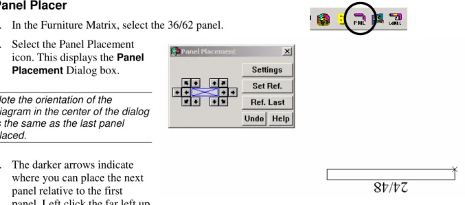
Panel Placer
1. In the Furniture Matrix, select the 36/62 panel. 2. Select the Panel Placement
icon. This displays the Panel Placement Dialog box. Note the orientation of the
diagram in the center of the dialog is the same as the last panel placed.
3. The darker arrows indicate where you can place the next panel relative to the first panel. Left click the far left up
arrow to snap a vertically positioned panel attached to the first panel.
4. Select and place the following panels, working clockwise: (2) 42 x 62 to create a 90 degree corner; (3) 30x62 to the right, (2) 42x62 to form a 90 degree corner, (1) 36 x 62 going down, (1) 24 x 48 to the left. See layout below.
5. If you make an error, left click the Undo button in the Panel Placement dialog box - NOT the Undo icon on the toolbar.
Changing the Panel Reference
1. If you need to change which panel you are working with, left click the Set Ref button. Place the cursor on the panel you need to reference in the drawing and left click once.
Note: The panel you just left clicked is now highlighted. This is a visual aid letting you know when you place the next panel using the dialog direction arrows, it will snap to the highlighted panel. 2. The Ref. Last button will automatically highlight the last panel placed in the project. 3. Using the panel system you just completed,open the Panel Placement dialog box. 4. Left click the Set Ref. Button.
5. Bring the cursor over the upper right vertical 42 x 62 panel.
6. Left click once to highlight the panel and set that panel as the referenced panel.
7. Left click the upper right arrow to place a panel making a 3-way connection. Notice the spacing is correct for a 3-way connector.
Placing Worksurfaces
When placing worksurfaces, the crosshairs will be on the back corner of the worksurface. Be sure that the back of the worksurface is attaching to the panel.
1. Left click the WkSurfaces tab on the Furniture Icon Menu, then select w/o KB (without keyboard), and select a 36x24 rectangular
worksurface.
2. Bring the cursor into the drawing area. An outline of the worksurface is attached to the cursor.
3. Use the arrow keys on the keyboard to rotate the worksurface.
Note: if the symbol will not rotate, select it again from the menu.
4. Bring the worksurface close to, but not
touching, the corner created by the panels in the lower left.
5. Right click to snap it to the panels. If you have the symbol too close to the panels, it may snap to the wrong side of a panel. Make sure you place the worksurface correctly before continuing.
6. Continue placing additional worksurfaces in the same manner, with a 42” corner worksurface in each corner and a 30 x 72 peninsula attached to the 30” panel as shown below.
Placing Overhead Storage
When placing overheads you need to investigate each product line as each manufacture inserts the overhead at different elevations. Generally the insertion point for the overheads is at the top left corner of the back of the cabinet. The following steps set your drawing up to place the overheads at the appropriate location.
1. On the Furniture Icon Menu, left click the System Furn Tab. 2. Leftclick the FD Cab icon.
3. Select the 13” X 36” flipper.
4. In order to place the overhead cabinet at the proper height, you must set the furniture elevation Z-height. Just to the right of the drawing toolbar is the following:
5. Each of these selections has a radio button in front of them. Left click on the radio button in front of Z Ht.
6. In the field box to the right of Z-height type in or use the increment arrows to enter the desired Z-height.
10. On the tool bar left click the Activate 3D Window icon to see that the flipper has placed at the proper height.
11. Left click on the Create Hidden Line button to hide lines.
12. Left click the Activate 2D Window icon to return to the 2D view.
Note: Be sure to change the Z height back to Norm after inserting overheads, otherwise any items that you place after making this change will come in 62” above the floor.
Create Hidden Line Activate 3D Window Activate 2D Window
Placing Furniture at Specific Angles
Using the Work Angle command used earlier to draw walls, furniture can also be placed at angles:
1. Left click the Work Angle icon.
2. In the Work Angle dialog, enter the angle in the Work Angle field. 3. If the angle is unknown, left click the Selectan element... icon
(small
e
).4. Left click on the angled wall to calculate the angle. The angle is automatically entered in the Work Angle field.
5. Ensure there is a checkmark in Use work angle.
6. Left click OK.
7. Choose a furniture symbol. Note it is set to the same angle as the wall that was left clicked. The symbol will also rotate at this angle.
8. Place the symbol as normal.
9. When done placing symbols at this angle, left click the Work Angle icon to stop the command.
Changing the Height of a Symbol
In this example, we will lower the 36” worksurfaces from the preset height of 29” to a typing height of 27”.
1. Right click on the symbol.
2. Hold down the CTRL key and left click on each of the worksurfaces so they are all highlighted.
3. Right click on any red line, then choose Elevate from the edit menu.
4. The New Z-height Input dialog box opens.
5. To move the symbols up, enter positive numbers. The increment arrows can also be used. Worksurfaces will insert at standard worksurface height and must be moved in relationship to their default insertion point.
6. To lower the symbols enter negative numbers. Use the inch down increment arrow to enter -2”.
Placing Pedestals
1. In the System Furniture tab, left click on the pedestal icon.
2. From the furniture matrix, select a 20”, box, box, file pedestal (BBF).
3. You will notice that the cursor is attached to the front of the pedestal. This gives you the ability to snap the front of the pedestal to the front edge of the work surface.
4. Bring the pedestal to the 30”x24” worksurface located to the left of the peninsula. Move it onto position about where it should be installed.
5. Right click to snap the pedestal into place.
6. Place three more pedestals: one under the opposite 30”x24” worksurface, and one under each 36”x24” worksurface.
Placing Chairs
1. Left click on the System Furniture tab. 2. Left click on the chairs icon.
3. From the furniture matrix, left click on the Exec chair. 4. You will notice that the cursor is in the middle of the chair.
5. Use the keyboard’s left and right arrow keys to rotate the front of the chair parallel to the front edge of the corner
worksurface.
Select Symbols Search Function – Exact Part Number
The select symbol feature allows for placement of product based on their complete part number if they are in the current library. To utilize this feature:
1. Left click the Select Symbolsicon.
2. Enter a part number in the Style/Part Numberfield. 3. Once it has located the product, a graphic preview
will be shown.
4. Left click on the Place button and the item will be on the crosshairs in the drawing window.
Select Symbols Search Function – Partial Part Numbers
The select symbol feature allows for placement of product based on their partial part number or a part description. To utilize this feature:
1. Left click the Select Symbolsicon.
2. In the Place by Part Number dialog box choose the More
button. A different dialog box will appear.
3. Enter a partial part number or a portion of a part description to search and add on an asterisk (*).
4. Choose whether to search the Part No. field or the Part Description field.
5. Under the search results window is the Product Lines to Search choose the Current Manufacturer, the loaded manufacturers, or Allto search all installed libraries. 6. Left click the Searchbutton.
7. A list of all product codes that begin with letters/numbers entered appears in the bottom window.
8. Left click on the part number to be placed, then left click the Placebutton to continue placing the symbol in the drawing.
Moving or Copying a Single Item
1. Select the symbol that is to be moved right click on a red line. 2. In the Edit Menu, left click Move>Move or Copy>Copy. 3. The Symbol will be picked up by crosshairs.
4. Use arrow keys as if placing symbol for the first time to rotate the symbol, if necessary 5. Left click to place the symbol again.
Moving Multiple Items
1. After selecting the symbols to move, place the cursor on one of the highlighted lines and
right click.
2. In the Edit Menu, left click Move, then left click Move.
3. The status bar shows the program needs a Reference Point for Move.
4. Place the center of the crosshair cursor at the point you want to set as the reference. 5. Right click to set the reference or left click if you do not want to snap.
6. Place the cursor in a new location and left click to perform the move.
Moving a Measured Distance
1. After selecting the symbols to move, place the cursor on one of the highlighted lines and
right click.
2. In the Edit menu left click Move, then left click Move Dialog
3. In the X setting is where you would enter the distance you want to move left or right. In the Y setting enter the distance to move up or down. 4. Direction arrows are located to the right of these boxes - to change the
5. Once the distance to move has been entered and the direction arrows are pointing correctly, left click on Perform Move.
Note: You can enter both an X and a Y distance.
6. The selected symbols will automatically move the distance(s) entered.
2 Point Move
Two point move allows object to be moved a specified distance from a referenced point. 1. Select items to be moved.
2. Right click on any highlighted line to open the Edit menu. 3. Left click Move, then left click Move Dialog
4. Enter an X distance and Y distance for the move.
5. Verify the directional arrows are pointing the correct direction. 6. Place a check in the 2 point move check box
7. Left click Perform Move.
8. The status bar will ask for a reference point. You can right click on a point and the objects will move the specified distance from the point you select.
Note: If you don’t type an X or Y distance you will be prompted for a reference point and a new location. You can also change the rotation at that time.
Copying Multiple Items
1. Select the symbols to be copied.
2. Place the cursor on a highlighted line and right click.
3. On the Edit Menu, select Copy > Copy. 4. The status bar shows the program needs a
Reference Point for Duplicate.
5. Place the center of the crosshair cursor at the back of the left corner worksurface and right click to set the reference. This tells the program you want to snap the
6. Move the cursor to the far right side of the workstation, so the corner of the worksurface is near the panel that the corner worksurface would hang on and right click to snap.
7. You will get the message that duplicate panels exist. You will be prompted to make selection. Left click Delete Overlapping Panel(s).
Mirror
Mirror allows workstations to be placed back to back without duplicating panels. If a symbols is “handed” the software will automatically update the symbol with correct part number.
Mirror X
1. Select the symbols to be mirrored.
2. Place the cursor on a highlighted item and right click. 3. On the Edit menu, choose Mirror.
4. Select Mirror X.
5. In the status bar, the program is requesting Reference Point for Mirror Copy.
6. Right click to snap the first reference point. The first reference point for an X mirror will be the left side of a vertical panel.
7. The status bar now displays new location for reference point. The second point is the opposite side of the vertical panel. Essentially you will be making a mirrored copy of your worksurface and flipping it over the panel that you are choosing.
8. Move the cursor to the second
reference point and right click to snap to this point.
9. Click the Delete Overlapping Panel(s) button.
First Reference Point
Mirror Y
1. Right click on the selected furniture. 2. On the Edit menu, choose Mirror. 3. Select Mirror Y.
4. Right click to snap the first reference point.
5. The status bar now displays new location for reference point. The second point is the opposite side of
the vertical panel. Essentially you will be making a mirrored copy of your worksurface and flipping it over the panel that you are choosing.
6. Click the Delete Overlapping Panel(s) button. First Reference Point New Reference Point
Advanced Modification Tools
Move Rotate
Use this command to rotate or to rotate and move the symbol(s) at the same time: 1. Select the symbol(s) to be moved.
2. With the cursor on a highlighted line, right click and choose Move >Move Rotate. 3. Enter the degree for rotation and the direction for rotation in the rotate dialog box. 4. Left click Perform Edit.
5. Place the center of the crosshair cursor at the exact point on the selected symbol(s) to be referenced as the axis (the point the symbol(s) will rotate around). Right click
6. To rotate only - right click again at the same spot.
7. To move and rotate - move the cursor to the exact point on screen to move to (the first point selected will move to this point). Right click again to snap to an existing symbol, or left click once to move without snapping.
Copy Rotate
This function is performed the same as the Move Rotate, the only difference being the name of the command chosen from the Edit menu.
Align
The Align feature automatically aligns selected symbols with one left click of the mouse. For example, a row of chairs or desks can quickly be aligned by the front, rear, center or sides of the symbols.
1. Select the symbols to be aligned.
2. Right click on one of the selected chairs and choose Utilities > Align. 3. In the Align Elements dialog, left click on the alignment to be used.
Note: Multiple rows of items that are selected for alignment will be aligned to the same point. Align is best used for single items to be aligned rather than workstations.
Specialized Symbol Placement
The program will allow you to place symbols, typicals and columns in grid patterns. This is especially helpful when setting up a large seating arrangement or a classroom setting.
Grids
Single Symbol Placement
1. Select the symbol to be placed.
2. Left click Draw/Symbol Placement/Grid. 3. Place the first symbol as usual.
4. To place subsequent symbols, open the Point dialog and enter the
appropriate X and/or Y values. . For example, if you placed a chair and want to place each chair with a 1’ space between them and the chair is 2’ wide, enter an X value of 3’ 5. Ensure the directional arrow is pointing correctly.
6. Place a check in front of From a Fixed Point. 7. Left click Enter Point.
8. Right click at a point on the symbol that is already placed, in this case the insertion point of the chair.
9. In the Input dialog, enter the number of chairs to be placed per row. 10. Left click OK.
11. Now the program needs to know where to place the second row. Again, use the Point Input
12. Left click Enter Point.
13. Right click at a point on the symbol that is already placed, in this case the insertion point of the chair.
14. In the Input dialog, enter the number of rows to be placed. 15. Left click OK.
Note: Another way to perform this routine is to use the formula X, Y. Rather than using the Point dialog, simply place the first piece of furniture in the grid and type in the X (left or right) or Y (up or down) coordinates. X comes before the comma, and Y after. Remember to include width of each piece as you are measuring from center point to center point.
Placing Symbols at a Specific Location
1. To place a symbol at a specific location, first choose the symbol to be placed. In this
example, our desk will be placed 4” to the right and 4” down from the upper left-hand corner of the main room.
2. Because the Origin Point of the typical is on the interior of the upper left corner, this will leave 2” of space between the typical and the wall.
3. Select a desk from the furniture menu. 4. Left click the Point Input icon (white arrow
pointing to an X).
5. Enter 4” in the X field and make sure the arrow is pointing to the right.
6. Enter 4” in the Y field and make sure the arrow is pointing down.
7. Place a check in front of From Fixed point.
8. Left click Enter Point.
9. Bring the crosshair cursor just inside the upper left corner and right click to place the typical.
Creating Typicals
Rather than recreating this configuration from scratch every time it is needed in a project, GIZA can save it as a typical, which can then easily be reused and placed in many different drawings. To do this:
1. Select the entire workstation including the panels.
2. Place the cursor on a symbol in this configuration and right click. 3. In the Edit Menu select Utilities >
Make Typical.
4. In the Make Typical dialog box, type a name for the typical in the
File field box.
5. In the Make Typical From
section, choose Selected Elements.
6. The next step is to set an Origin Point. The Origin Point is the point in the typical where the cursor will be attached. This provides a visual reference when you place the typical.
7. In the Origin section, left click the radio button in front of Choose Point.
8. Left click the icon to the right of Choose Point (white arrow pointing to a blue circle).
9. Move the cursor into the drawing area. The cursor appears as a crosshair.
10. Place the center of the crosshairs inside of the panels at the upper left corner.
11. Right click to set the Origin Point.
When choosing the origin point for a typical it is important to consider how these typicals will be connecting to each other. The point selected should be at the corner of a worksurface where it attaches to a panel, usually a panel that will act as a spine wall.
Placing Typicals
1. To place a saved typical left click Draw/Typical on the Menu Bar. 2. The Place Typical dialog box appears.
Note: The name of the last typical saved shows in the dialog box. Left click the Browse button to find other typicals.
3. Left click on Place. The typical is now loaded onto your cursor as a blank box in the shape of your furniture. It is attached at the point you set as the Origin Point. The typical can be rotated using the arrow keys on the keyboard. The large X at the bottom left of the typical is a visual aid to help when you rotate the typical.
4. Position the typical on screen where you want to place it then left click to set it in the drawing.
Note: The cursor is the only active snapping point in the typical before you place it. Once placed, all the snapping points will become active
6. If you make a mistake, left click the Undo icon to erase the typical and try again. 7. If there are any overlapping panels, the Highlighted Overlapping Panel(s) dialog box
appears.
8. If you left click Delete Overlapping Panels, any duplicate, overlapped panels will be removed.
Placing Typicals on a Grid
1. To place a typical on a grid left click Draw > Typical on the Menu Bar.
2. Check the Grid button on the Draw Typical dialog. 3. Click Place for the first Typical.
4. Snap the next Typical by Rightclicking to the outside panel.
5. The Input dialog will pop up.
6. Enter the number of typicals you need in the row and pick OK.
7. You will be prompted to place the typical again for the next row placement. If you only want one row pick Stop or hit ESC. To place the next row use the Point Input tool. Add the width of the typical to the aisle size for your Y distance.
8. Select From Fixed Point and Enter Point. 9. Right Click the insertion point of the first typical. 10. Enter the number of rows you want and pick OK.
11. If there are any overlapping panels, the Highlighted Overlapping Panel(s) dialog box appears.
12. If you left click Delete Overlapping Panels, any duplicate, overlapped panels will be removed.