Zigbee-Based Wireless Distance Measuring Sensor
System
Ondrej Sajdl1, Jaromir Zak1, Radimir Vrba1
1 Department of Microelectronics, Brno University of Technology, FEEC,
Udolni 53, 602 00 Brno, Czech Republic [email protected]
Abstract. A cost effective ZigBee-based wireless parking sensor system is presented in this article. Ultrasonic transmitter and receiver are used for distance measurement. An evaluation, control and wireless data transfer are realized by one chip - Panasonic hybrid chip PAN4450 (8-bit microcontroller + IEEE 802.15.4 radio). System consists of four independent distance sensors and one central display and control unit.
Keywords: ZigBee, IEEE 802.15.4, sensor, wireless, parking system.
1 Introduction
Increasing numbers of the cars cause a decrease of parking places especially in larger cities. It becomes more and more difficult to find parking place. Car-parking is for many drivers an uneasy task and could be potentially danger. Car crashes are very common in connection with this maneuver. Car producers are aware of this situation and more expensive and luxurious new cars are equipped with parking system very often. But there is majority of older and cheap cars which do not have such system. It is possible to buy system additionally, but there are lots of problems with installation, especially where to pull cables, how to connect system to car battery, etc. This article describes a possible cost effective wireless solution of this problem.
2 Wireless Parking Sensor System
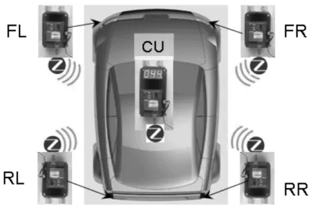
Our parking system consists of five independent units. Four intelligent distance meters are designated for car mount at usual positions: front left (FL), front right (FR), rear left (RL) and rear right (RR) part of car fender and one central unit (CU) inside car with a 7-segment display (see
Fig. 1. Wireless parking sensor system – a car with a four wireless ultrasound distance meters (FL, FR, RL, RR) and the one central unit (CU).
2.1 Sensor Units
The sensor unit is an intelligent sensor for distance measurement with a wireless interface. It is battery powered (9 V) and it is intended for placing into the car fender (see Fig. 2).
Fig. 2. Sensor unit prototype – an antenna is on the left side, a hybrid chip with MCU and radio is in the middle and a pair of ultrasound meters (receiver, transmitter) is on the right.
1. evaluation and control unit (8-bit microcontroller + software), 2. ultrasound distance meter,
3. IEEE 802.15.4 radio and antenna for wireless data transfer + software.
Evaluation and Control Unit. The heart of all units is a hybrid chip Panasonic PAN4450. It combines 8-bit Freescale HCS08 MCU and IEEE 802.15.4 radio chip Freescale MC13192. The MCU is internally connected to radio through SPI (Serial Peripheral Interface). The MCU contains all software for ultrasound distance measurement and a wireless communication driver based on a SMAC (see Wireless Data Transfer chapter). The hybrid chip, the antenna and the supporting circuits are located on a separate development board (our production) connected to other circuits (ultrasound distance meter) through a simple connector.
Ultrasound Distance Meter. The ultrasound distance measurement principle was chosen based on an extensive literature [3] [4] [5] and Internet search. We’ve investigated technologies like infrared light, laser, but we’ve found ultrasound as a good compromise between the cost versus the accuracy and reliability.
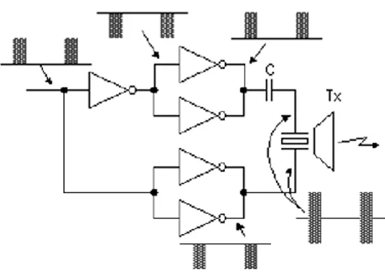
The distance meter is realized using an ultrasound transmitter-receiver pair and transmitter and receiver circuits. The transmitter sends periodically ultrasonic waves of 40 kHz for the 1 millisecond and pauses for the 62 milliseconds. The core of timing circuit is based on well-known IC NE555. The inverter is used for the drive of the ultrasonic sensor (see Fig. 3). The two inverters are connected in parallel because of the transmission electric power increase. The phase with the voltage to apply to the positive terminal and the negative terminal of the sensor has been 180 degrees shifted. It is because cutting the direct current with the capacitor, about twice of voltage of the inverter output are applied to the sensor.
Fig. 3. Ultrasonic sensor drive circuit
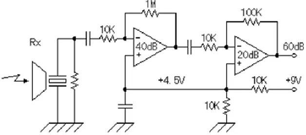
The ultrasonic signal that was returned from the measurement object and received with the reception sensor is 1000 times (60 dB) of voltage amplified with the operational amplifier with two stages. It is amplified 100 times at the first stage (40 dB) and 10 times (20 dB) at the next stage (see Fig. 4). The output of the detection
circuit is detected using the comparator. Signal is then converted into digital pulses using SR (the set and the reset) flip-flop. This circuit is the gate circuit to measure the time which is reflected with the measurement object and returns after sending out the ultrasonic wave. The set condition is the time which begins to let out the ultrasonic with the transmitter. It uses the transmission timing pulse. The reset condition is the time which detects the signal with the signal detector of the receiver circuit. That is, the time when the output of SR is in the ON condition and it becomes the time that returns after letting out the ultrasonic. Output of this SR is connected to MCU digital input. The MCU measures the duration of the pulses and computes the resulting distance.
Fig. 4. Receiver circuit – signal amplification
The distance is computed based on knowledge that the speed of sound is approximately 331 m/s. This speed depends on the temperature. However, an error of approximation causes an error in distance measurement for the small distances (tens of centimeters) in maximal range of 2 centimeters in positive and negative ranges for temperature range -10 to 10 °C (see Table 1).
Table 1. The speed of sound for each temperature [2]
Temperature [°C] Speed of sound [m/s]
-10 325.5
0 331.5
10 337.5
Our assumption is valid only for relatively small temperature ranges. It is true in the most European countries. However, this problem could be easily solved in next PCB version by adding a temperature sensor.
The distance is computed as follows:
2
331
t
d
, (1)where d is a distance in meters and t is a period in seconds between sending and receiving a pulse. The time must be divided by two because a reflected signal is measured.
Wireless Data Transfer. ZigBee is a new low rate wireless network standard designed for automation and control networks. The standard is aiming to be a low-cost, low-power solution for systems consisting of unsupervised groups of devices in houses, factories and offices. Expected applications for the ZigBee are building automation, security systems, remote control, remote meter reading and computer peripherals. In other words it is perfect for the presented application. A Bluetooth was also considered but it has too high power consumption and is not suitable for long-life battery powered systems. Physical radio (IEEE 802.15.4) is realized using Freescale MC13192 2.4 GHz low power transceiver.
A serious problem we’ve met was in the software – higher software layers of ZigBee stack are not free. The cost of ZigBee stack is a matter of thousands of dollars. But Freescale offers MAC (Medium Acces Control) layer software libraries for free. This software is called SMAC (Simple MAC). It contains API (Application Programming Interface) for complete control of MC13912 radio, including security.
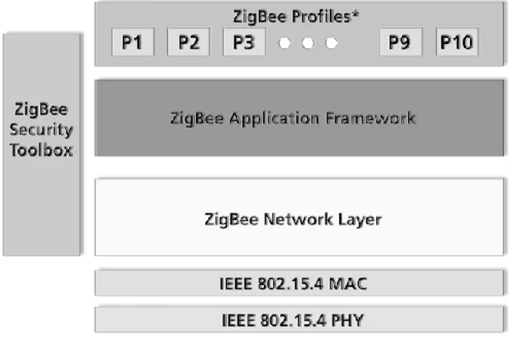
Our developed software based on SMAC allows half-duplex communication with central unit (star network topology) and handles sleep modes with time synchronization. The distance sensor units are periodically awakened and it waits for possible commands from the central unit. If there is no command in a certain time frame it falls asleep. Even though software development was the most time consuming task of the whole project, we are far from implementing all ZigBee higher layers. Nevertheless we do not need a full compatibility with ZigBee standard, our solution at this stage uses “only” physical radio layer according IEEE 802.15.4, MAC layer and proprietary network and application layer implementation based on SMAC (see
Fig. 5). ZigBee compatibility has sense when there is greater number of cheap standardized ZigBee devices on the market. For example we are considering possibility to use a smartphone or a personal digital assistant (PDA) instead central unit. But there are no such devices on the market at the present time.
Fig. 5. ZigBee stack [1] – our system has full physical radio layer, MAC layer and proprietary implemented network and application layer
2.2 Central Unit
The central unit is very similar to sensor unit except for missing ultrasonic circuits. Additionally it has 7-segment display for displaying measured distance. The display is connected directly to the MCU’s digital outputs; there are no additional circuits. The display is controlled directly by software driver stored in MCU. The central unit is also battery powered, but because of a high power consumption of a segment display it can be also connected to a car battery (12 V) through a car fuser. The display shows a value from one sensor unit and there is a button for units switching. However, the central unit receives the values from all sensor units and if the distance is smaller than predefined value (20 centimeters) the sound alarm is triggered.
A possible extension of the central unit could be taking advantage of programmable Bluetooth equipped devices - smartphones and PDAs. There is a plenty of such devices on the market and both are often used for car GPS navigation. In this case, the central unit is modified to simple ZigBee-Bluetooth converter so we can “make the best of both worlds” – ZigBee low power consumption and Bluetooth wide spread. The measurement, the alarms and the distance displaying could be solved by software on a Bluetooth device side.
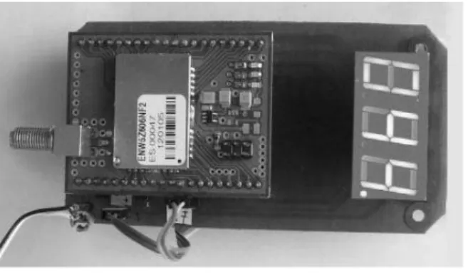
Fig. 6. Central unit prototype – similar to sensor unit with segment display; it doesn’t have ultrasound circuits.
3 Conclusion
It has been presented the original design of the low power wireless parking sensor system with an extremely reduced cost. It is reliable system with quick and easy installation. The system might be easily extended. Planned support of ZigBee certified and Bluetooth equipped devices will extend system usability in future.
Acknowledgments. Research has been supported by Ministry of Education of the Czech Republic in the frame of Research Program MSM0021630503 MIKROSYN and by the Czech Science Foundation as the project GACR 102/05/0869
References
1. ZigBee Aliance: ZigBee specification.WWW: http://www.zigbee.org/
2. Wikipedia: Speed of Sound. WWW: http://en.wikipedia.org/wiki/Speed_of_sound 3. Ultrazvukový dálkoměr. A Radio (2001) 2- 5, ISSN 1212-1843.
4. Benet G.1; Blanes F.; Simo J.E.; Perez P.: Using infrared sensors for distance measurement in mobile robots. Robotics and Autonomous Systems, Volume 40, Number 4, (30 September 2002) 255-266
5. Meggitt, B. T.; Palmer, A. W.: Distance measurement using laser diodes. FOS, Volume 33 (1999) 21-31