Execution Investigation of Distribution Generation Scheme
Fed PMSM Drive through Fuel Cell Energy Source
1Boddeda Jagannadha Rao,2Mr. M.Vamsi Sree ,3Mr. Grandhi Ramu 1
M.Tech (Research scholar),2Assistant professor,3HOD In Dept. of Electrical & Electronics Engineering Chaitanya Institute of Science & Technology, Kakinada.
Abstract—
Distributed Generation (DG) is rising as a reasonable option when renewable or nonconventional vitality assets are accessible, for example, wind turbines, photovoltaic clusters, power devices, small scale turbines. A large portion of these assets are joined with the utility through force electronic interfacing converters, i.e., three-stage inverter. DG is a suitable structure to offer high dependable electrical power supply, as it can work either in the grid tied mode or in the islanded mode. In the framework tied operation, DG conveyances energy to the utility and the neighborhood basic burden. The proposed control system makes out of an inward inductor current circle, and a novel voltage circle in the synchronous reference outline. The inverter is managed as a present source just by the inward inductor current circle in lattice tied operation, and the voltage controller is consequently initiated to direct the heap voltage upon the event of islanding. Moreover, the waveforms of the framework current in the lattice tied mode and the heap voltage in the islanding mode are mutilated under nonlinear neighborhood load with the customary procedure. his paper shows a bound together control methodology that empowers both islanded and framework tied operations of three-stage inverter in distributed generation, with no requirement for exchanging between two relating controllers or basic islanding identification utilizing mat lab/Simulink stage.
Index Terms— Unified Power Quality Conditioner, Three Phase Inverter, Distributed generation (DG), islanding, load current, seamless transfer.
I. Introduction
The late patterns in little scale power era utilizing the with the expanded worries on environment and expense of vitality, the force business is encountering central changes with more renewable vitality sources (RESs) or smaller scale sources, for example, photovoltaic cells, little wind turbines, and miniaturized scale turbines being coordinated into the force matrix as distributed generation (DG). The power devices are electrochemical gadgets that change over concoction vitality specifically into
determined in universal norms and rules. Inverters for the most part work with current control and solidarity force component and utilize detached checking for islanding recognition strategies in view of privately measured parameters. Under islanding conditions, the extent and recurrence of the voltage at the purpose of normal coupling (PCC) tend to float from the evaluated lattice values as a component of the force
lopsidedness (ΔP and ΔQ). As it is realized that
circulation framework does not have any dynamic force creating source and does not get power in the event of a shortcoming in transmission line. The guideline incorporates as the quantity of levels in the inverter builds, the yield voltage has more step era i.e. staircase waveform, which has a decreased symphonious twisting. The fundamental hindrance of number of levels incorporates more number of exchanging gadgets, diodes, and other detached components. Thus inverter gets to be massive, more control many-sided quality and presents voltage-unevenness. To tackle the above issue, a hilter kilter topology H-span inverter with three unequal DC sources is utilized. This topology has the ability of using distinctive DC voltages on the individual H-span cells.
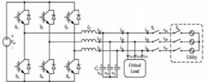
Fig. 1. Schematic diagram of the DG based on the proposed control strategy.
The standard incorporates as the quantity of levels in the inverter expands, the yield voltage has more step era i.e. staircase waveform, which has a decreased symphonious bending. The fundamental inconvenience of number of levels incorporates more number of exchanging gadgets, diodes, and other detached components. Subsequently inverter gets to be massive, more control multifaceted nature and presents voltage-awkwardness. To tackle the above issue, an uneven topology H-span inverter with three unequal DC sources is utilized. This topology has the capacity of using diverse DC voltages on the individual H-span cells. A. Uninvolved routines this system is quick to identify the islanding. In any case, it has vast non-location zone and it need unique consideration to set the limits for it is parameters. Detached technique can characterized into: Rate of progress of yield force, Rate of progress of recurrence, rate of progress of recurrence over force, Change of impedance, voltage unbalance, and symphonious bending B. Dynamic Methods Active
system tries to conquer the weaknesses of inactive routines by presenting irritations in the inverter yield. Dynamic strategy can identify the islanding even under the ideal match of era and burden, which is unrealistic if there should be an occurrence of the detached identification conspires yet it brought about debasement of force quality. Dynamic system can be characterized into: Reactive force trade blunder recognition, Impedance estimation strategy, Phase (or recurrence) shift techniques, Active Frequency Drift, Active Frequency Drift with Positive Feedback Method, Adaptive Logic Phase Shift, and Current infusion with positive criticism. C. Half and half Methods Hybrid system in view of actualizing of two variety of dynamic and inactive technique. The dynamic procedure is executed just when the islanding is suspected by the latent system. It can be grouped into: Technique in light of voltage and receptive force shift, Technique in view of positive criticism and voltage lopsidedness In current into the utility for alleviating the symphonious part of the framework current, is exhibited in [41]. General, once the fundamental framework source supply is lost the DG needs to assume responsibility of the remaining system and the joined burdens. Aloof location plan, then again, screens parameters for distinguishing the islanding operations of DG: voltage unbalance, recurrence, dynamic and receptive force alongside aggregate consonant contortion (THD). In the half and half voltage and current mode control, there is a need to switch the controller when the operation method of DG is changed. Amid the interim from the event of utility blackout and changing the controller to voltage mode, the heap voltage is neither altered by the utility, nor managed by the DG, and the length of the time interim is dictated by the islanding recognition process. Along these lines, the principle issue in this methodology is that it makes the nature of the heap voltage intensely dependent on the pace and precision of the islanding location system [6]–[10]. Another issue connected with the previously stated methodologies is the waveform nature of the matrix current and the heap voltage under nonlinear nearby
II. Proposed Control Strategy
D. Power Stage This paper presents a unified control strategy for a three phase inverter in DG to operate in both islanded and grid-tied modes. The schematic diagram of the DG based on the proposed control strategy is shown by Fig. 1. The DG is equipped with a three-phase interface inverter terminated with a LC filter. The primary energy is converted to the electrical energy, which is then converted to dc by the front-end power converter, and the output dc voltage is regulated by it. Therefore, they can be represented by the dc voltage source Vdc in Fig. 1. In the ac side of inverter, the local critical load is connected directly. It should be noted that there are two switches, denoted by Su and Si , respectively, in Fig. 1, and their functions are different. The inverter transfer switch Si is controlled by the DG, and the utility protection switch Su is governed by the utility. When the utility is normal, both switches Si and Su are ON, and the DG in the grid-tied mode injects power to the utility. When the utility is in fault, the switch Su is tripped by the utility instantly, and then the islanding is formed. After the islanding has been confirmed by the DG with the islanding detection scheme [6]–[10], the switch Si is disconnected, and the DG is transferred from the grid-tied mode to the islanded mode. When the utility is restored, the DG should be resynchronized with the utility first, and then the switch S I is turned ON to connect the DG with the grid . B. Basic Idea With the hybrid voltage and current mode control [17]–[40], the inverter is controlled as a current source to generate the reference power PDG+jQDG in the grid-tied mode. And its output power PDG+jQDG should be the sum of the power injected to the grid Pg +jQg and the load demand P load + jQ load, which can be expressed as follows by assuming that the load is represented as a
parallel RLC circuit: (1) (2) In (1) and (2), Vmandω
represent the amplitude and frequency of the load voltage, respectively. When the nonlinear local load is fed, it can still be equivalent to the parallel RLC circuit by just taking account of the fundamental component. During the time interval from the instant of islanding happening to the moment of switching the control system to voltage mode control, the load voltage is neither fixed by the utility nor regulated by the inverter, so the load voltage may drift from the normal range [6]. And this phenomenon can be explained as below by the power relationship. During this time interval, the inverter is still controlled as a current source, and its output power is kept almost unchanged.
However, the power injected to utility decreases to zero rapidly, and then the power consumed by the load will be imposed to the output power of DG. If both active power Pg and reactive power Qg injected into the grid are positive in the grid-tied mode, then P load and Q load will increase after the islanding happens, and the amplitude and frequency of the load voltage will rise and drop, respectively, according to (1) and (2) With the previous analysis, if the output power of inverter PDG+jQDG could be regulated to match the load demand by changing the current reference before the islanding is confirmed, the load voltage excursion will be mitigated. And this basic idea is utilized in this paper. In the proposed control strategy, the output power of the inverter is always controlled by regulating the three-phase inductor current iLabc, while the magnitude and frequency of the load voltage vCabc are monitored. When the islanding happens, the magnitude and frequency of the load voltage may drift from the normal range, and then they are controlled to recover to the normal range automatically by regulating the output power of the inverter. C. Control Scheme Fig. 2 describes the overall block diagram for the proposed unified control strategy, where the inductor current iLabc ,the utility voltage vg abc, the load voltage vCabc, and the load current iLLabc are sensed. And the three-phase inverter is controlled in the SRF, in which, three phase variable will be represented by dc quantity. The control diagram is mainly composed by the inductor current loop, the PLL, and the current reference generation module. In the inductor current loop, the PI compensator is employed in both D- and Q-axes, and a decoupling of the cross coupling
denoted byω0Lf/k PWM is implemented in order to
mitigate the couplings due to the inductor. The output of the inner current loop dd q , together with the decoupling of the capacitor voltage denoted by 1/k PWM, sets the reference for the standard space vector modulation that controls the switches of the three-phase inverter. It should be noted that k PWM denotes the voltage gain of the inverter, which equals to half of the dc voltage in this paper.
Fig. 3. Block diagram of the current reference generation module
phase. Furthermore, a limiter is inserted between the PI compensator GPL Land the integrator, in order to hold the frequency of the load voltage within the normal range in the islanded operation. In Fig. 2, it can be found that the inductor current is regulated to follow the current reference iLrefdq, and the phase of the current is synchronized to the grid voltage vgabc. If the current reference is constant, the inverter is just controlled to be a current source, which is the same with the traditional grid-tied inverter. The new part in this paper is the current reference generation module shown in Fig. 2, which regulates the current reference to guarantee the power match between the DG and the local load and enables the DG to operate in the islanded mode. Moreover, the unified load current feed forward, to deal with the nonlinear local load, is also implemented in this module. The block diagram of the proposed current reference generation module is shown in Fig. 3, which provides the current reference for the inner current loop in both grid-tied and islanded modes. In this module, it can be found that an unsymmetrical structure is used in D- and Q-axes. The PI compensator is adopted in D-axes, while the P compensator is employed in Q-axis. Besides, an extra limiter is added in the D-axis. Moreover, the load current feed forward is implemented by adding the load current iLLdq to the final inductor current reference iLrefdq. The benefit brought by the unique structure in Fig. 3 can be represented by two parts: 1) seamless transfer capability without critical islanding detection; and 2) power quality improvement in both grid-tied and islanded operations. The current reference iLredq composes of four parts in D-and Q-axes respectively: 1) the output of voltage controller irefdq; 2) the grid current reference Igrefdq; 3) the load current iLLdq; and 4) the current flowing through the filter capacitor Cf . In the grid-tied mode, the load voltage vCdq is clamped by the utility. The current reference is irrelevant to the load voltage, due to the saturation of the PI compensator in D-axis, and the output of the P compensator being zero in Q-axis, and thus, the inverter operates as a current source. Upon occurrence of islanding, the e voltage by regulating the current reference, and the inverter acts as a voltage source to supply stable voltage to the local load; this relieves the need for switching between different control architectures. Another distinguished function of the current reference generation module is the load current feed forward. The sensed load current is added as a part of the inductor current reference iLrefdq to compensate the harmonic component in the grid current under nonlinear local load. In the islanded mode, the load current feed forward operates still, and the disturbance from the load current, caused by the nonlinear load, can be suppressed by the fast inner
inductor current loop, and thus, the quality of the load voltage is improved. The inductor current control in Fig. 2 was proposed in previous publications for grid-tied operation of DG, and the motivation of this paper is to propose a unified control strategy for DG in both grid-tied and islanded modes, which is represented by the current reference generation module in Fig. 3. The contribution of this module can be summarized in two aspects. First, by introducing PI compensator and P compensator in D-axis and Q-axis respectively, the voltage controller is in activated in the grid-tied mode and can be automatically activated upon occurrence of islanding. Therefore, there is no need for switching different controllers or critical islanding detection, and the quality of the load voltage during the transition from the grid-tied mode to the islanded mode can be improved. The second contribution of this module is to present the load current feed forward to deal with the issue caused by the nonlinear local load, with which, not only the waveform of the grid current in grid-tied is improved, but also the quality of the load voltage in the islanded mode is enhanced. Besides, it should be noted that a three-phase unbalanced local load cannot be fed by the DG with the proposed control strategy, because there is no flow path for the zero sequence current of the unbalanced load, and the regulation of the zero sequence current is beyond the scope of the proposed control strategy.
III. Operating Principle Of Dg
The operation principle of DG with the proposed unified control strategy will be illustrated in detail in this section, and there are in total four states for the DG, including the grid-tied mode, transition from the grid-tied mode to the islanded mode, the islanded mode, and transition from the islanded mode to the grid-tied mode. A. Grid-Tied Mode When the utility is normal, the DG is controlled as a current source to supply given active and reactive power by the inductor current loop, and the active and reactive power can be given by the current reference of D-and Q-axis independently. First, the phase angle of the utility voltage is obtained by the PLL, which consists of a Park transformation expressed by (3), a PI compensator, a limiter, and an integrator
voltage references in D and Q-axis are Vmax and zero, respectively. And the magnitude of the load voltage equals to Vmax approximately, which will be analyzed in Section IV. Consequently, the control diagram of the three-phase inverter in the islanded mode can be simplified as shown in Fig. 4. In Fig. 4, the load current iLLdq is partial reference of the inductor current loop. So, if there is disturbance in the load current, it will be suppressed quickly by the inductor current loop, and a stiff load voltage can be achieved.
Fig. 4. Simplified block diagram of the unified control strategy when DG operates in the islanded mode.
IV. Analysis & Design
In this section, the three-phase inverter with the proposed control strategy is analyzed and designed in both steady state and transient state. In the steady state, the operation points of DG in both grid-tied and islanded modes are analyzed, and the limiters and references are selected. In the transient state, compensators in both inductor current loop and the external voltage loop are designed based on the small-signal model, and the impact of the load current feed forward is analyzed as well.
A. Steady State
1) Analysis of Operation Points: As analyzed previously, in the grid-tied mode, the inverter is controlled as a current source, and the current reference for the inductor current loop iLrefdq is expressed by (6) and (7). The steady-state error will be zero with the PI compensator in the inductor current loop, so the inductor current in steady state can be expressed as follows:
In the SRF, the relationship between the voltage and the current of the filter capacitor in steady state can be expressed by
Where ω represents the angle frequency of the DG
and Cf denotes capacitance of the filter capacitor. As a result, the
the load current iLLdq, as vCq equals zero in the
grid-tied mode. The active and reactive power injected into utility can be obtained as follows. Consequently, the active power and reactive power flowing from the inverter to utility can be given by Igref d and gref q, respectively
In the islanded mode, the inverter is controlled as a voltage source by the external voltage loop. In the D-axis,vCdis regulated by the PI compensator GVD, so
the steady state error will be zero and vCdcan be
expressed as follows:
Where Vref is the voltage reference inD-axis. In the
Q-axis, the regulator GVQ is P compensator, so the steady state error may not be zero. As the load current is added to the inductor reference, the condition shown as below can be achieved
And then, the load voltage inQ-axis can be expressed. It should be noted that the absolute value of vCqrises
with the increase of the current reference Igrefq which is related to the reactive power injected into the utility
.
output current of the inverter
i
o
dq can be gained
As anglefrequencyω is very closeto theratedAngle
frequencyω0, the output current
i
odq can be simplified as
The magnitude of the load voltage Vm can be represented as follows. It equals to Vref approximately, because vCq should be much lower than Vref with proper current reference Igrefq The voltage loop just operates in the islanded mode to regulate the load voltage, and the simplified block diagram is shown in Fig. 8, where Gic(s) and Gvi(s) denote the closed loop transfer function of an inductor loop and the impedance of the filter capacitor Cf, respectively.
In the D-axis, GVD is a PI compensator shown in (32), while a P compensator GVQ expressed by (33) is used in Q-axis. These two compensators are designed, and the loop gain of the current loop is shown in Fig. 11. It can be found that there is a little difference in the low frequency range. The phase margin is set to 55◦ , and the crossover frequency is
around 600 Hz in
Fig. 5. Block diagram of the simplified voltage loop. 4) Impact of Load Current Feed forward:
In Fig. 8, the load currentˆ iLL is a part of the
inductor current reference, and the disturbance from the load current can be suppressed by the inductor current loop directly. To evaluate the effect of the load current feed forward in the islanded mode, the transfer function of the output impedance is derived. The output impedances with and without load current
When the islanding happens, the angle frequency is restricted in the given range by the limiter. As analyzed previously, the angle frequency in the islanded mode is determined in the first time interval of the transition from the grid-tied made to the islanded mode. According to (20), if the current reference Igref q is set to zero, vCq is zero. Then, it means that the angle frequency ω does not vary in the
first time interval of the transition, and it should
equal ωg0, which denotes the angle frequency of the utility before islanding happens. Consequently, the
angle frequency of the load voltage ω in the islanded mode is determined by the current reference Igref q, and it can be expressed by (22),
Where ω min and ω max represent the upper and
lower values of the limiter shown in Fig. 2, respectively
the maximum magnitude of the utility voltage in this paper. According to IEEE standard 1547-2003 [5], the range of the normal grid voltage is 0.88–1.1 p.u., so Vmax can be selected as
Where Vn represents the RMS value of the rated phase voltage. In order to guarantee that the PLL operates normally in the
grid-tied mode, the utility angle frequency ω should not touch the upper value ω max or lower value ω
min of the limier in the PLL. Besides, the angle
frequency ω is restricted between ω max and ω min
in the islanded mode, and it should not drift from the normal value too far. So, ω max and ω min are
selected as the maximum and minimum angle frequencies allowed by the utility standard.
B. Transient State
1) Small-Signal Model of the Power Stage: Before the compensators in the voltage and current loops are designed and the transient performance is analyzed, the three-phase inverter in the DG needs to be modeled. According to the power stage shown in Fig. 1, the dc-link voltage Vdc is regulated by the front-end converter in DG. Then, it is assumed that the dc voltage Vdc is very stiff, and its dynamic is not concerned in this paper.
V. Matlab/Modeling & Results
Here simulation is carried out in different cases, in that 1). Proposed Three Phase Three level Inverter Fed Distributed Generation Scheme using Unified Control Scheme. 2). Proposed Inverter Fed Distributed Generation Scheme with Fuel Energy system Fed PMSM Drive Case 1: Proposed Three Phase Three level Inverter Fed Distributed Generation Scheme using Unified Control Scheme
Fig.7. Simulation waveforms of load voltage vCa , grid current iga, and inductor current iLa when DG is in the gridtied mode under condition of the step down of the grid current reference from 9 A to 5 A with proposed unified control strategy
Fig.8 Simulation waveforms under DG is transferred from the islanded mode to the grid-tied mode, grid voltage vga ,& load voltage vC a , as well as grid current iga& inductor current iLa
Case 2: Proposed Inverter Fed Distributed Generation Scheme with Fuel Energy system Fed PMSM Drive
Fig.9Matlab/Simulink Model of Proposed Inverter Fed Distributed Generation Scheme with Fuel Energy system Fed PMSM Drive using Matlab/Simulink platform.
Fig.10 shows the Speed, Active Power, Line Currents of PMSM, Injected Power in Quadrature axis of
Proposed Inverter Fed Distributed Generation Scheme with Fuel Energy system Fed PMSM Drive
Fig.11 DC Link Voltage, Line Currents, Power Factor of Proposed Inverter Fed Distributed Generation Scheme with Fuel Energy system Fed PMSM Drive.
VI. Conclusion
Distributed power also offers increased reliability, uninterruptible service, and energy cost savings. In general, the energy source in a distributed power scheme is a fuel cell, a micro turbine, or a photo-voltaic cell. A novel advanced voltage controller was presented. It is inactivated in the grid tied mode, and the DG operates as a current source with fast dynamic performance. Upon the utility outage, the voltage controller can automatically be activated to regulate the load voltage. Moreover, a novel load current feed forward was proposed, and it can improve the waveform quality of both the grid current in the grid-tied mode and the load voltage in the islanded mode. A advanced control strategy was proposed for three-phase inverter in DG to operate in both islanded and grid-tied modes, with no need for switching between two different control architectures or critical islanding detection. The proposed converter strategy is applied to PMSM drive to check the performance characteristics of the drive application.
References
[1] R. C. Dugan and T. E. McDermott, “Distributed generation,” IEEE Ind. Appl. Mag., vol. 8, no. 2, pp. 19–25, Mar./Apr. 2002.
[2] R. H. Lasseter, “Microgrids and distributed generation,” J. Energy Eng., vol. 133, no. 3, pp. 144–
149, Sep. 2007.
[4] IEEE Recommended Practice for Utility Interface of Photovoltaic(PV) Systems, IEEE Standard 929-2000, 2000.
[5] IEEE Standard for Interconnecting Distributed Resources with Electric Power Systems, IEEE Standard 1547-2003, 2003.
[6] J. Stevens, R. Bonn, J. Ginn, and S. Gonzalez, Development and Testing of an Approach to Anti-Islanding in Utility-Interconnected Photovoltaic Systems. Livermore, CA, USA: Sandia National Laboratories, 2000.
[7] A. M. Massoud, K. H. Ahmed, S. J. Finney, and
B. W. Williams, “Harmonic distortion based island
detection technique for inverter-based distributed
generation,” IET Renewable Power Gener., vol. 3,
no. 4, pp. 493–507, Dec. 2009.
[8] T. Thacker, R. Burgos, F. Wang, and D.
Boroyevich, “Single-phase islanding detection based on phase-locked loop stability,” inProc. 1st IEEE
Energy Convers. Congr. Expo., San Jose, CA, USA, 2009, pp. 3371–3377.
[9] K. Kim, J.-H. Jeon, J.-B. Ahn, B. Lee, and
S.-H. Kwon, “Frequency shift acceleration control for anti-islanding of a distributed-generation inverter,”
IEEE Trans. Ind. Electron., vol. 57, no. 2, pp. 494–
504, Feb. 2010.
[10] A. Yafaoui, B. Wu, and S. Kouro, “Improved
active frequency drift anti islanding detection method for grid connected photovoltaic systems,” IEEE
Trans. Power Electron., vol. 27, no. 5, pp. 2367–
2375, May 2012
Authors:
Mr. Boddeda
Jagannadha Rao received the
Bachelor of Engineering degree in Electrical & Electronics Engineering from Visakha Institute Of Science And Technology, Sontyam, Visakhapatnam from JNTU Kakinada in 2012. Currently he is pursuing master of technology in Chaitanya Institute of Science & Technology, Kakinada, A.P. His areas of interests are in Electrical Circuits, Control systems, Power Systems, Power Electronics and Electrical Machinery Modeling Analysis, Electrical Machines.
Mr. M.Vamsi Sree received the
Bachelor of Engineering degree in Electrical & Electronics Engineering from BVCE, Amalapuram from JNTU Kakinada in 2008. He received master of technology from Sri Vasavi Engineering College, Tadepalligudem in 2012, A.P. He is currently working as assistant professor in Chaitanya Institute of Science & Technology, Kakinada, A.P. His areas of interests are in Power Systems, Power Electronics, Electrical Machines and FACTS.