DAMAGE MORPHOLOGICAL PARAMETERS
J
EAN-L
OUISC
HERMANT, G
UILLAUMEB
OITIER, S
EVERINED
ARZENS, M
ICHELC
OSTERANDL
ILIANEC
HERMANTLERMAT, URA CNRS 1317, ISMRA, 6 Bd Maréchal Juin, 14050 Caen Cedex, France
(Accepted October 27, 2001)
ABSTRACT
This paper shows how it is possible to characterize and quantify the damages in materials using classical tools of automatic image analysis. Examples presented concern ceramic matrix composites, i.e. high tech materials. It gives important information to support the deformation and rupture mechanism of materials under mechanical solicitations.
Keywords: ceramic matrix composites, damage parameters, mathematical morphology.
INTRODUCTION
In many brittle materials, under a mechanical solicitation with or without temperature, many damages appear such as microcracks, grain or fiber/matrix decohesion, etc. If one can be able to quantify these damages, it could be a way to bring new material parameters to the mechanical engineers. For example for such materials one can use the damage mechanics, as proposed by Kachanov (1956), based on the decrease of the Young's modulus as the damages are in progress. But no morphological parameters of the damages are introduced in the formalism of the damage mechanics. The aim of this paper is to show how it is possible to use the classical methods of automatic image analysis to quantify the damages of some ceramic matrix composites during creep investigations.
MATERIALS AND METHODS
Materials investigated are CMCs, i.e. ceramic matrix composites, fabricated by SNECMA (Division Moteurs et Fusées, Saint-Médard en Jalles, France), according to a specific chemical vapor infiltration process into an architecture made of carbon or silicon carbide fibers (Christin et al., 1979; Naslain, 1999). That leads to Cf-SiC or SiCf-SiBC composites
depending on the chemical vapor content. These materials are in fact ceramic matrices reinforced by continuous ceramic fibers, for aeronautics and space applications (Lamicq, 1990; Spriet and Habarou, 1997).
Creep tests were performed in tension, under argon, at different stresses (up to 220 MPa) and temperatures
(up to 1673 K), using dogbone shaped specimens. Observations of damages were made through a scanning electron microscope, SEM (Jeol JSM 6400) or an optical microscope (Olympus BH2 type).
Automatic image analysis was performed either with a Matra Pericolor 3100 (Matra Cap System MS2I) or the Aphelion software from ADCIS. After the damage detection, classical tools of mathematical morphology (Serra, 1982; Coster and Chermant, 1985; 1989) were used in order to extract and quantify the correct damage features.
RESULTS
Two types of results on the damage quantification will be presented: the surface fraction of microcracks in crept Cf-SiC composites and the crack opening
evolution in crept SiCf-SiBC composites.
MICROCRACK SURFACE FRACTION
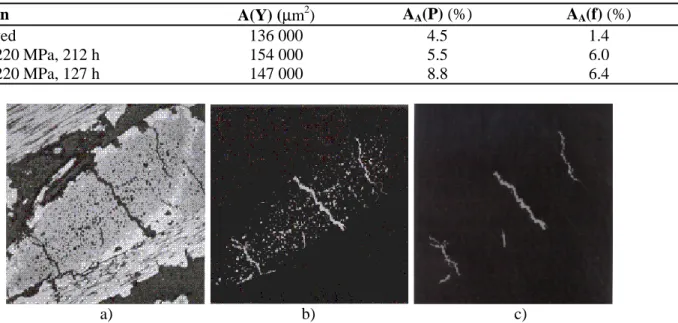
To extract the microcracks which have the same grey tone level than the pores, one successively uses several steps, but to be valid the frame of measurements must, of course, totally include the yarn to be analyzed to avoid any bias (Serra, 1982; Coster and Chermant, 1985; 1989): ① a threshold to extract microcracks + pores (Fig. 1b); ② the skeleton function to reduce microcracks and pores to the thickness of 1 pixel; ③ a clipping until the smallest skeletons which are related to the pores, will be lost; then ④ microcracks are reconstructed to obtain their initial sizes (Fig. 1c) and by difference between image ② and ④ one obtains the image of pores.
On these images we have measured the mean values of the surface area of the yarns, A(Y), the surface fraction of the intra-yarn pores, AA(P), and of
the microcracks, AA(f), in a 2.5D Cf-SiC in its
as-received state and after creep tests at 1273 K and 1673 K under 200 MPa. Values are given in Table 1.
One can note from such investigations that there
is a swelling of the yarns due to the development of the matrix microcracking process.
CRACK OPENING EVOLUTION
In the case of SiCf-SiBC, the matrix microcracks
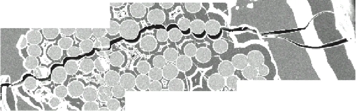
were followed, during creep and using step-creeping tests (Darzens, 2000), by the techniques of automatic image analysis as previously described. Then the maximum thicknesses of the microcracks were calculated from the greatest inscriptible square in the considered microcrack, without considering the pores when they are crossed by a microcrack. Fig. 2 illustrates that measurement.
During the loading the microcracks completely cross the inter-yarn zone perpendicular to the stress direction and reach the longitudinal yarns. Thereafter there is a deviation of the microcracks in mode II in the pyrolytic carbon layer parallel to the stress direction, and the opening of these microcracks is then very low. So the damage quantification was only undertaken in the transverse yarns. Fig. 3 presents the evolution of a transverse microcrack during different step-creeping tests at 1473 K, under 120 MPa.
One notices an increase of the opening of the microcracks during the creep process. Each given experimental result value (Fig. 3) is the mean for 35 microcrack measurements corresponding to 75 acquirements for each microcracks. The accuracy of measurements is 0.25 µm.
Table 1. Mean values of the surface area of yarns, A(Y), of the surface fraction of the intra-yarn pores, AA(P),
and of the microcracks, AA(f), in 2.5D Cf-SiC specimens, as-received and after tensile creep at 1273 K and
1673 K, at 220 MPa under argon.
Specimen A(Y) (µm2) AA(P) (%) AA(f) (%)
as-received 136 000 4.5 1.4
1273K, 220 MPa, 212 h 154 000 5.5 6.0
1673K, 220 MPa, 127 h 147 000 8.8 6.4
a) b) c)
Fig. 1. Image processing to investigate automatically the microcrack morphology of a 2.5D Cf-SiC, after creep
a) b)
Fig. 2. Measurement of the maximum width of a crack using a square structuring element in a SiCf-SiBC
composite, creep tested at 1473 K under 120 MPa, after 3 h (a) and 10 h (b).
t = 2 h, εin = 0.37%
t = 9 h 40 (rupture), εin = 0.63% t = 1 h, εin = 0.25%
20 µm
Fig. 3. Evolution of a transverse matrix microcrack in a N1 SiCf-SiBC composite, during the creep at 1473 K,
The number of analyzed microcracks is, of course, too low to have a result statistically representative of the microcrack array in the hot zone of the crept specimens. Nevertheless, it gives some correct information on the trends. After 50 h of creep, the mean crack opening is 5 times larger than after the loading. As the standard deviation values are low, these results appear homogeneous with regard to the crack opening.
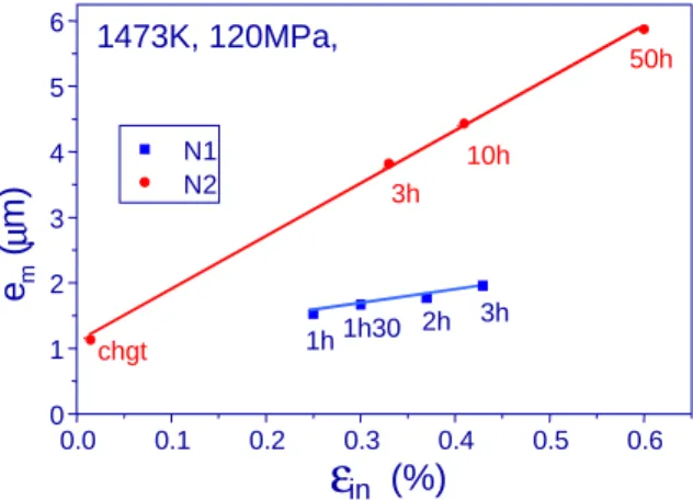
Fig. 4 shows the change of the microcrack opening, em, as a function of the inelastic strain, εin, for two
types of composites N1 and N2 SiCf-SiBC, after
creep tests at 1473 K under 120 MPa (the difference in N1 and N2 lies in the layer sequence; the inelastic strain corresponds to the total creep strain less the elastic strain calculated from the Hooke’s law). There is a linear dependence between em and εin. It appears
that for N2 composites the microcrack opening evolves more largely than for N1 composites, while the microcrack inter-distance remains similar: 650 µm and 610 µm, respectively for N1 and N2 composites.
0.0 0.1 0.2 0.3 0.4 0.5 0.6 0 1 2 3 4 5 6 (%) 1473K, 120MPa, 3h 2h 1h30 1h 50h 10h 3h chgt N1 N2 em (µ m)
ε
inFig. 4. Change in the microcrack opening, em, as a
function of the inelastic strain, εin, for N1 and N2
SiCf-SiBC composites, creep tested at 1473 K, under
120 MPa.
This difference informs on the existence of two different damage mechanisms which confirms the macroscopical and damage mechanics results (Darzens, 2000).
DISCUSSION
Although these morphological measurements are simple and classical, they bring very important information regarding the creep mechanisms.
It has been previously shown that damage creep is a possible mechanism for these CMCs when applied temperatures and stresses are not high enough to activate dislocation motions or/and diffusion
phenomena (Chermant, 1995; 2000). Several authors (Boitier et al., 1999; Darzens, 2000) have shown that there is ① first a rapid formation of a crack network until its saturation, and ② then another mechanism which appears very slow. Both the changes in the surface areas and microcrack openings of the matrix microcracks confirm that the second mechanism can be assimilated to a slow crack growth process, SCG, well known for glass and ceramic materials (Wierderhorn et al., 1968; Evans, 1972).
These damage morphological parameters are not the only ones, others can be also investigated such as the mean number of cracks per unit surface, the mean crack length per unit surface, the mean distance between cracks, their orientation, etc. Some of these parameters were investigated in the case of concrete materials by several authors (Ringot, 1988; Gérard et
al., 1996; Nemati et al., 1998; Ammouche et al., 1999; 2000).
CONCLUSION
This short paper has shown the importance of the morphological quantification of brittle damages in materials mechanically tested. It helps the mechanical engineers as it brings them morphological parameters of the damages in solicitated materials which have now to be introduced in the mathematical formalisms of the damage mechanics.
ACKNOWLEDGEMENTS
This work has been performed in the frame of the "Pôle Traitement et Analyse d'Images" (Image Processing and Analysis Pole) of Basse-Normandie (Pôle TAI). It has been supported by SNECMA, Division Moteurs et Fusées, St Médard en Jalles, France, and the CNRS for the ceramic matrix composite investigations. The authors thank the CNRS and Région of Basse-Normandie for the fellowships (GB and SD).
REFERENCES
Ammouche A (1999). Caractérisation automatique de la microfissuration des bétons par traitement d’images. Application à l’étude de différents faciès de dégradation. Thèse de Doctorat of the University of Bordeaux I, et Philisophiae Doctor of the University Laval-Québec. Ammouche A, Breysse D, Hornain H, Didry O, Marchand J
Boitier G, Chermant JL, Vicens J (1999). Multiscale investigation of the creep behavior of a 2.5D Cf-SiC
composites. J Mat Sci 34:1-9.
Chermant JL (1995). Creep behavior of ceramic matrix composites. Sil Ind 60:261-73.
Chermant JL (2000). Damage and creep of CMCs. Ceram Trans 103:409-27.
Christin F, Naslain R, Bernard C (1979). A thermodynamic and experimental approach of silicon carbide CVD. Application to the CVD-infiltration of porous carbon-carbon composites. In: Sedwick TO, Lydtin H, eds. Proceedings of the 7th International Conference on CVD. Princeton: The Electrochemical Society, 499-514. Coster M, Chermant JL (1985; 1989). Précis d'analyse
d'images. Les Editions du CNRS; 2nd edition, Les Presses du CNRS.
Darzens S (2000). Fluage en traction sous argon et microstructure de composites SiCf-SiBC. Thèse de
Doctorat of the University of Caen.
Evans AJ (1972). A method for evaluating the time-dependent failure characteristics of brittle materials, and its application to polycrystalline alumina. J Mat Sci 7:1137-46.
Gérard B, Breysse D, Ammouche A, Houdusse O, Didry O (1996). Cracking and permeability of concrete under tension. Mat Struct 29:141-51.
Kachanov L (1958). Rupture time under creep conditions. Izv Akad Nauk SSR 8:26-31.
Lamicq P (1990). La percée des composites thermo-structuraux. Les nouveaux matériaux, la mécanique en environnement sévère. In: Dunod, ed. Science et Défense 90:80-92.
Naslain R (1999). Materials design and processing of high temperature ceramic matrix composites: state of the art and future trends. Adv Comp Mater 8:3-16.
Nemati KM, Monteiro PJ, Scrivener KL (1998). Analysis of compressive stress-induced cracks in concrete. ACI Mater J 95:617-30.
Ringot E (1988). Development of the map cracking in concrete under compressive loading. Cem Concr Res 18:933-42.
Serra J (1982). Image Analysis and Mathematical Morphology. New York: Academic Press.
Spriet P, Habarou G (1997). Applications of CMCs to turbojet engines: overview of the SEP experience. In: Fuentes M, Martinez-Esnaola JM, Daniel AM, eds. CMMC 96, San Sebastian, Spain, Sept. 9-12, 1996, Key Eng Mat 127-131:1267-76.