https://openaccess.leidenuniv.nl
License: Article 25fa pilot End User Agreement
This publication is distributed under the terms of Article 25fa of the Dutch Copyright Act (Auteurswet)
with explicit consent by the author. Dutch law entitles the maker of a short scientific work funded either
wholly or partially by Dutch public funds to make that work publicly available for no consideration
following a reasonable period of time after the work was first published, provided that clear reference is
made to the source of the first publication of the work.
This publication is distributed under The Association of Universities in the Netherlands (VSNU) ‘Article
25fa implementation’ pilot project. In this pilot research outputs of researchers employed by Dutch
Universities that comply with the legal requirements of Article 25fa of the Dutch Copyright Act are
distributed online and free of cost or other barriers in institutional repositories. Research outputs are
distributed six months after their first online publication in the original published version and with proper
attribution to the source of the original publication.
You are permitted to download and use the publication for personal purposes. All rights remain with the
author(s) and/or copyrights owner(s) of this work. Any use of the publication other than authorised under
this licence or copyright law is prohibited.
If you believe that digital publication of certain material infringes any of your rights or (privacy) interests,
please let the Library know, stating your reasons. In case of a legitimate complaint, the Library will make
the material inaccessible and/or remove it from the website. Please contact the Library through email:
OpenAccess@library.leidenuniv.nl
Article details
Dieleman P., Vasmel N., Waitukaitis S. & Hecke M.L. van (2019), Jigsaw puzzle design of
pluripotent origami, Nature .
1Huygens-Kamerling Onnes Laboratories, University of Leiden, Leiden, the Netherlands. 2AMOLF, Amsterdam, the Netherlands. *e-mail: scott.waitukaitis@ist.ac.at
Origami is rapidly transforming the design of robots
1,2,
deployable structures
3–6and metamaterials
7–14. However, as
foldability requires a large number of complex compatibility
conditions that are difficult to satisfy, the design of crease
patterns is limited to heuristics and computer optimization.
Here we introduce a systematic strategy that enables
intui-tive and effecintui-tive design of complex crease patterns that are
guaranteed to fold. First, we exploit symmetries to construct
140 distinct foldable motifs, and represent these as jigsaw
puzzle pieces. We then show that when these pieces are fitted
together they encode foldable crease patterns. This maps
ori-gami design to solving combinatorial problems, which allows
us to systematically create, count and classify a vast number
of crease patterns. We show that all of these crease patterns
are pluripotent—capable of folding into multiple shapes—and
solve exactly for the number of possible shapes for each
pat-tern. Finally, we employ our framework to rationally design
a crease pattern that folds into two independently defined
target shapes, and fabricate such pluripotent origami. Our
results provide physicists, mathematicians and engineers
with a powerful new design strategy.
Traditional origami is the artistic pursuit of folding
two-dimen-sional (2D) paper into intricate, 3D structures
15. In recent years,
physicists and engineers have leveraged origami as a powerful
design tool, leading to vigorous activities to capture the physics
of folding. In particular, origami-based mechanical
metamateri-als have generated intense interest by displaying exotic
proper-ties such as reprogrammability
8, multistability
9,10and topological
protection
11. Such pursuits typically focus on rigid origami, which
concerns perfectly stiff plates connected by flexible hinges that
are agnostic as to their mountain–valley (MV) assignment. The
absence of a presupposed MV pattern opens up the possibility of
pluripotent origami—crease patterns that can fold into multiple
3D target shapes
16–19. However, the assumption of rigid plates leads
to complex compatibility conditions that make designing
fold-able patterns notoriously difficult. As a result, many studies are
constrained to a severely limited set of known solutions, such as
the Miura-ori
3,7,8,12,16,20. Moreover, a design framework for
system-atically obtaining or characterizing pluripotent origami is lacking,
and the design of crease patterns that rigidly fold, let alone into
multiple target shapes, remains a formidable challenge.
We address this challenge with symmetry-based groups of
4-vertices—that is, units where four folds (or hinges) separated by
four plates meet at a point (Fig.
1a
). The underlying geometry of
a 4-vertex is defined by its sector angles
α
j. Folded states are
char-acterized by the fold angles
ρ
j,j+1, which are defined by the
out-of-plane deviation between plates
j
and
j
+
1 (Fig.
1a
). As the simplest
non-trivial structures that rigidly fold, these ‘atoms’ of origami form
the basis of many well-known crease patterns
3,9,21–24. We generate a
group of 4-vertices by first selecting four generic sector angles {
α
j}
with
Σ
α
j=
2
π
(see the Supplementary Information for a discussion
of which sector angles are sufficiently generic to work with our
scheme). We then define a base vertex with anticlockwise-ordered
sector angles (denoted Ba), a clockwise-ordered copy of this
ver-tex (Bc), a supplemented verver-tex with anticlockwise-ordered sector
angles
α
0j
:
¼
π
�
α
jI
(Sa) and a supplemented-clockwise vertex (Sc)
(Fig.
1a
). The design space we consider consists of crease patterns
made of quadrilateral meshes composed exclusively from these four
vertices (Fig.
1b
).
For such crease patterns to be foldable, each set of vertices around
each quadrilateral plate (that is, each ‘Kokotsakis mesh’) must
sat-isfy two compatibility conditions. Labelling the vertices around a
plate as W–Z (Fig.
1b
), the ‘sum’ condition simply requires that the
interior angles add to 2
π
; that is
α
Wþ
β
Xþ
γ
Yþ
δ
Z¼
2
π
ð
1
Þ
The assumption of rigidity demands compatible evolution of the
folding angles of the Kokotsakis mesh
20,25. Mathematically, this can
be captured by considering ‘fold operators’, P
j, which for a given
ver-tex map the fold angles adjacent to sector angle
j
in an anticlockwise
manner: P
j(
ρ
j−1,j)
=
ρ
j,j+1. The demand that the sequential execution
of operators on the folds around the quadrilateral yields the
iden-tity
26leads to the ‘loop’ condition (Fig.
1b
):
P
Zδ
P
Yγ
P
Xβ
P
Wα¼
I
ð
2
Þ
Finding combinations of vertices that satisfy this condition is
noto-riously difficult: foldable Kokotsakis meshes have only recently
been mathematically classified
27, and practical approaches for their
generation have so far relied on heavily restricted cases
3,21,22,
approx-imations
25or computer optimization
23. However, for our group of
symmetry-related vertices, the folding operators are connected by
simple inverse and minus relations:
BcP
j
¼
BaP
�j1I
,
SaP
j
¼ �
BaP
jI
and
Sc
P
j
¼ �
BaP
�j1I
. The simple expressions that relate both the
opera-tors and the sector angles of Ba, Bc, Sa and Sc allow us to transform
the compatibility conditions into a fully solvable combinatorial
problem (see Methods). Out of the 16
4=
65,536 possible
combina-tions that can be considered by placing one of these vertices in one
of its four orientations at each corner of a mesh, we obtain 140
dis-tinct motifs that are rigidly foldable (see Methods).
All foldable meshes represent unique combinations of the four
vertices that we refer to as tiles, with names such as A
1, B
2and C
61
I
(see the following paragraphs for naming conventions). For
exam-ple, tile A
1combines four copies of the vertex Ba, tile A
2combines
four copies of the vertex Sa, and the tile C
6 1I
combines vertices Bc
and Sa (Fig.
1c–e
). Crucially, all tiles are pluripotent and allow
for two, four or six independent folding branches (Fig.
1f–h
; see
Methods). This pluripotency arises from the fact that all
4-verti-ces have two independent folding motions
9, which can be accessed
Jigsaw puzzle design of pluripotent origami
Letters
NaTure PHysics
self-consistently in multiple ways for each tile. As one can vary the
underlying sector angles and the horizontal and vertical spacing
between vertices, each tile corresponds to a five degree-of-freedom
family of crease patterns (Fig.
1c
).
Tiles can be placed adjacent to encode larger foldable structures if
and only if their shared vertices are consistently defined. We
imple-ment this condition by representing tiles as jigsaw-shaped ‘puzzle
pieces’, where the orientations and types of constituent vertices are
rep-resented by jigsaw edges and coloured arcs and circles. Importantly,
this representation is independent of the generating angles {
α
j}—the
puzzle pieces capture the symmetry relationships, not the
particu-lar geometry. Consistency between pieces is then precisely
equiva-lent to demanding that their notches and supplementations match
(Fig.
1i–l
; see Methods). On the basis of this intuitive rule, one can
immediately begin designing foldable crease patterns. Remarkably,
many of the most widely known and intensely studied patterns
casu-ally emerge. For example, fitting A tiles creates the Huffman crease
pattern
22, combining C tiles yields a generalization of the
ubiqui-tous Miura-ori
3known as Barreto’s Mars pattern
21, and combining
F tiles yields lesser known trapezoidal patterns (Fig.
2a–d
). Such
crease patterns are also inherently pluripotent, and the multiplicity
of their branches is exactly countable (see Table
1
for expressions
and the Supplementary Information for exact counting arguments).
For example, the Huffman pattern features two folding branches
regardless of its
m
×
n
size
28, whereas the number of branches in the
Mars pattern grows as 2
m+1+
2
n+1−
2. In Supplementary Videos 1
D4 4
D43
D24
D41 D81
D8 2 D3 4 D3 3 D3 2
D31
C3 4
C16
C6 1
A2
A1
A1 A2
C3 3
C23
C31 C61
C6 2 C6 3 C6 4 C7 1 C7 2
C73
C7 4
E8 1 F81
F82
F8 3
F84
D38
D84 E 8 4
E83
E28
G8 1
G82
G8 3
G84 H84
H8 3
H82
H8 1
J84
J83
J82
J8 1
I8 1
I82
K81
K82
J7 4 J7 3 J7 2 J7 1
J64
J6 3
J6 2
J16
J5 4 J5 3 J5 2
J51
I7 2
I7 1
I62
I6 1 I5 2 I5 1
K72
K7 1
K62
K16
K52
K5 1
H74
H73
H72
H17
H6 4
H36
H62
H61
H54
H5 3
H52
H5 1 G7 4 G7 3
G27
G7 1 G6 4 G6 3 G6 2 G6 1 G5 4 G5 3 G5 2 G5 1
F74
F7 3
F72
F71
F6 4
F36
F6 2
F6 1
F54
F5 3
F52
F5 1 E7 4 E7 3 E7 2 E7 1 E6 4
E63
E6 2 E6 1 E5 4 E5 3 E5 2 E5 1 D7 4 D7 3 D7 2 D7 1 D6 4 D6 3 D6 2 D6 1 D5 4 D5 3 D5 2 D5 1
C54
C35
C52
C15
B2
A2
B1
Ba
a b l
Bc
W
X
Y Z
P2 P–1
P1 P –1
–P–1
–P2
–P3 –P–1
–P–1
–P–1
–P1
–P4 P–1
P4 P3
–1 P3
A1 ρ12
ρ41
ρ34 ρ34
ρ23 ρ12 ρ′12 ρ′23 ρ′34 ρ′41 ρ′41 ρ′23 ρ′12 ρ′34 α′3 α′4
α′1 α′2 ρ23
ρ41 α2
α3 α4
α1 α1
α′1 α′2 α′3 α′4 α4 α3
α2 Sa Sc PX β β γ PY γ PZ δ δ PW α α
c d e
h g
f
i j k
I I I I II II II II II I I I I I I I I I I I II II II II II II II II II II II II II II II I I I I I α3 α2
α1 t1 l1 3 4 1 2 4 1 2
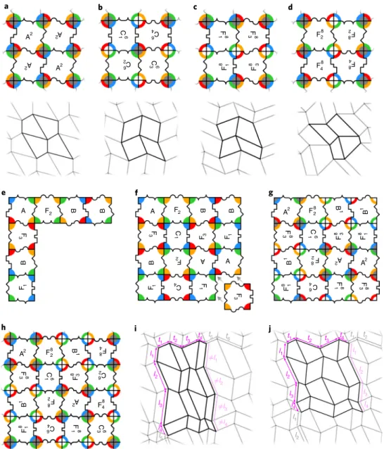
Fig. 1 | rigidly foldable tiles. a, A group of symmetry-related 4-vertices. The colour indicates the sector angle and the centre grey circle indicates
supplementation. Ba, anticlockwise-ordered base vertex with sector angles αj, fold angles ρj,j+1 and folding operators Pj; Bc, clockwise-ordered base vertex,
with inverse fold operators; Sa, supplemented vertex with anticlockwise-ordered sector angles α0j:¼π�αj
I and negated fold operators; Sc, supplemented-clockwise vertex, with inverse negated operators. b, A quadrilateral crease pattern (grey lines) composed of 4-vertices (intersections) where four creases meet. A Kokotsakis mesh (black lines) consists of four vertices grouped around a central quadrilateral plate (yellow). For such a mesh to fold, equations (1) and (2) must be satisfied. c, An example crease pattern for tile A1 with the choice of sector angles {α
j} = {60°, 90°, 135°, 75°}; note that a different
choice of sector angles results in this same tile so long as the arrangement of the generating vertices around the central plate is the same. This leaves any given tile with three sector angles (α1, α2, α3) and two crease lengths (l1 and t1) that can be adjusted. d, An example crease pattern for tile A2. e, An example crease pattern for tile C6
1
I . f–h, The folding branches of A
1 (f), A2 (g) and C6 1
I (h), with the folding branch (I or II) of each vertex indicated. The red (blue)
lines correspond to mountain (valley) folds (with the convention that the left-top vertex has one mountain fold). i–k, Jigsaw puzzle piece representation of A1 (i), A2 (j) and C6
1
I (k). The coloured rings correspond to the sector angles on the central plate, intruding/extruding notches encode the orientation
and 2, we physically fold all 14 branches of a 3D-printed, 3
×
3 tiling
(additional details are provided in Supplementary Information).
We note that our branch counting argument requires the base
vertex to not be collinear; in particular, counting the branches of the
Miura-ori pattern, where all vertices are collinear, is a much more
complex problem
16.
Beyond these elementary examples, we have devised a procedure
to systematically create all possible
m
×
n
tilings. This begins by
rep-resenting each tile as a combination of 1 of 34 ‘prototiles’ (A
−
K
2),
which encode the orientation and handedness of each vertex, and
1 of 8 supplementation patterns that encode the supplementation.
This representation underlies the super/subscripts of our tiles; for
example C
61
I
combines prototile C
1and supplementation pattern
6. We group prototilings into four classes (1–4), such that within
each class, three prototiles placed into an L-shape admit a unique
fourth fitting prototile. We refer to this as the triplet completion
rule, which provides the key simplification in the construction and
enumeration of prototilings. In each class, at least one prototile out
of a subset of ‘necessary’ prototiles has to be present; in addition,
some classes contain a group of ‘optional’ prototiles, which may
or may not be present. Each prototile is a necessary prototile in
precisely one class (Table
1
).
The possible number of prototilings in each class follows from
the combinatorics of planting at most one ‘seed’ row and one ‘seed’
column, since these uniquely define the bulk due to triplet
com-pletion. For class 1, the seed row and column can be chosen
inde-pendently; for class 2, only one periodic prototiling exists (up to
permutations); for classes 3 and 4, either a seed row or seed column
can be freely chosen. Working out the combinatorics, we obtain
exact expressions for the number of
m
×
n
prototilings,
Np
(Table
1
;
note class 4 counting is slightly more complicated and depends on
the even/oddness of the number of rows/columns, as we explain in
the Supplementary Information). To extend this counting to tilings,
we enumerate the number of allowed supplementation patterns,
Ns
,
t1 t2 t3 t4 t5 t6 t1 t2 t3 t4 t1 t2
l1
≠l1
l2
≠l2
l3 ≠l
3
l3 l2 l1
l2 l1
l4 ≠l4
l5
l4
l3 l2 l1
l4
A2 2 A
A
2 A2
C
6
1 6 C 4
C
6
2 C
6
3
F
8
1 3F 8
F
8 1 8 F3
F82 F
8 2
F48 8 F 4
A2 F 8
F
8
3 C
F
8 3 C
B
1 82 F 2 A
F48
F
8 1 64 C 1F 8 C A2 F8
2
B
1 84 F
F
8
3 1C6 8 F3 62 C
B
1 8 F
2 A
2 F8
4
F
8 1 64 C 1F 8 3C 6
a b c d
g f
e
A F2
B
B
F
3
B
F1
A F2 B B
F
3 1C F3 F1
B F
2 A
A
F1 4 C 1F
F
3
A2 F28
B
1 1 B
F
8
3 1C6 8F3
F
8 1
B
1 82 F 2 A
A2
F
8 1 64 C 1F 8 3F8
j
h i
Fig. 2 | Jigsaw origami tilings. a, A-tiling and the corresponding Huffman crease pattern22. b, C-tiling and the corresponding Barreto’s MARS crease
pattern9,21. c,d, Two different examples of F-tilings (each generated from different puzzle pieces) and the corresponding trapezoidal crease patterns. e, A seed column and row of prototiles. f, The remaining prototiles in the bulk can be uniquely filled in. g, Assigning one of two possible supplementation patterns. h, A periodic 4 × 4 class 1 tiling. i,j, By choosing sector angles and adjusting crease lengths (tk and lk), crease patterns generated from the tiling
Letters
NaTure PHysics
that are compatible with each prototiling. Our exact counting
argu-ment for the number of tilings is applicable when the base vertex is
not collinear, not flat-foldable, and does not have an equal pair of
opposing angles (see Supplementary Information). We find that in
all classes the number of tilings, given by the product of
Np
and
Ns
,
grows exponentially with (linear) system size (Table
1
), and in total
already exceeds 2 million for all 4
×
4 tilings.
We illustrate our design procedure for class 1 crease patterns,
which are based on A, B, C and F tiles. First, we design one seed
column and one seed row of prototiles (Fig.
2e
); second, we fill in the
bulk (Fig.
2f
); third, we assign a compatible supplementation pattern
(Fig.
2g
). The seed column and row determine whether these tilings
are periodic or aperiodic (Fig.
2g,h
). To translate tilings to crease
pat-terns, we pick one set of generating sector angles, and then the linear
dimensions of each seed row and column. Each
m
×
n
tiling
there-fore corresponds to a family of crease patterns with (
m
+
n
+
3)
inde-pendently tunable parameters. Choosing generic crease dimensions
for a periodic tiling will yield an aperiodic crease pattern (Fig.
2i
),
but optimized dimensions can yield periodic crease patterns (Fig.
2j
).
This illustrates that first designing tilings and then choosing sector
angles and linear dimensions opens up a vast design space.
To illustrate the combinatorics that underlies the design of class
1 tilings, we choose one of two possible supplementation patterns
by focusing on A
2tiles and assume without loss of generality that
these are rotated upright or upside-down. We then summarize
the potential juxtapositions of class 1 tiles in adjacency diagrams
(Fig.
3a
). These adjacencies stipulate that: A and B strips need to be
separated by an F patch of odd length; an F strip of even length
sepa-rates either two A, or two B strips. Using these rules, we can
system-atically construct 2
m+1seed rows of length
m
and 2
n+1seed columns
of length
n
, where each row and column either have one or more
necessary A or B tiles (and no C tiles), or have C tiles (but not A
or B tiles); these seed columns and rows span the full space of class
1 tilings. (Similar adjacency diagrams can be constructed for the
other classes and underlie our counting procedures; see Methods
and Supplementary Information.)
Naturally, the choice of seed rows and columns must also
deter-mine the ultimate folded shape(s). To demonstrate how, we
con-sider an 11-tile strip consisting of patches of A, B and F tiles, and
vertically extend this to an 11
×
6 tiling (Fig.
3b
). The
correspond-ing crease pattern admits two foldcorrespond-ing branches (Fig.
3c,d
). In the
first, the horizontal folds are all valleys while the vertical folds
alternate between mountains and valleys, leading to a cylindrical
folded shape (Fig.
3e
). In the second, the horizontal folds alternate,
while the vertical folds are all valleys in A patches, mountains in B
patches, and alternating mountains and valleys in F patches, leading
to a folded state that, when viewed edge-on, juxtaposes negative,
positive and zero curvature in the A, B and F patches, respectively
(Fig.
3f
). This illustrates that the sign of the curvature in the folded
shapes is encoded by the seed rows and columns.
We can harness this link between tile choice and curvature to
design a single crease pattern that folds into two target shapes. To
demonstrate this for two shapes involving markedly distinct
cur-vatures, we choose the Greek letters
α
and
ω
. Working once more
with class 1 tiles, we embed the curvatures for these symbols along
the leftmost seed column and upper seed row of a 36
×
36 tiling
(Fig.
3g,h
). By adjusting the crease lengths to modify the magnitude
of the local curvature and avoid intersections in the flat crease
pat-tern, we constructed a crease pattern whose two folded states closely
approximate our desired shapes (Fig.
3i,j
; to see this simulated
pat-tern rigidly folding between the two shapes, see Supplementary
Video 3, and for more details see Methods). We note that here we use
a base vertex that is flat-foldable, as we observed that crease patterns
based on generic vertices form 3D folded shapes that can exhibit
‘torsion’ when viewed edge-on. To realize a physical manifestation,
we laser-score two 50 cm
×
60 cm
×
0.20 mm Mylar sheets with this
same pattern and manually fold them, pinching each crease
accord-ing to the correspondaccord-ing MV designation. The folded specimens
closely match the simulated shapes, fleshing out the notion of
tiling-based design of pluripotent origami (Fig.
3k,l
).
Exploiting symmetries to ensure foldability, our approach can
be easily implemented by scientists, engineers and designers alike,
with potential applications in mechanical metamaterials, robotics
and deployable structures. Particularly for the case of
metamateri-als, our work opens the door to creating systems that are far more
complex than standard patterns such as the Miura-ori, involving,
for example, multi-vertex unit cells or globally disordered patterns.
Our method encompasses restricted tiling problems for (existing)
crease patterns with additional relations between the sector angles
of the base vertex, such as flat foldability
3,18,29. While we have
pre-sented an intuitive design approach, it is possible a more rigorous
computational framework could be incorporated to design complex
target shapes
30. Our results provide a starting point for constructing
and designing non-rigid and multi-stable folding structures
8,10.
Online content
Any methods, additional references, Nature Research reporting
summaries, source data, statements of code and data availability and
associated accession codes are available at
https://doi.org/10.1038/
s41567-019-0677-3
.
Table 1 | classification, counting and combinatorics
class Necessary prototiles Optional
prototiles Number of prototilings (Np)
Number of supplementation
patterns (Ns)
Number of branches (Nb)
1 {A, B} {Ck, Fk} 8(2m − 1)(2n − 1) 2 2
2 {Ck} – 8 2m+1 + 2n+1 − 2 2m+1 + 2n+1 − 2
3a {E
k, Fk, Gk, Hk, Ik, Kk} {Ck, Dk, Jk} 8(8n − 3n) 2n+1 2n+1
4-1 (m even)a {D
k, Jk} {Ck} 8(3n + 1 − 2n+1) 2n+1 2n+1
4-1 (m odd)a {D
k, Jk} {Ck} 8(3n + 1 − 2n+1) 2n+1 2n+1
4-2 (m even)a {D
k, Jk} {Ck} 16(2n − 1) 2nþ1�2þ2
mþ2 2
I 2
n+1 4-3 (m odd)a {D
k, Jk} {Ck} 8(2n − 1) 2nþ1�2þ2
mþ3 2
I 2
n+1 4-4 (m odd)a {D
k, Jk} {Ck} 8(2n − 1) 2nþ1�2þ2
mþ1 2
I 2
n+1
Necessary and optional prototiles for each class, as well as the number of m × n prototilings (Np) number of associated supplementation patterns (Ns) and number of branches (Nb). aTilings in classes 3 and
4 are either row-specified or column-specified. Expressions are for row-specified tilings; expressions for column-specified tilings follow by m ↔ n. The subclasses of class 4 depend on the occurrence of J
Received: 21 March 2019; Accepted: 30 August 2019;
Published: xx xx xxxx
references
1. Felton, S., Tolley, M., Demaine, E., Rus, D. & Wood, R. A method for building self-folding machines. Science 345, 644–646 (2014). 2. Miskin, M. Z. et al. Graphene-based bimorphs for micron-sized,
autonomous origami machines. Proc. Natl Acad. Sci. USA 115, 466–470 (2018).
3. Miura, K. Method of Packaging and Deployment of Large Membranes Report No. 618 (Institute of Space and Astronautical Science, 1985).
4. Kuribayashi, K. et al. Self-deployable origami stent grafts as a biomedical application of Ni-rich TiNi shape memory alloy foil. Mat. Sci. Eng. A 419, 131–137 (2006).
5. Wilson, L., Pellegrino, S., & Danner, R. Origami inspired concepts for space telescopes. In 54th AIAA/ASME/ASCE/AHS/ASC Structures, Structural Dynamics, and Materials Conference (2013).
6. Evgueni, T. P., Tachi, T. & Paulino, G. H. Origami tubes assembled into stiff, yet reconfigurable structures and metamaterials. Proc. Natl Acad. Sci. USA
112, 12321–12326 (2015).
7. Schenk, M. & Guest, S. D. Geometry of Miura-folded metamaterials. Proc. Natl Acad. Sci. USA 110, 3276–3281 (2013).
8. Silverberg, J. L., Evans, A. A., McLeod, L. & Hayward, R. C. Using origami design principles to fold reprogrammable mechanical metamaterials. Science 345, 647–650 (2014).
9. Waitukaitis, S., Menaut, R., Chen, B. G. & van Hecke, M. Origami multistability: from single vertices to metasheets. Phys. Rev. Lett. 114, 055503 (2015).
10. Silverberg, J. L. et al. Origami structures with a critical transition to bistability arising from hidden degrees of freedom. Nat. Mater. 14, 389–393 (2015).
11. Chen, B. G. et al. Topological mechanics of origami and kirigami. Phys. Rev. Lett. 116, 113501 (2016).
12. Dudte, L. H., Vouga, E., Tachi, T. & Mahadevan, L. Programming curvature using origami tessellations. Nat. Mater. 15, 583–588 (2016).
13. Overvelde, J. T. B., Weaver, J. C., Hoberman, C. & Bertoldi, K. Rational design of reconfigurable prismatic architected materials. Nature 541, 347–352 (2017).
14. Bertoldi, K., Vitelli, V., Christensen, J. & van Hecke, M. Flexible mechanical metamaterials. Nat. Rev. Mat. 2, 17066 (2017).
15. Lang, R. J. Origami Design Secrets: Mathematical Methods for an Ancient Art 2nd edn (Taylor and Francis, 2011).
16. Ginepro, J. & Hull, T. C. Counting Miura-ori foldings. J. Int. Seq. 17, 14108 (2014).
Horizontal adjacencies a
g h
j
i k
f d c
e b
l Vertical adjacencies
C
6 3 C6
2
C62
C64
C
6
1
C
6
1
C
6
3
C64
A2
A2 A
2
A
2
F
8
1
F
8
1 B1
B
1 1B
F
8
3
F
8 3
F
8 1
F28
F84 F
82
F
8 4
F
8 1
F
8 3
F
8
3
F48
F8 2 F
82
F
84
A2
A2
A2
A2 A2
A2
A2 A2 A
2 2 A
A
2
A
2
A
2
A
2
A
2
A
2
F8
2 F82
F84
F8 4
F8 4
F84 F
84
F
8 4
F
8 2
F
8 2 F8
2 F
8 2
B
1
B
1 B1
B
1
B
1
B
1
B
1
B
1
B
1 1 B
B
1
B
1
B
1
B
1
B
1
B
1
B
1
Fig. 3 | rational design of pluripotent crease patterns. a, Adjacencies in class 1 patterns. The purple lines connect pairs of tiles that can be joined along
the indicated edge; the grey dashed lines indicate a periodic boundaries. b, A 1 × 11 row combining A, B and F strips forms a tiling when extended with alternating periodic rows. c,d, Crease patterns corresponding to the tiling in b for branch I (c) and branch II (d) using a base vertex of αj = 60°, 75°, 120°,
105°; mountains (valleys) are coloured red (blue). (Note that the special choice of a flat-foldable base vertex does not affect the branching or folding behaviour relevant to the construction of the tilings/crease patterns shown in this figure—see Supplementary Information for a detailed discussion of this point.) e,f, Folded states according to the branches shown in b,c. g–j, Independent design of a row and column leads to a 36 × 36 tiling (g) and corresponding 37 × 37 vertex crease pattern (h) that is programmed to fold into either the letter α (i) or the letter ω (j). The purple/beige colouring indicates A and B tiles, which are important for the curvature. k,l, A Mylar sheet, laser scored with the crease pattern shown in h and folded into a 3D letter α (k) or letter ω (l). The 5 euro cent coin (diameter 21.3 mm) indicates the scale. The rigid-folding simulations and images for panels e, f, i and
Letters
NaTure PHysics
17. Arkin, E. M. et al. When can you fold a map? Comp. Geom. 29, 23–46 (2004).18. Waitukaitis, S. & van Hecke, M. Origami building blocks: generic and special four-vertices. Phys. Rev. E 93, 023003 (2016).
19. Chen, B. G. & Santangelo, C. D. Branches of triangulated origami near the unfolded state. Phys. Rev. X 8, 011034 (2018).
20. Evans, A. A., Silverberg, J. L. & Santangelo, C. D. Lattice mechanics of origami tessellations. Phys. Rev. E 92, 013205 (2015).
21. Barreto, P. T. Lines meeting on a surface: the ‘Mars’ paperfolding. In Proc. 2nd International Meeting of Origami Science and Scientific Origami (ed. Miura, K.) 323–331 (Tokyo Seian University of Art and Design, 1997). 22. Huffman, D. A. Curvature and creases: a primer on paper.
IEEE Trans. Comp. C 25, 1010–1019 (1976).
23. Tachi, T. Generalization of rigid foldable quadrilateral mesh origami. J. Int. Assoc. Shell Spat. Struct. 50, 173–179 (2009).
24. Kokotsakis, A. Uber bewegliche Polyeder. Math. Ann. 107, 627–647 (1933). 25. Stern, M., Pinson, M. B. & Murugan, A. The complexity of folding
self-folding origami. Phys. Rev. X 7, 041070 (2017).
26. belcastro, S.-M. & Hull, T. C. Modeling the folding of paper into three dimensions using affine transformations. Lin. Alg. Appl. 348, 273–282 (2002). 27. Izmestiev, I. Classification of flexible kokotsakis polyhedra with quadrangular
base. Int. Math. Res. Not. 3, 715–808 (2017).
28. Stachel, H. Flexible polyhedral surfaces with two flat poses. Symmetry 7, 774–787 (2015).
29. Demaine, E. & Orourke, J. Geometric Folding Algorithms: Linkages, Origami, Polyhedra (Cambridge Univ. Press, 2007).
30. He, Z. & Guest, S. D. Approximating a target surface with 1-DOF rigid origami. In Origami 7: Seventh International Meeting of Origami Science, Mathematics, and Education (ed. Lang, R.) 505–520 (Tarquin Publications, 2018).
acknowledgements
We thank B.G.-g. Chen, C. Coulais, Y. Shokef and P.-R. ten Wolde for fruitful discussions, D. Ursem and R. Struik for technical support, and the Netherlands Organization for Scientific Research for funding through grants NWO 680-47-609, NWO-680-47-453 and FOM-12CMA02.
author contributions
M.v.H. conceived of the project. P.D. carried out the experiments. P.D., N.V., S.W. and M.v.H. developed the theoretical framework. P.D., S.W. and M.v.H., wrote the manuscript.
competing interests
The authors declare no competing interests.
additional information
Supplementary information is available for this paper at https://doi.org/10.1038/
s41567-019-0677-3.
Correspondence and requests for materials should be addressed to S.W.
Peer review information Nature Physics thanks Zeyuan He and the other, anonymous,
reviewer(s) for their contribution to the peer review of this work.
Reprints and permissions information is available at www.nature.com/reprints.
Publisher’s note Springer Nature remains neutral with regard to jurisdictional claims in
published maps and institutional affiliations.
Methods
4-Vertices. A 4-vertex consists of four rigid plates connected by four flexible hinges
that meet in a central point. In all cases, we consider sector angles that add to 2π, with each angle <π. In origami, one often encounters non-generic vertices, where the sector angles are related in some manner18. In our work, we need to consider
three types of such non-generic vertex: collinear vertices, for which αj+αj+1=π
for at least two values of j, flat-foldable vertices for which αj+αj+2=π for all j, and
vertices that have an opposing pair of sector angles that are equal (αj=αj+2 for a
least one value of j). We note in passing that the Miura-ori fold is both collinear and flat-foldable, and thus highly non-generic.
All of our results are immediately applicable to generic vertices, which we define as not collinear, not flat-foldable, and without pairs of equal opposing sector angles. However, many of our results require weaker restrictions. In particular, our results for the number of folding branches require the vertices only to be not collinear; our tiling creation remains valid for non-generic tilings, but the counting of the number of tilings in a class may be affected by all non-genericities. For details, see the Supplementary Information.
The folded configurations are characterized by the folding angles ρj,j+1, defined
as the deviation from in-plane alignment between adjacent plates j and j+ 1 (modulo 4). A folded generic 4-vertex always has one fold whose folding angle is opposite in sign from the others9,18,22. We call the two folds that are capable of
having the opposite sign unique folds, and these folds straddle a common unique plate9,18. Without loss of generality, we define our sector angles such that ρ
41 and ρ12 are the unique folds, with plate 1 being the unique plate. This is equivalent to
demanding that9,18
α1þα2<α3þα4 ð3Þ
α4þα1<α2þα3 ð4Þ
Vertices can be flipped ‘upside-down’, and to break this symmetry we assume for the base vertex (without loss of generality)18:
α2>α4 ð5Þ
The two branches, together with the {ρj,j+1} ↔ {−ρj,j+1} symmetry, yield four distinct
MV patterns for vertex Ba (Supplementary Fig. 1a). We denote the folding branches where ρ41 or ρ12 has the opposite sign as branches I and II, respectively. For the
supplemented vertices Sa and Sc, for which we have α0 j¼π�αj I
, inequalities equivalent to equations (3) and (4) specify that α3 is the unique
plate (Supplementary Fig. 1b)9.
Folding operators. On a given branch, 4-vertices have one continuous degree of freedom, and it is therefore possible to determine operators (functions) that map the value of any given fold to any other. For the vertex Ba, we define the folding operators, BaPI;II
j I
, which map the fold angles adjacent to plate j in an anticlockwise manner: BaPI;II
j ðρj�1;jÞ ¼ρj;jþ1
I
(Supplementary Fig. 1c). The superscripts I and II reflect the fact that these operators are different for each branch of the vertex, but to avoid clutter we suppress these when possible. Explicit expressions for these operators can be readily derived, which shows that they are bijective and anti-symmetric: Pj(−ρ) =−Pj(ρ) (see Supplementary Information). As the
mirrored vertex Bc interchanges clockwise and anticlockwise orientations, it follows that BcPj¼BaP�1
j
I
. In addition, it can be shown that Saρ j¼ �Baρj
I
, and Scρ
j
I
=Saρ�1
j ¼ �Baρ�j1
I
(Supplementary Fig. 1c). These expressions can be derived from the explicit expressions for the folding operators, and have an elegant interpretation in terms of spherical mechanisms (see Supplementary Information).
Tiles. Constructing tiles. To obtain foldable multi-vertex structures, we imagine placing one of the vertices, Ba, Bc, Sa or Sc, in one of its four orientations, at each corner W–Z of a quadrilateral (Supplementary Fig. 1d), resulting in 65,536 candidate meshes. The candidate meshes are foldable only when they satisfy two compatibility conditions. First, the angles around the central plate must obey the ‘sum condition’:
αWþβXþγYþδZ¼2π ð6Þ
Second, the sequential execution of operators around the central plate must yield the identity operation. This leads to the nonlinear ‘loop condition’ expressed as an identity of the ‘operator quad’:
PZ
δPYγPXβPWα ¼I ð7Þ
By checking these compatibility conditions, we find that 544 of the 65,536 candidates rigidly fold. Several of these are related by tile rotations, leaving the 140 distinct tiles corresponding to Fig. 1. In Supplementary Fig. 2, we show real-space versions of these tiles for a particular choice of generating sector angles.
Representation. We represent foldable Kokotsakis meshes, regardless of their generating angles {αj}, with puzzle pieces that encode all relevant information.
White circles indicate unsupplemented vertices (Ba and Bc); grey circles indicate supplemented vertices (Sa and Sc). Notches pointing from plate j to j+ 1 distinguish between anticlockwise-ordered vertices (Ba and Sa) and clockwise vertices (Bc and Sc). The shape of the notches encodes the corresponding fold angles: cusp →ρ12, triangle →ρ23, semicircle →ρ34, square →ρ41. The coloured
rings, which correspond to the sector angles on the central plate, also encode orientation and aid visualization. The combination of white/grey circles and notches completely specifies each of the 65,536 candidate meshes. Finally, we note that tiles that have a geometric fit and matching grey/white colouring consistently define their shared vertices, which turns crease pattern design into solving a tiling problem.
Prototiles. Here we explain the rationale behind the prototile representation. First, the only combinations of generic sector angles {αj} that add up to 2π (that is, satisfy
the sum rule) are permutations of {α1, α2, α3, α4}, fα01;α02;α03;α04g
I and f
αj;α0j;αk;α0kg
I
, where j=k is allowed. In all such combinations, the number of supplementations per tile is even. However, an even number of supplementations does not change the operator quad, as (−1)2= 1 and all operators are anti-symmetric. Therefore,
one can determine all compatible tiles by first establishing all ‘primitive’ operator quads that combine ρ and ρ−1 to satisfy the loop condition, and then applying
appropriate pairs of permitted supplementations. The prototile representation therefore delineates between vertex type and orientation with supplementation (Supplementary Fig. 3). We find that there are 34 of these prototile combinations of primitive operators P and P−1 that (up to cyclic permutations) satisfy the loop rule.
These can be further organized into 11 groups (responsible for the A–K lettering and subscripts) as determined by the form of the operator quads (Supplementary Table 1 and Supplementary Fig. 3a).
Each prototile allows two, four or six supplementation patterns, labelled 1–8 (and responsible for superscripts in our notation—see Supplementary Fig. 3b). The number of prototiles per group, np, the number of supplementation patterns
per prototile, ns, the number of tiles per group, nt, and the number of operator
quads per group, nq, as well as the allowed supplementation patterns within
each group are summarized in Table 1.
Folding branches. Each tile can be folded along multiple branches. Explicitly denoting the branch for the folding operators, we can determine the number of branches for a given tile by counting the number of combinations of I and II labels in the operator quads that lead to identities. All tiles allow for at least two folding branches, where all vertices are on either branch I or branch II, but some tiles further allow for four or six branches. We explicitly present the possible branches for all tiles in the Supplementary Information.
Further considering the patterns that emerge in counting tile branches, we see that the numbers two, four or six arise because we can organize all operator quads into three groups. First, for tiles {A, B}, all operators need to be on the same folding branch, yielding two different folding branches. Second, the operator quad of the Ck prototiles, PIk;II ðPIk;IIÞ�1PIk;II ðPIk;IIÞ�1
I
, yields identity when adjacent pairs of operators are on the same branch (for example, {I,I,II,II}, {II,I,I,II}, {I,I,I,I} and so on, yielding six branches). Third, all other tiles contain pairs of distinct operators, and as both pairs need to be on the same branch, this yields four folding branches (Supplementary Fig. 3).
Solving of combinatorial problems. Using the classification, supplementation
patterns and folding branches of individual (proto)tiles, we have determined the number of m×n prototilings and, for each, the number of supplementation patterns and folding branches, by solving a slew of combinatorial tiling problems. A full explanation of our approach can be found in the Supplementary Information, but here we lay out the main steps of our arguments.
Tiling classes. We have found that it is possible to group prototiles into four classes based on considering whether an L-shaped triplet of prototiles admits a fourth compatible prototile (Supplementary Fig. 4a). The fourth prototile consists of four vertices, three of which are directly specified by the prototile triplet, and the fourth of which follows (up to supplementation) from the sum rule and observation that each compatible tile has an even number of clockwise-ordered vertices. If the fourth prototile does not occur within the set of 34 compatible prototiles, the triplet of prototiles are not in the same class (Supplementary Fig. 4b). If the fourth prototile is 1 of the 34 compatible prototiles, all four prototiles are in the same class (Supplementary Fig. 4c).
We note that as the number of supplementations per tile is even, the supplementation patterns also satisfy triplet completion and, consequently, tiles can be grouped into four classes and also satisfy triplet completion. Finally, we note that we put C tiles in a separate class 2, even though these are optional tiles in all other classes. Similarly, D and J tiles (class 4) appear as optional tiles in class 3. The reason for this is that we recognize that the counting of the number of supplementation patterns or branches is easier within the four classes we define.
Counting prototilings. To calculate the number of m×n prototilings, Np, in each
Letters
NaTure PHysics
In all classes, we find that the numbers of potential fits at the north/southside and the east/west side of each prototile are equal, which means that these connection numbers are preserved in rows and columns. The combination of triplet completion and the conservation of connection numbers greatly simplifies the explicit construction of all m×n prototilings: triplet completion implies that we, at most, need to construct one seed row and one seed column to uniquely determine each prototiling, and the conservation of connection number facilitates the construction of these rows and columns. The only remaining problem is the placement of necessary and optional prototiles, but this turns out to be solvable (in different ways) for each class, once one realizes that the orientation of prototiles (that is, 90° rotations) needs to be considered. Summing over all allowed placements and orientations and then constructing the number of corresponding edge columns and rows allows us to obtain exact expressions for Np in each class.
In the Supplementary Information, we derive all expressions in full detail.
Counting supplementation patterns. To calculate Ns, the number of supplementation
patterns for m×n prototilings in each class, we focus on vertices rather than tiles. This transforms the counting of supplementation patterns to a relatively simple two-colouring problem, where we designate each vertex as supplemented or not, subject to the constraints set by the allowed supplementation patterns of each prototile (Supplementary Fig. 3). We find that class 1 tilings admit two supplementation patterns, irrespective of size, while for tilings in the other classes the number of supplementation patterns grows exponentially with system size.
Counting tilings. The results for the number of prototilings, Np, and the number of
allowed supplementation patterns, Ns, can be multiplied to obtain the number of
possible m×n tilings in each class. As shown in Table 1, this leads to complicated yet tractable expressions. An important by-product of solving the technical details of the counting is obtaining practical procedures to explicitly construct tilings in each class. We demonstrate this below in the context of class 1 patterns.
Counting the number of branches. To calculate Nb, the number of folding branches
for m×n tilings in each class, we first note that while the MV pattern depends on the supplementation, the assignment of branches I or II to each vertex is independent from the supplementation. In fact, vertices can be ‘coloured’ as branch I or II in an analogous way to supplementation. Hence, counting branches is again a two-colouring problem, where we now assign each vertex in a prototiling to be on branch I or II, subjected to constraints set by the allowed branch patterns of each prototile (Supplementary Fig. 3). We find that class 1 tilings admit two branches, irrespective of size, while for tilings in the other classes, the number of branches grows exponentially with system size (for exact expressions, see Table 1; for exact counting, see the Supplementary Information).
Design of class 1 crease patterns. In the main text, we consider a tiling
specified by a row consisting of 3 × 1 A, B and F patches, and columns consisting of only A, B or F tiles (Fig. 3). Here we consider a more complex tiling, where the top row and left column consist of 3 × 1, respectively 1 × 3, strip of A, B and F tiles, leading to a tiling consisting of 3 × 3 patches of A, B, F and C tiles (Supplementary Fig. 5). The tiles in the interior follow from the tiles in the top row and left column; for example, C tiles are located wherever we find F tiles on the top row and left column.
The two folding branches of class 1 patterns follow from fixing all vertices on branch I or branch II (see Supplementary Information). To determine the corresponding MV patterns, we first summarize the MV patterns for each tile,
and from this determine the MV patterns for each of the respective A, B, F and C patches (Supplementary Fig. 6a–c). Combining these, we can construct the two distinct MV patterns of the complex tiling (Supplementary Fig. 6d,e). For folding branch I, the horizontal folds have a single value along a connected line of folds: valleys for patches 1–3, alternating valleys and mountains for patches 4–6 and mountains for patches 7–9 (Supplementary Fig. 6d,e). The vertical folds alternate and do not lead to any overall curvature. Hence, once folded, the top and bottom patches exhibit opposite curvatures, while the middle patch forms a corrugated sheet that is flat at large scales—the precise curvature pattern is thus set by the left column. For folding branch II, the curvature pattern is set by the top row: the vertical folds are valleys in patches 1, 4 and 7, alternating valleys and mountains for patches 2, 5 and 8, and mountains for patches 3, 5 and 9. This illustrates that the patterns of A, F and B tiles in the top row and left column can be used to arbitrarily control two independent curvature patterns for the two folding branches of the corresponding crease patterns.
Rational design. While the sign of the curvature is directly controlled by the tilings, the magnitude can be controlled by the ‘concentration’ of A and B tiles in a background of F tiles, and by the linear spacing associated with each tile. This allows the straightforward design of crease patterns that fold into complex, targeted curvature patterns. Using these principles, the design of tilings and corresponding crease patterns that fold into two independently defined shapes is straightforward (see Fig. 3).
Owing to our conventions for defining the ordering and orientation of the base vertex Ba, the qualitative behaviours described in the previous paragraph are independent of any generic choice of generating angles. Nonetheless, there are some practical considerations in choosing these. We use two sets of sector angles {αj} in our crease patterns. Most cases correspond to {αj} = {60°, 90°, 135°, 75°},
which is a generic vertex (not flat-foldable) following the conventions equations (3)–(5). For the design of the β-crease pattern and the α−ω crease pattern, we choose {αj} = {60°, 105°, 120°, 75°}, which is flat-foldable29 (α1+α3=α2+α4). While
our designs also work for generic vertices, self-intersecting (‘bowtie’) quadrilaterals are harder to avoid there. The linear crease dimensions are chosen such that vertices are reasonably spaced, without self-intersections of creases—for finite patterns, this is always possible. Finally, we note that an m×n tiling determines an m+ 1 ×n+ 1 vertex pattern. Edges to these patterns are in principle arbitrary; we defined the truncated vertex shapes at the edge by extending the tilings with additional rows and columns.
Sample fabrication. To create the folded specimen in Fig. 3, we laser score two 50 cm by 60 cm Mylar sheets with a thickness of 0.2 mm. We program the laser cutter to burn the crease pattern 0.1 mm deep into the sheet, where all cuts are on one side, to make the sheet more easily bent along the locations of the folds. We then draw the crease patterns onto both sheets with a permanent marker. After manipulating all folds, we can then fold the two sheets into their final shapes, shown in Fig. 3i,j. The scored lines on the sheet correspond exactly to the crease pattern in Fig. 3f except with one edge of plates corresponding to the edge of the ‘ω’ side deleted, resulting in a 37 × 38-plate pattern. This is carried out in consideration of the fact that edges of the pattern can be extended or retracted with no effect on the foldability and minimal effect on the shape.